

Page 1

Installation & Parts Manual
LectroCount® Remote Display
Installation: EM100-13
Page 2

Table of Contents
Description Page Number
Model Numbers.................................................. 2
Specifications ..................................................... 3
Installation .......................................................... 4-6
Installation Requirements...................... 4
Remote Display Label ........................... 4
Mounting Dimensions ........................... 5
Optimum Viewing Angle ........................ 6
Remote Display Shield Accessory ........ 7
Bolt & Torque Specifications ................. 7
Decimal Point Jumper Setting ............... 8
Publication Updates and Translations
The most current English versions of all Liquid Controls publications are available on our website, www.lcmeter.com.
It is the responsibility of the Local Distributor to provide the most current version of LC Manuals, Instructions, and
Specification Sheets in the required language of the country, or the language of the end user to which the products are
shipping . If there are questions about the language of any LC Manuals, Instructions, or Specification Sheets, please
contact your Local Distributor.
Wiring Diagrams ................................................ 9-10
LectroCount LCR-II ............................... 9
Select Switch Kit....................... 9
LectroCount LCR .................................. 10
LectroCount3......................................... 10
Dual Display Kit ..................................... 11
Illustrated Parts Breakdown ............................... 12
!!
WARNING WARNING
!
WARNING
!!
WARNING WARNING
• Before using this product, read and understand the instructions.
• Save these instructions for future reference.
• All work must be performed by qualified personnel trained in the proper application, installation, and
maintenance of equipment and/or systems in accordance with all applicable codes and ordinances.
• Failure to follow the instructions set forth in this publication could result in property damage, personal injury,
or death from fire and/or explosion, or other hazards that may be associated with this type of equipment.
Model Numbers
Two LectroCount® Remote Display Models are available
for interface to Liquid Controls LectroCount Electronic
Registers. Ensure that the model number of the
LectroCount Remote Display is compatible with the
LectroCount Electronic Register prior to installation. If
the device does not match the model number, the system
will not work and may be damaged when power is applied.
An identification label appears on the top of the remote
display (Figure 1). This label designates the device for
which the remote display is designed. It will not work
with other devices. The label also contains the Serial
Number of the unit. This information will be useful when
contacting Liquid Controls for assistance.
Figure 1. Remote Display Identification Label
E1610 - For use with: LectroCount® LCR-II
E1611 - For use with: LectroCount® LCR®, LectroCount
®
3
2
Page 3

Specifications
The LectroCount Remote Display is a 6-digit, backlit display with 2¼" high digits, viewable to 100 ft, for flow metering
applications.
LectroCount Remote Display models are available for LectroCount LCR®, LectroCount LCR-II® and LectroCount³
Electronic Registers.
Model E1610 - For use with LectroCount LCR-II
Model E1611 - For use with LectroCount LCR and LectroCount³
Features include:
• 6-digit, backlit display with 2¼" high display characters.
• 30 ft, 4-wire, shielded cable.
• Class I, Division 2 Group C & D weatherproof NEMA 4X enclosure.
• Weights & Measures Approvals in USA and Canada when used with LectroCount Electronic Registers.
• Viewable up to 100 ft.
Wiring: Connections from the LectroCount register to the LectroCount Remote Display should be made using 22
gage, 4-wire, shielded cable or larger. Thirty feet of cable is provided with the display. The maximum length of cable
allowable is 100 ft. The 4-wire cable includes conductors for power, ground, and two signals.
Figure 2. LectroCount Remote Display
SPECIFICATIONS
Environmental
Design for: Class I, Div. 2, Group C & D
NEMA 4X
Operating Temp. Range*: -22º to 158º F
-30º to 70º C
Approvals
US Weights & Measures: NTEP COC 86-022
Canada Weights & Measures: AV-2342
Electrical
Power: +5 to 15 VDC, 500 mA, Maximum
*At lower temperatures, the liquid crystal display may have a delayed
response rate.
Signal Input
Input Signal Levels: Hi
Maximum Frequency Input:
Signal Source: Frequency
LectroCount LCR 5 kHz
LectroCount LCR-II N/A
LectroCount LC
3
≥≥
≥ 2.50 VDC
≥≥
≤≤
Lo
≤ 2.0 VDC
≤≤
3
5 kHz
Page 4

Installation
!!
! CAUTION
!!
The LectroCount Remote Display and accessories (whether supplied by Liquid Controls or other) must be installed
and operated in accordance with all applicable federal, state, and local construction, electrical, environmental
and safety codes. Failure to do so could result in serious injury or death.
This unit is designed for Class I, Division 2, Group C & D areas.
Do not install in Class I, Division 1 areas.
Installation Requirements
• Read this manual prior to start of installation. If you
have any questions, consult with your full service
distributor or call the Service Department at Liquid
Controls.
• This display should always be securely mounted to
a platform or supportive member. Ensure that the
display does not experience excessive vibration or
shock.
• The LectroCount Remote Display is designed to be
compatible with a specific LectroCount Electronic
Register as specified by the customer and as
indicated on the Serial Number Tag. No attempt
should be made to use the display with an input
different from the one originally specified.
• The LectroCount Remote Display is supplied with a
30 foot cable, which should be adequate for most
installations. If additional cable is required, cable
kits are available from Liquid Controls. It is
recommended that a 4-wire, shielded cable with 22
gage wire or larger be used. The maximum length
of cable allowable is 100 feet.
The LectroCount Remote Display is supplied ready for
final cable termination. Should it be necessary to replace
the cable between the signal source and the remote
display, be sure to secure the cable and tighten the cover
so as to maintain the vapor seal.
Remote Display Label
The LectroCount Remote Display is shipped with the units
of measure displayed on the label in Gallons. The
application in which the display is being utilized may
require a different unit of measure.
Figure 3. Remote Display Label
The LectroCount Remote display is shipped with four (4)
additional unit of measure labels. To change the unit of
measure, remove the desired label from it’s backing and
place over the “Gallons” label on the display. The area
around Gallons is recessed and the sticker can easily
be positioned for placement.
4
Page 5
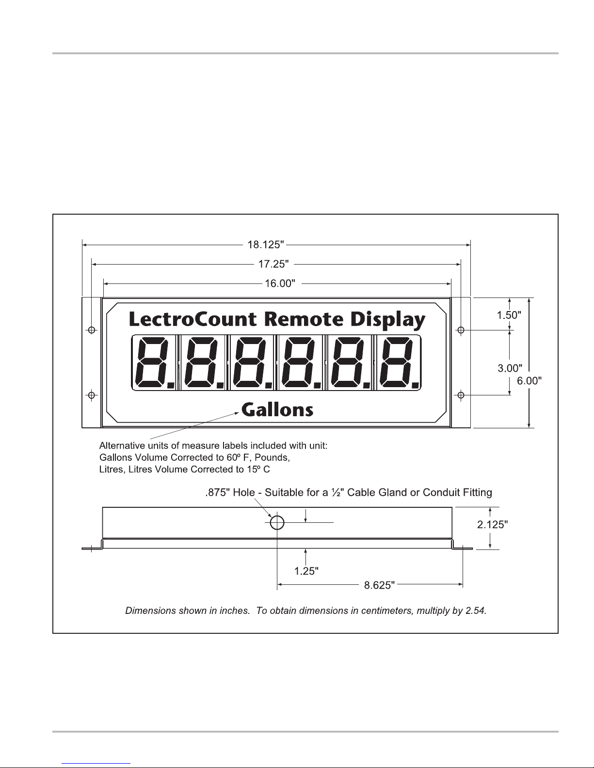
Mounting Dimensions
The LectroCount Remote Display should be mounted
using the four holes provided in the rear cover. The hole
size is designed for use with ¼" screws. It is important
to select a mounting location which will position the
display as close to the optimal viewing angle as possible
(see Page 6).
Installation
The diagram below shows the overall dimensions and
the locations of the mounting holes on the LectroCount
Remote Display.
Figure 4. Remote Display Dimensions
NOTE: Dimensions shown are not for construction use.
Consult factory when certified Engineering Drawings are required.
5
Page 6

Installation
Optimum Viewing Angle
LCD displays have an optimum viewing angle. Displays
lose contrast and become more difficult to read at some
viewing angles and are easier to read at other angles.
Because the viewing angle is limited, a bias is designed
into the module at the time it is manufactured. The result
is a nominal viewing angle which is offset from the
perpendicular by a specified amount. The Liquid Controls
LectroCount Remote Display is designed with a bias set
to accommodate as wide a viewing area as possible.
Optimum viewing with the greatest contrast will occur
when the display is viewed between 20º above and 40º
below horizontal. If the display is viewed outside this
range, the display contrast will reduce to a point where it
reaches an unacceptable viewing level. The horizontal,
side to side viewing angle is 40º left and right from center.
Figure 5. Optimum Viewing Angle
6
Page 7
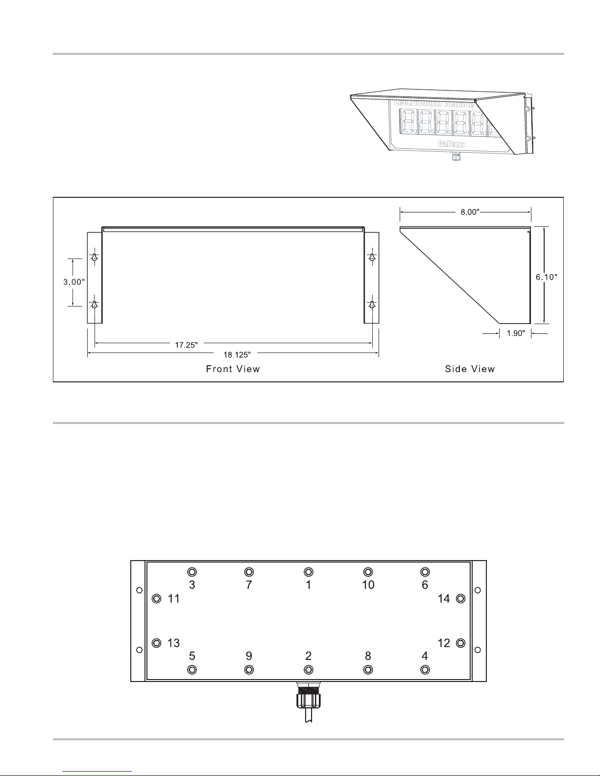
Remote Display Shield Accessory (PN 81879)
There are certain applications where sun or bright light
may produce glare on the display. Use the optional shield
to reduce the effect of glare. This shield fits in place over
the LectroCount Remote Display as shown in Figure 6.
The holes in the shield are slotted for ease of installation.
Figure 6. Remote Display Shield
Installation
Figure 7. Remote Display Shield Dimensions
NOTE: Dimensions shown in Inches (to obtain centimeters, multiply values shown by 2.54).
Bolt & Torque Specifications
It may be necessary to open the Remote Display for the
purpose of changing the decimal point jumper setting
(Page 8), or to connect wires to J1 or J2. There are 14
bolts on the rear panel of the Remote Display which need
to be removed to gain access to the printed circuit board
(PCB). When work on the internal components is
complete, the bolts need to be tightened to the proper
torque specification and in the proper sequence to ensure
that the unit is resealed properly to prevent moisture from
entering.
Insert each bolt and tighten by hand, then tighten the
bolts according to the sequence show below. The bolts
should be tightened to 5-8 In. LBS. (80-128 In. Oz.)
Figure 8. Remote Display Torque Pattern.
7
Page 8

Installation
Decimal Point Jumper Setting
NOTE: Model E1610 automatically displays the identical
decimal configuration appearing on the LectroCount
LCR-II display. There is no need to adjust the jumpers
on Model E1610.
Once the enclosure is opened, the jumpers may be moved
to configure the display according to the LectroCount
Electronic Register for which it is designed. See the table
below for jumper settings.
The LectroCount Remote Display may be configured to
show the decimal point in one of three positions:
• Whole Units (No Decimal Point)
• Tenth Units
• Hundredth Units
This is accomplished by moving the J3 and J4 jumpers
on the Remote Display PCB. The PCB is accessed by
removing the 14 screws on the back of the enclosure.
The jumpers are located on the bottom left side of the
PCB, to the left of the J2 connector (Figure 9).
NOTE: The jumpers need to be in position. Do not remove
and discard them. If Whole Units is desired, then J3 and
J4 must BOTH have jumpers in the OFF position.
NOTE: If J3 and J4 are BOTH in the ON position, then 2
decimal points will appear on the display. This is not a
valid jumper configuration.
J3 J4 J2
Figure 9. Jumper Locations
DEVICE MODEL No.
LectroCount LCR-II
LectroCount LCR,
LectroCount³
Table 1. Decimal Point Jumper Setting.
E1610
E1611
Whole Units Tenth Units
J3 J4 J3 J4 J3 J4
OFF OFF OFF OFF OFF OFF
OFF OFF ON OFF OFF ON
Hundreth Units
8
Page 9

Model No. E1610
For use with LectroCount LCR-II
Once the display is mounted, the factory installed
cable should be routed to the LectroCount LCRII. Choose an unused port on the LCR-II and
connect the cord grip provided. Route the cable
through the cord grip and connect the cable to
the J12 Connector on the LCR-II PCB as shown
in Figure 10.
J12 J1
Pin 39 Pin 21 (WHITE)
Pin 40 Pin 22 (GREEN)
Pin 41 Pin 23 (BLACK)
Pin 45* Pin 20 (RED)
Wiring Diagrams
*If the power supplied to the LCR-II ever exceeds
+24VDC, then the remote display should be powered
from Pin 32 on J8, +5VDC.
Figure 10. LCR-II Wiring Diagram
LectroCount LCR-II - Select Switch Kit Accessory (PN 82593)
This kit is not required for operation of the LectroCount
Remote Display with the LectroCount LCR-II. It is an
optional accessory which allows the user to select the
various displays available from a remote location. The
switch kit accessory does not connect to the LectroCount
Remote Display, it is wired directly into the LectroCount
LCR-II.
The Select Switch Kit includes the following:
• Push Button (& cord grip)
• Cord Grip (2)
• 4-port Conduit Box
• 30 Foot, 2-wire, Shielded Cable
The 4-port Conduit Box can be configured as desired.
Each port is the same size (½") so the plugs and cord grip
and switch may be reconfigured to suit the application.
When a location has been determined for the switch kit,
mount the conduit box. Route the 30 foot cable provided
to the LectroCount LCR-II and connect the cord grip to an
available port on the back of the LCR-II. Route the free
end of the 30 foot cable through the cord grip on the back
of the LCR-II. Connect the two wires for the Select switch
to terminal J8 on the LCR-II PCB as shown in Figure 11.
RED to Pin 35
BLACK to Pin 38.
Figure 11. Select Switch Wiring Diagram
When a delivery is active, pressing the Select Switch will
cause the display to show the current flow rate. After 5
seconds, the display returns to current flow total.
9
Page 10

Wiring Diagrams
Model No. E1611
For use with LectroCount LCR
Once the display is mounted, the cable should
be routed to the LCR. Choose an unused port
on the LCR and connect the cord grip provided.
Route the cable through the cord grip and
connect the cable to the J12 Connector on the
LCR PCB as shown in Figure 12.
J12 J1
Pin 39 Pin 21 (WHITE)
Pin 40 Pin 22 (GREEN)
Pin 41 Pin 23 (BLACK)
Pin 45* Pin 20 (RED)
When functional, the remote display will match the LCR
display. No external reset switch is required for operation.
*If the power supplied to the LCR ever exceeds +24VDC,
then the remote display should be powered from Pin 32
on J8, +5VDC.
Model No. E1611
For use with LectroCount³
Once the display is mounted, the cable should
be routed to the LectroCount³. Choose an
unused port on the LC³ and connect the cord
grip provided. Route the cable through the cord
grip and connect the cable to the J1 Connector
on the LectroCount³ PCB as shown in Figure 13.
J1 (LC³) J1 (Remote Display)
Pin 1 Pin 20 (RED)
Pin 2 Pin 23 (BLACK)
Pin 5 Pin 21 (WHITE)
Pin 6 Pin 22 (GREEN)
Figure 12. LCR Wiring Diagram
When functional, the remote display will match the LC³
display. No external reset switch is required for operation.
Figure 13. LC³ Wiring Diagram
10
Page 11

Dual Display Kit (PN 82594)
(For use with Models E1610 & E1611)
The Dual Display Kit is designed for use with two (2)
LectroCount Remote Displays and a single LectroCount
Electronic Register. This kit contains:
• 4-Port Junction Box
• Cord Grip (2)
• Nipple & Seal Washer
Dual Display Kit
5. Route the cable from the unopened Remote Display
through a cord grip attached to the junction box.
6. Route the removed cable through a second cord grip
in the junction box.
7. Connect both cables to J1 on the PCB.
The LectroCount Remote Displays are equipped with a
30 ft, 4-wire, shielded cable.
To install the Dual Display Kit:
1. Open one of the units by removing the 14 bolts on
the back panel.
2. Disconnect the cable from J1.
3. Remove the cord grip and cable from the unit.
4. Install the 4-Port Junction Box in the space where
the cord grip was just removed.
J1
Pin 20 - Red Wire
Pin 21 - White Wire
Pin 22 - Green Wire
Pin 23 - Black Wire
8. Replace the cover on the back of the display following
the specifications on Page 7.
9. Connect the loose end of the cable to the LectroCount
Electronic Register as shown on Pages 9-10.
Figure 14. Dual Display Kit - 2 Remote Displays with 1 LectroCount Electronic Register
11
Page 12
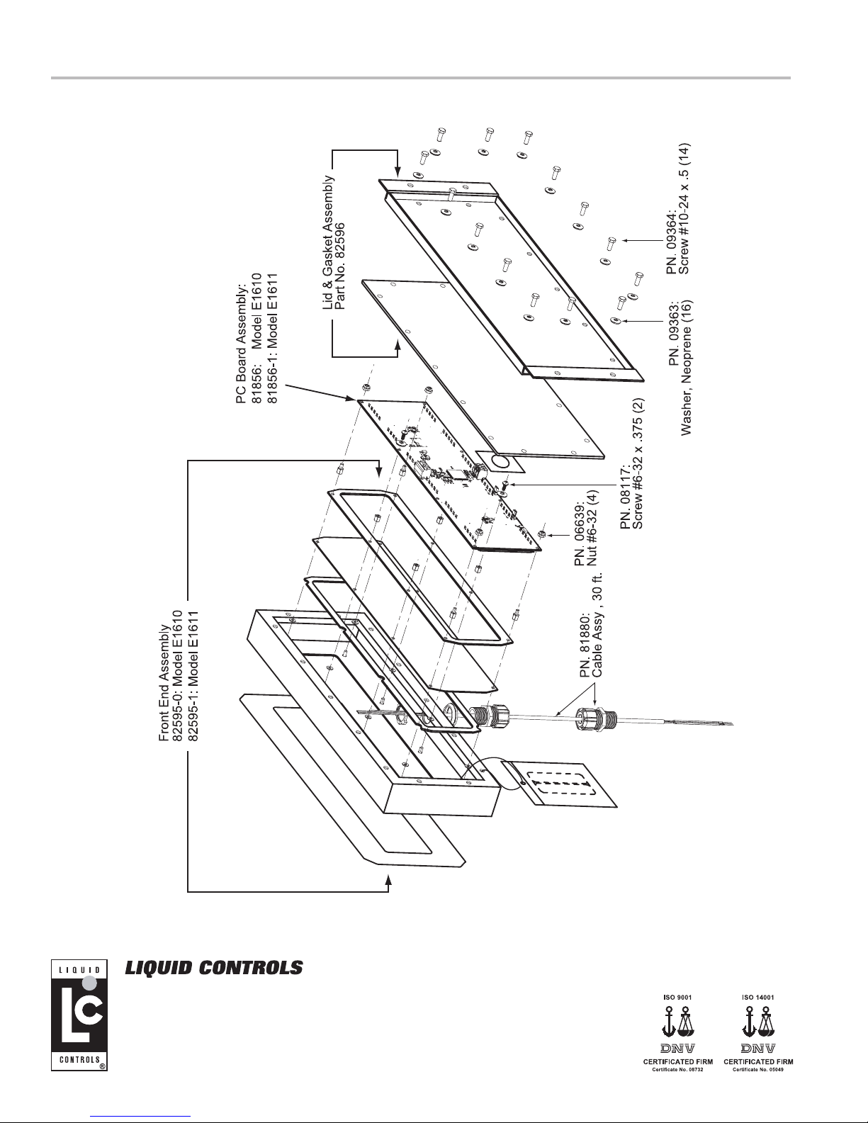
Illustrated Parts Breakdown
A Unit of IDEX Corporation
105 Albrecht Drive
Lake Bluff, IL 60044-2242
1.800.458.5262 • 847.295.1050
Fax: 847.295.1057
www.lcmeter.com
© 2007 Liquid Controls
Pub. No. 500316
(07/20/07)
 Loading...