

Page 1
LIPPERTCOMPONENTS, INC.
COACH STEP
AUTOMA TIC ELECTRIC STEPS AND AUTOMATIC ELECTRIC SLIDING STEPS
Keep clear of steps as they are deployed. Step actuation takes approximately two seconds whether extending or retracting.
Keep hands and fingers away from step mechanism during actuation process to prevent serious bodily injury.
TEST PROCEDURE PRIOR TO INST ALLATION
1. Steps will install easier when extended first. Place steps upside down on workbench or floor.
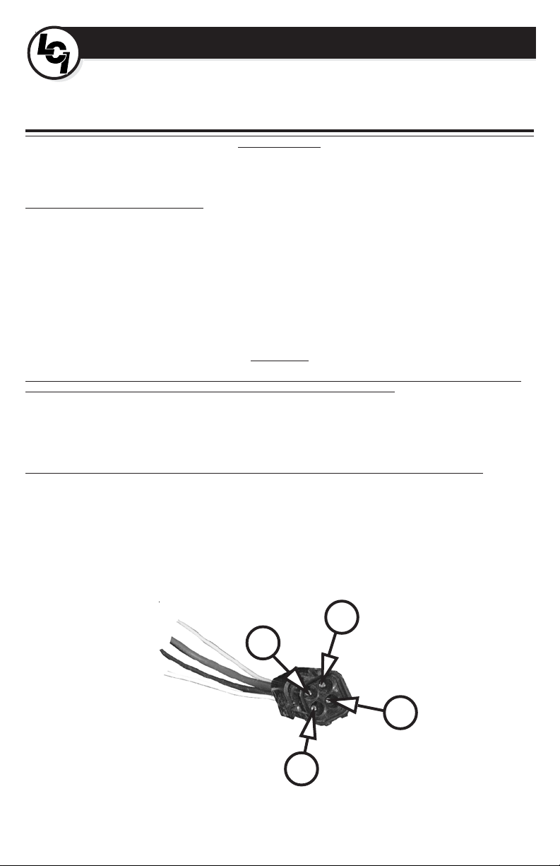
2. Cut and connect four (4) jumper wires to the 4-pin connector. Match the jumper wires to the posts on the connector color for color.
3. Connect GREEN WIRE to the NEGATIVE post of a fully charged, 12V automotive battery .
4. Connect RED and WHITE WIRES to the POSITIVE post of the battery.
5. Connect the BROWN WIRE to the NEGATIVE post of the battery .
6. Disconnect jumper wires from the battery.
Steps must be installed using four (4) 5/16”, GR 8 bolts, lock washer and nuts for the Automatic Elctric Steps and 3/8” bolts, lock washers and
nuts for the Automatic Electric Slideing Step. Retract steps by attaching wires in the following sequence:
1. Ground the GREEN WIRE to the chassis.
2. T ouch the RED and WHITE wires to the positive terminal on the battery .
Proceed to install door switch and power switch(items not included). The wires of the four pin connector must be routed as follows:
1. WHITE - Connect to power switch (16 ga. min. wire).
2. YELLOW - Must be connected to power source that is only hot when ignition is “ON.” Protect with 6A fuse or breaker (16 ga. min. wire).
3. RED - Connec to power for motor. Protect with 25A fuse (10 ga. min. wire).
4. BROWN - Connect to door switch (16 ga. min. wire).
INSTALLATION, OPERATION AND SERVICE MANUAL
RECREATIONAL VEHICLES
FOR
INSTALLA TION PREP
WARNING!
WARNING!
Steps will extend immediately!
INSTALLA TION
Keep clear of the steps as they will retract quickly.
WARNING!
Fig. 1
2
3
4
1
Page 2
INSTALLA TION - DOOR SWITCH
Lippert Components, Inc. (LCI) recommends the use of the LCI supplied switch. However, if another switch is to be used, it must be a switch held
open in the presence of a magnet and should have a triggering distance of no more than one inch.
Steps are designed to extend when the door switch closes (magnet is removed) and the switch completes the ground.
The Door Switch is ideally installed 6 inches above the floor on the hinge side of the door frame. The magnet will be installed on the door
immediately opposite. The distance between the magnet and the switch should be determined by trial unit the steps begin to extend when the door
is open around 6 inches.
Wires are best installed out of sight and away from sharp objects and potential snags. It is very important that a good ground is supplied in an
area not likely to corrode, as this can contribute to step failure.
NOTE: Installation of the Door Switch is a critical element in the installation of the step. The switch must be installed so that any flexing of the
door frame does not cause the step to extend. Conversely, the switch must trip early enough so when the door is opened, the steps extend prior to
the passenger exiting the coach. The steps should begin extending prior to the door opening 6 inches.
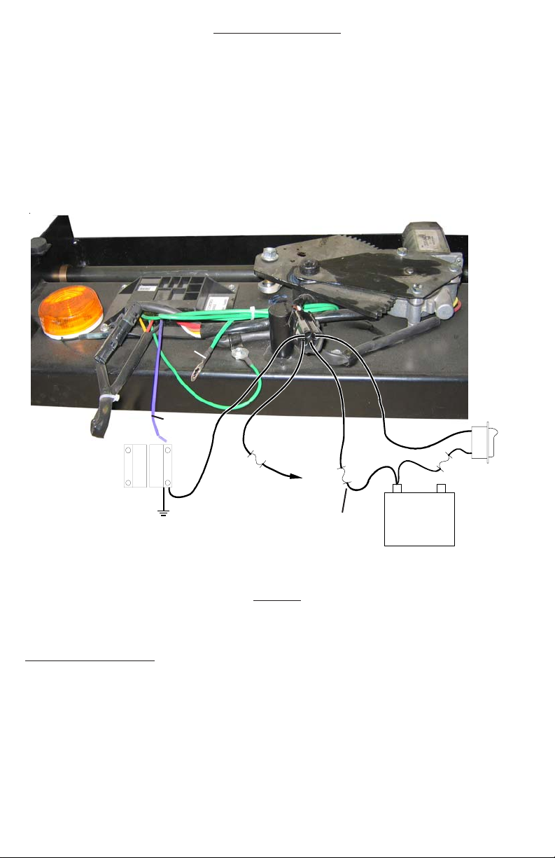
GREENGROUND TO
CHASSIS
WHITE
STEP LIGHT
Fig. 2
SWITCH
6A FUSE
BROWN
DOOR SWITCH
TO FUSE
PANEL
YELLOW
CIRCUIT
PROTECTOR
RED
+ -
6A FUSE
POWER
SWITCH
BATTERY
OPERATION
Look downwards toward the steps prior to exiting the coach. It is possible to lock the steps in the retracted position.
STEP OPERATION - POWER “ON”
1. Turn Power Switch to “ON” position.
Prior to exiting the coach, passengers must be sure steps are fully deployed.
WARNING!
2. Open door.
3. Steps will extend and lock when in the fully extended position.
4. Amber entry lamp will illuminate automatically .
5. Close door.
6. Entry light will shut off and steps will retract.
Page 3

With Power Switch “ON,” door open and steps extended, it is possible to drive off. Damage to steps or vehicle is possible, as well
as serious personal bodily injury or death.
STEP OPERATION - POWER “OFF”
1. With door open, steps extended and Power Switch turned “OFF ,” steps remain extended; amber light shuts off.
2. If the steps are to be retracted with the door open, turn the power switch ON, retract the steps and turn power switch OFF . The steps will
remain retracted.
3. With door closed, steps extended and Power Switch “OFF,” turning the ignition “ON” will automatically retract step s.
4. When door is opened and ignition turned off, steps will extend one last time - last man out feature.
5. If door is opened and closed without full extension of the steps, the steps will retract and stay until Power Switch is turned “ON” and door
reopened.
NOTE: If step’s full extension is impeded by an external object like a curb, steps will cease operation and shut down. Steps will retract normally .
Steps must always be operated with a fully charged battery. Because the step s can detect obstacles in the way of operation by
sensing excessive amperage, a fully charged battery is imperative. Any drop in voltage will cause the steps to malfunction.
With Power Switch “ON,” door open and steps extended, it is possible to drive off. Damage to steps or vehicle is possible, as well
as serious personal bodily injury or death.
Due to the fact that the step detects obstacles by sensing excessive current draw, it is imperative that the step be tested with a fully
charged battery and test wires be at least 12 GA. Do not attempt to test the steps using a battery charger or bench type power
supply. Even though they may supply a full 12VDC, a momentary drop in the supply may fool the module into thinking that the
steps have encountered an obstacle.If using a battery to test the steps, care should be taken to connect jumpers to the battery
first and then to the steps. Battery acid can cause injury and automotive type batteries under load can produce hydrogen gas.
They may explode if shorted out or if a spark ignites the hydrogen gas when the battery is connected to a load.
No repairs should be attempted by anyone other than a qualified professional as the deployment or retraction of the steps can
cause injury if proper precautions are not taken.
WARNING!
TROUBLESHOOTING
WARNING!
WARNING!
WARNING!
WARNING!
TROUBLESHOOTING THE SYSTEM
1. Disconnect the plug between the chassis and the steps. Using a voltmeter, measure the voltage on the large red wire at the chassis
connector with the step switch in the “ON” position. The meter should indicate more than 12VDC. Turn the step switch to the “OFF” position
and the meter should not indicate voltage. If the meter indicated no voltage with the switch “ON”, check the circuit and the circuit protectors.
If it indicates less than 12VDC with the switch “ON”, charge the battery. If 12VDC are indicated on the red wire with the switch “OFF”, replace
the switch.
2. With the voltmeter, set to measure resistance, measure the resistance between the green wire in the plug and the frame of the vehicle. If there
is more than one ohm of resistance, clean the ground eye (ground lug) or relocate the ground wire.
3. Using a voltmeter, set to resistance, test for ground on the brown wire going to the door switch. The meter should indicate an open circuit
with the door closed and a path to the ground with the door open. Insure that the door is open at least 6 inches before it completes the circuit
to ground.
4. With a voltmeter, check for 12VDC on the yellow wire with the ignition switch in the “ON” position and no voltage with the switch in the “OFF”
position. If there is no voltage with the switch in the “ON” position, trace the circuit and repair.
5. Reconnect the steps to the chassis and proceed to test as follows. With step switch “ON” and the ignition key “OFF” open the entry door and
the steps should extend and the light should come on.
6. If the light comes on, but the steps do not deploy, remove the step assembly from the motor home.
7. Remove the two bolts that hold the step arm collars to the drive shaft. This will allow you to operate the steps manually. If the step s do not
operate freely, visually inspect for bent arms or tight joints. The shoulder bolts should rot ate in the bushings with very little effort. Repair or
replace as needed.
8. If the step moves freely, unplug the module from the motor assembly at the two pin connector . Connect 12VDC from the battery to the yellow
wire going to the motor and ground the red wire. The gear should rotate in the deployment direction until it goes over center and comes to
rest against the stop. (If the steps were deployed, reverse the wires to drive the gear in the opposite direction). If the gear and motor
assembly will not function normally replace them, otherwise replace the module assembly.
Page 4

SERVICE NOTES
A. Use locktite on any bolts removed and replaced.
NOTE: It is recommended that if the nut is removed and replaced in the field, a liquid “Loctite” locking compound be applied before tightening.
The joint shoulder bolts should be torqued to a minimum of 140 inch pounds.
B. How to adjust cams.
It is not recommended that the tightness of the step be adjusted in the field. Some minor movement of the step is considered normal.
Excessive movement could be an indication of a more serious prob-lem and the bottom cover should be removed and a thorough visual inspection
should be made before any attempt is made to repair the problem by adjusting the cams. The cams are located on the inside of each side plate.
Should it be deemed desirable to adjust the cams, they can be adjusted by loosening the nut on the outside of the side plate, and rotating the cam
and bolt so that they bear more heavily against the step arm. Care should be taken so that both cams are adjusted approximately the same
amount. After adjust-ment, the steps should be operated several times to insure that they are still locking over center. This can be determined by
watching the steps as they complete their deployment. If the steps are locking over center, they will deploy fully and then retract approximately 1/8”
as they lock in place.
C. Installation Precautions
The steps are designed to be mounted to the vehicle by at least 4 bolts. It is recommended that at least 10mm bolts and flange nuts be
used. In no case should the step be welded to the vehicle. This could result in warpage, unreliable performance, and electrical damage to the
module.
D. Service motor as an assembly.
It is strongly recommended that the motor/gear be serviced as an assembly and this is the way replacements are sold. The motor/
gear assembly can be replaced by disconnecting the two pin connector from the module to the motor, removing the “p” clamp holding the wire
harness to the motor mount, removing the ball joint linkage from the gear, the self-tapping screw that holds the ground wire and by removing the 3
bolts that hold the motor mount to the step base. Care should be taken not to disturb the adjust-ment in the length of the ball joint linkage. After
reassembly in the reverse order, no adjustment should be required.
E. Module replacement.
Remove the self-tapping screw holding the ground wire, and disconnect the 4-pin connector to the motor home wiring and the two-pin
connector to the motor. Remove the self tapping screws holding the module in place, and reinstall the new module in the reverse order.
F. Lubrication Coach
Steps are equipped with self-lubricating bushings on the drive assembly and all step joints. No lubrication is necessary . If in extreme
conditions lubrication is deemed necessary a silicon based grease or spray will not harm the bushing material.If any difficulty is encountered
either in the use, installation or service of the steps that is not covered in the service instructions, please call the following number for service or
warranty information. The manufacturer takes no responsibility for unauthorized service or installation procedures.1-866-524-7821.
 Loading...