

Page 1
LIPPERTCOMPONENTS, INC.
CENTER POINT SUSPENSION INSTALLATION GUIDE
Installation for the Trailair Center Point suspension system is straight forward and requires replacing the equalizer in the standard tandem(2)
axle suspension system. Trailair strongly recommends the use of shock absorbers in conjuction with Center Point but they are notrequired.
Trailair does not supply shock absorbers because Center Point is not designed structurally to handle shock absorber mountings.If the coach is
not equipped with shock absorbers, please refer to the trailer manufacturer for information on shock absorbers and/or themountings available for
the particular trailer.
1. The first step is to check for fit up and take reference
measurements. Please see the EQUALIZER / HANGER FITUP
ILLUSTRATION which depicts a standard center hanger ,
equalizer (also referred too as a “rocker”) with spring shackles
and the Trailair Center Point Installation Check Template.
Utilize the illustration and a Check T emplate (CP 100001) to
determine if adequate clearance is available under the coach
and which length shackles are required during installation.
Make sure you catalog the “S” dimension measurement for
reference in section 9.
2. For a standard
installation, your coach must
also come equipped with the
standard center hanger shape.
The hanger may vary in
dimension but it must be sized
for a 1 3/4” leaf spring width, be
at least 2.5” from the equalizer
hole to the top of the hanger and be 3” wide or wider. Please
refer to the EQUALIZER / HANGER FIT-UP ILLUSTRA TION
for minimum hanger dimensions. If your coach is not equipped
with this style hanger, you may be able to do a non-standard
installation (See section 8) or you may have to remove the
old hanger from the frame and install the standard center
hanger, which can be acquired from Trailair.
3. After safely
raising the coach to
a level that insures
the tires are off the
ground, properly
position stands to
support the coach.
WARNING: improper raising or lowering of the coach could
result in damage to the coach, injury or death. Insure that
any points of contact for the stands do not result in damage
to any panels or lines under the coach.
4. Remove the tires and
wheels from the coach. The
suspension should be free from
any loads, except it’s own weight
at this point. Place another set of
jack stands under the axles, very
close to the u-bolt plates. This will
provide support to the axles and
insure that they do not swing down during disassembly of the
shackle components. NOTE: allowing the axles to drop could
result in damage to the wiring for the electric brakes.
5. With the coach properly raised on jack stands and
the axles properly supported by additional jackstands, remove
two shackle nuts on the shackle at the rear of the front spring.
NOTE that the bolts are pressed into the shackle plate and
should not turn. However, use a properly sized boxed end
wrench to insure the bolts do not turn. Loosen the nuts only,
to remove these shackle
plates.
6. Once the nuts and
the plate retained by the
nuts are removed, slide the
opposite side shackle plate
out, with the bolts still
pressed into the plate. Also, remove the nut on the cross bolt
for the equalizer. Again, the bolt may be pressed into the
frame hanger and should not be allowed to rotate. After
removing the front spring’s shackle at the equalizer, repeat
the process for the shackle that mates the rear spring to the
equalizer. Then, remove the equalizer.
7. The frame hanger is now ready to receive a Center
Point Sub-assembly. Insure that the clamp plates are
sufficiently loose to allow the retaining tower to slide up into
the frame hanger. Do not remove the clamping plates as
there may not be adequate clearance to reinstall after placing
the tower into the frame hanger. Remove the retaining cross
bolt and nut so the tower will slide into the frame hanger. Do
not misplace these
bolts and nuts after
taking them off the
sub-assembly. If
the hanger has a
cross tube, the
cross tube must be
removed.
STANDARD SUB-ASSEMBL Y
8. It is suggested that a floor jack supports the Center
Point Sub-assembly during this operation. The floor jack
allows mobility along with an ease of slowly raising the Center
point Sub-assembly into position to install the retaining cross
bolt into the frame hanger.
DO NOT REMOVE SIDE CLAMP PLATES
Page 2
NON-STANDARD SUB-ASSEMBL Y
In specific cases where the side clamping plates
cannot be used
with a nonstandard
size
centerhanger,
an alternative
mounting is
possible. If the
CP2 sub-unit
will fit inside the
hanger, and the
hanger is tall enough, the sub-unit may be mounted without
the side clamping plates if (2) crossbolts are used instead of
(1) (An additionial pair of 9/16” x 12 x 3” grade 8 bolts with
nylock nuts will be needed as only one per sub-unit are
provided). The CP2 sub-unit is designed with two crossholes
in the tower to give Center Point an additional inch in height
adjustment. Both holes can be used for mounting cross
bolts(although not needed in a standard installation).The
additional hole in the centerhanger of the coach frame will
need to be drilled and will correspond with the secondary
adjustment hole. A secondary installation is shown with a
hanger that was only 2.5” wide.
If either the side clamping plates or the (2) crossbolt
method cannot be used because of the size and/or shape of
the centerhanger, it is recommended that the frame hanger
first be changed to the standard size hanger.
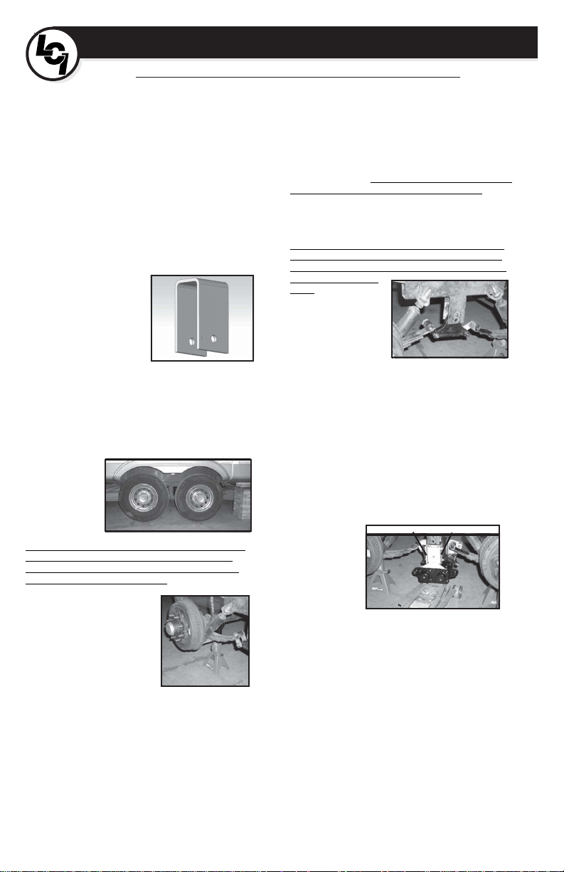
Once the Center Point Sub-assembly is properly
positioned and the mounting holes are aligned, install the
retaining cross bolt (provided on the tower of each sub-unit).
This bolt will have to be inserted from the outside, inward.
The air spring on the Center Point Sub-assembly prevents
this bolt from being inserted from the under side of the coach.
Y ou may now tighten both the retaining plate bolts and the
cross bolt. T orque these bolts to 100 foot/pounds.
9. T h e
Center Point
S u b assemblies
are preadjusted at
the factory to
insure the
cross shaft
shackle link is parallel to the ground. There are a wide variety
of equalizers being used throughout the industry. Due to the
fact there are so many, it is normally necessary to replace the
original shackles with longer ones. Trailair provides 2 sets of
shackle plates (8 plates each) that offer three different length
settings as well as (8) replacement shackle bolts and (8)
flanged nuts. The check template will give a dimension from
the center of the link eye on the Center Point assembly to the
center of the spring eye on the springs of the coach. Refer to
the EQUALIZER / HANGER FIT-UP ILLUSTRA TION
attachment in step one for the “S” dimension measurement
taken at the beginning of the procedure.
INSERT THE BOLT FROM THIS SIDE
While the slack adjusters allow for adjustment in the
relationship of the spring position to the frame, it is not intended
to offer a latitude great enough to compensate for the necessity
of replacing shackle mounting plates with those that are longer.
This is due to the design of the Center Point system and the
distances from the riser tower cross bolt to the cross shaft’s
shackle link mounting position, while in ideal conditions.
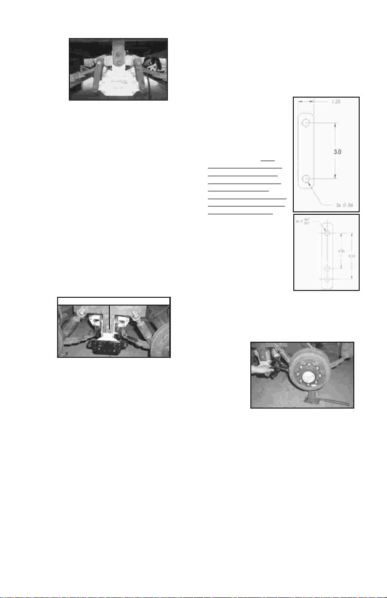
It is important to use the correct replacement shackle
plates so that the height of the coach does not change more
than 1/2”. The “S” dimension
tells us which shackle to use.
If the “S” dimension is 3” or
less, use the CP 100056
shackle plates. If the “S”
dimension is between 3” and
4” use the CP 100046 shackle
plate (which has two settings)
in the short hole set. In the
short setting, be sure that the
end of the shackle plate with
the extra hole is pointed down
to the ground and not up
toward the frame so that it does
not cause interference with the
operation of Center Point. If the
“S” dimension is more than 4”
use the longer setting of holes
in the CP 100046 shackle
plates.
Upon choosing the
correct shackle plates, the
shackles can be assembled
into the spring eyes and into the
cross shaft shackle links. Y ou
must drive the knurled shank
end of the shackle bolt onto the
shackel plate. Use of a standard bottle jack will be of
assistance in positioning the axle to align the two bolts of the
shackle plate. If a bottle jack is utilized, be sure to position it
under the spring mounting plate, below the axle. When the
two bolts on the
shackle plate
will slide easily
into both, the
cross shaft
shackle link
and the spring
eye, place the
other shackle
plate on the
inside and install the nuts to retain the shackle assembly .
Repeat this process on the other spring.
After securing all shackle nuts and bolts to proper
torque levels (50 ft/pounds), the opposite side of the coach
is ready for the same procedures. Repeat the operations 3
through 9 as described above to install the opposite side.
CP 100046
CP 100056
Page 3
PLUMBING
10. Once both Center Point Sub-assemblies are installed
onto the frame, the air supply lines must be routed. Y ou should
CP 100035
sufficient slack in the air hose, the clip placement (CP 100035)
is critical. The air spring will cycle forward and aft as much as
5 inches, during the operation of the suspension in its reaction
to extreme road conditions. Therefore, the clip must be
secured on the frame with enough slack to allow the movement
necessary. It must also be located so that the hose does not
CP U00020
location, the bulkhead fittings w/ ¼” NPT to push on (CP
U00003) can then be attached to the air hoses. The locking
nut of the bulkhead fitting can be removed from the fitting and
the fitting can be inserted into the mounting clip. Re-install
the locking nut and secure the bulkhead fitting to the clip.
the air gauge panel(CP 5007), the poly air lines may be
installed. A union tee (CP U0000
4) is supplied for joining the
two air lines from the bulkhead fittings. Note that all a ir lines
are DOT approved air brake quality suitable for commercial
industry applications. The poly air lines must be cut square
U00006), self-drilling / self-tapping screws (CP U00020) and
(4) wire ties (CP U00028) provided. Do not drill through any
panels under the coach until assuring there is nothing that
will be damaged. Remember, there are holding tanks, water
location of the air gauge panel (CP
5007) is up to the owner / dealer /
refer to the AIR LINE SCHEMA TIC in the
appendix. Before planning the air hose
routing and placement, verify there is
sufficient clearances for the air spring. The
air springs already have the air hoses
installed and only have to have the loose
end secured. In order to insure there is
contact the air spring to any other moving
parts of the suspension. There are 4 self drilling, self-tapping screws (CP 100020)
provided to attach the clip, two per clip.
11. After attaching the clips in a suitable
This should be done for both sides
of the trailer before installing the
poly air lines.
12. After carefully considering
CP U00003
and true, in order for these fittings to
function properly and retain air
pressure.
13. T o assist in routing the poly
CP U00004
air lines, there are (4) nylon clips (CP
lines and possibly gas lines all mounted
within the frame rails of a coach.
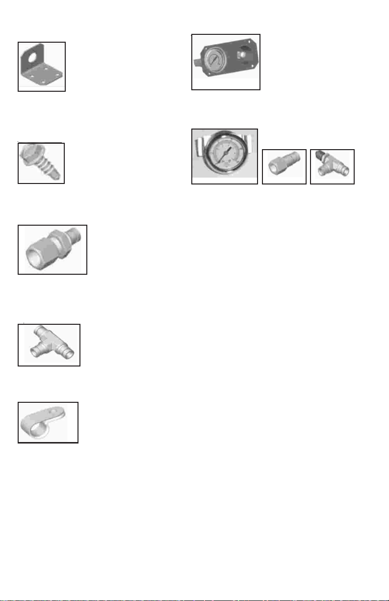
PANEL APPLICATION:
14. The choice of the
CP U00006
the placement and routing of the
air lines to the desired location of
installer. Trailair makes no recommendations other than to
consists of the panel mount plate (CP 100030), the air
pressure gauge (CP U00033) with female connector (CP
U00017) and the access fill valve (CP U00015).
CP U00033 CP U00017 CP U00015
gauge and fill valve acts as a reinforcing plate. The second
option is to mount the air pressure gauge and the access fill
valve directly onto the coach body without utilizing the panel.
Trailair offers both methods and provides sufficient information
for either choice.
PANEL MOUNTING:
The CP 5007 assembly is intended to serve two
functions. One is to provide support for the panel installation
in areas that may not be thick enough to attach fasteners.
The second function is to provide a template to cut an accessmounting
hole. Carefully check to insure there are no
obstacles nor any components that may incur damage while
cutting holes, routing the poly air lines or mounting the panel
mount plate. At this point, mount the female connector to the
air gauge, mount the air gauge and the access fill valve to the
panel mount plate.
Determine the location of the CP 5007 assembly and
mark two holes, 1 3/4” diameter, 3 3/8” apart from each other.
With a suitable tool cut the opening for the air gauge and the
fill valve. Place the CP 5007 assembly into the openings,
level and square the assembly, mark the four hole locations
to mount the panel. Install the assembly using (4) self-tapping
screws (CP U00020), through the holes in the panel.
DIRECT AIR GAUGE MOUNTING:
Once location is determined, use the air gauge
without the bezel and the access air fill valve without the
bulkhead nut as a template to drill the holes needed. Be sure
to check for potential interference and or possible damage to
other components before cutting any access holes. Once
the holes are cut, mount the air gauge with the female
connector attached and the access fill valve to the coach
sidewall.
place it where it will not inhibit
the operation of the system and
will provide an opportunity to
visually check the system
pressure easily. External
mounting is the preferred
method of Trailair, however, the
owner may prefer mounting
CP 5007
within a compartment. CP5007
There are two options for external
installation. The first option is to
install the panel mount plate
provided with the
Page 4

3 - N/A
Page 5

NO LONGER APPLICABLE
Page 6
Direct mounting of air pressure
gauge and access fill valve are
shown.
15. After installing the
be routed. Make sure the air lines can not rub on the wall of
the coach and create a leak. Install the instructional decal
provided.
ADJUSTMENT INSTRUCTIONS
The principle of the Center Point design is to allow
totally independent axle reaction to road conditions and to
also allow adjustability in equalizing coach height, in side-toside
relationship. The sub-units are assembled at the factory
at with the shackle links pre-set. The ride height of the coach
should be acheived with the selection of the shackle, not
adjusting the
shafts. However,
in some cases the
link eyes need to
be adjusted for
c l e a r a n c e
purposes.
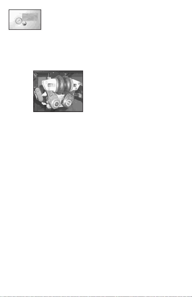
To adjust
the link eye on the
cross shafts, use
a 9/16” wrench to
turn the worm
gear in the slack adjuster. If lowering the coach, it may not be
necessary to have the weight off the the axles. However, if
raising the coach height the weight of the coach will have to
be lifted off the axles to turn the worm gear in the slack adjuster.
ADJUSTMENT POINT
Angles of 30 degrees or less from a horizontal position
are acceptable, in compensating for differences in height. Both
arms on a sub-unit should be equal when adjusting coach
height. Do not exceed 30 degrees of adjustment. Angles
greater than 30 degrees require using different shackle plate
lengths. Do not use a shackle longer than the CP 100056
shackle provided by Trailair.
SETTING AIR PRESSURE
Air pressure levels should be 5 PSI per 1,000 pounds
of coach weight at 70 degrees ambient temperature. This
will vary according to individual personal belongings and
effects that the owner wishes to place in the coach. Once a
satisfactory air pressure (yielding a compliant ride for the
coach) is established, the air pressure gauge will allow quick
and easy verification of operating pressure levels. Always
make sure the fill valve cap is secure so that the seal in the
cap will function properly and assist in sealing the system.
Keep in mind that three natural factors will effect the
air pressure in a self contained air system. The following
conditions will cause the air pressure reading in the gauge to
components, the poly air lines can
fluctuate more than 2-3 psi up or down from the conditions
the coach is set at upon installation; A change in altitude of
3000 to 4000 feet or more, a change in temperature of 50
degrees or more and 500 pounds or more of weight differential.
What does that mean? If one or more of these conditions
change for a prolonged period after the initial installation, an
adjustment to the air pressure may be required. If these are
temporary fluctuations, changes in the air pressure are most
likely not needed.
Note that once the coach is moved, the air spring
may return to a position other than centered. This is not
abnormal. It only illustrates the fact that the axles are reacting
to torque of acceleration, deceleration or turning input. The
only way to return to an absolute centered position of the air
spring is to lift the coach and allow the axles to seek a neutral
condition, having no residual torque input.
HELPFUL HINTS
If the system is leaking, add air to 100psi and begin
trouble shooting at the fitting connections with soapy water. If
the leak cannot be traced to a fitting connection, the air gauge
and the fill valve are the most likely pnuematic parts to leak.
The most unlikely component to leak is the air bags themselves
and Trailair recommends checking those last upon a fresh
installation. If the leak cannot be found and fixed, call Trailair
for assistance. Once the leak is found, reset the air pressure to
the setting for your coach.
There is no lubrication required for CenterPoint as it is
designed to perform best dry. The only maintenance would be
for the brass in the link-eyes of the shafts and standard
maintenance required for the spring eyes of the standard
suspension.
For clarity purposes, Center Point is shown in the
manual without the mechanical bag stops that are standard on
the sub-units. This allows Center Point to be operated on your
coach without air in cases where travel is necessary. So if you
have an air leak or a complete loss of air in the system, you can
still travel. It should be noted that prolonged use in this condition
can potentially accelerate the wear of the stop plates. The parts
are easily replaced if overly worn.
A full listing of all replacement parts can be found on
page 5 of the manual on the air line schematic print. Please
contact Trailair for all your replacement parts needs.
TECHNICAL SERVICE:
Direct any and all technical service questions to:
Trailair, Inc Corporate Office.
409 Vandiver West, Bldg 6-201
Columbia, MO 65202
800/998-4238 email: info@trailair.com
573/446-1086 (fax) www.trailair.com
Page 7

Page 8

The Leader in RV Air-Ride Technology
Trailair’s National sales and business office in Goshen, IN is your location to place orders, order literature,
follow up on orders and other inventory maintenance issues.
Contact information:
LIPPERTCOMPONENTS, INC.
Service & Warranty; Plant #39
2703 College Ave.
Goshen, IN 46528
Toll Free: (866) 524-7821
Phone: (574) 537-8900
Fax: (574) 534-7161
www.lci1.com
email: warranty@lci1.com
Product information and photography are as accurate as possible at the time of publication. Colors and finishes
are photographic representations and may appear different from actual materials.
rev021612
 Loading...