

Page 1
CBB07
A Division of Lippert Components
Chev / GMC
Bumper Brace
Installation Instructions
The frame brace runs between the bottom edge of the bumper and the bed
cross member near the rear tire. The connection to the bumper is made by
sandwiching the bumper between the large angular plate and the end of the
frame brace rod. The connection at the upper end of the rod is made by
connecting to an existing hole in the bed cross member.
(Drivers side installation shown)
Step 1. Assemble a right and left assembly
by placing a 3/8” x 1 ½” bolt through the
frame brace rod at the end with the ¼” thick
reinforcing block, then through the angular
support plate. Install flat washer, split lock
washer and nut, leaving a gap for the bumper .
See fig. A
The passenger side setup is the
same except the large angular
Fig. B
place protrudes from the opposite
side of the frame brace.
Step2. Slip the bumper
between the small plate on the
frame brace rod and the larger
angular large plate, with the
angular plate turned out toward
the end of the bumper.
Dashed line in Fig B. shows the
plate location above the bottom
edge of the bumper. See fig. B
Set frame
brace 1”
away from
outer bed
panel.
B
l
o
u
n
Fig. A
(Driver Side)
Bumper edge
between here.
c
k
t
u
r
n
e
d
o
u
d
e
r
b
u
t
m
p
e
r
.
w
1”
U
a
R
o
d
Plate
n
d
e
r
s
i
d
e
o
r
d
BED CROSS
MEMBER
f
b
Hex Nut &
Lock Washer
1 ½” Bolt &
Flat Washer
u
m
p
e
r
The other end of the frame brace
is attached to the bed cross
member beneath the bed of the
truck. Continue to step 3 for
installation detail for this end of
the brace.
INSTRUCTIONS CONTINUED
ON REVERSE
1030
Page 2

Step 3a. (2007-2010 only)
Secure the upper end of the
frame brace rod to the bed cross member
using the existing hole near the end
of the cross member. Secure with
3/8” x 1” bolt and hardware provided.
(except on dually trucks) See fig. C
Fig. C
Note: On Dually trucks there will be a
fender brace attached to this hole. Remove
the bolt from the fender brace, place the
bumper brace under the fender brace and
reinstall the bolt.
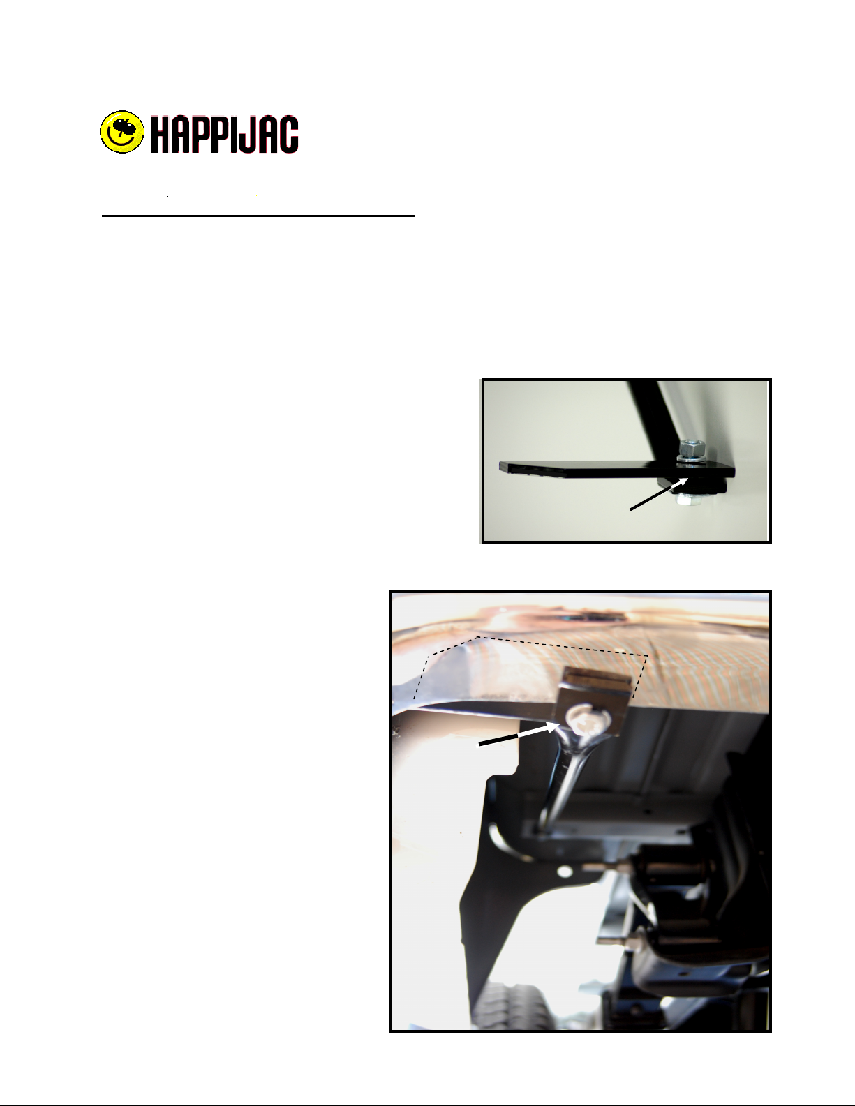
Step 3b. (2011 & Newer)
Install upper end of bumper brace at location
shown in Fig. D using the Metric M8-20
hardware supplied. (Except dually trucks)
Note: On Dually trucks there will be a
fender brace attached to this hole. Remove
the bolt from the fender brace, place the
bumper brace under the fender brace and
reinstall the bolt.
Step 4. Set lower (bumper) end of the
frame brace 1” away from body panel and
tighten both ends of frame brace.
Bed
Cross
Member
Existing
Hole
Fig. D
Install with
M8-20
Bolt, washer
& lock washer
Bed
Cross
Member
Existing
Threaded
Hole
 Loading...