

Page 1
FFRONTRONT A ANCHORNCHOR I INSTALLATIONNSTALLATION
1. Making certain of correct hole position for your
truck model, mark and drill bottom hole (to prevent drill from drifting, drill small pilot hole first
and then enlarge to 3/8”). Connect Anchor Plate
with lower bolt prior to drilling top hole.
2. Rotate Anchor Plate slightly outward so the plate
threads are not damaged while drilling top hole.
3. With tightened lower bolt to hold guide strap
firmly in place, drill top hole* (drill small pilot
hole first and enlarge to 3/8”).
4. Loosen bottom bolt to allow top bolt to start easily,
then tighten bolts.
* When stake pocket prevents top hole from being drilled at
straight angle, drill hole at the best angle permissible.
The hole angle can easily be straightened to 90º by
placing the 3/8” section of rod (included for this purpose) through the hole and tapping it with a hammer
in the direction needed to straighten the hole.
Model: CA-MT
1988 and earlier Toyota
1993 and earlier Mazda
Note: Measurements
given are from top of truck
bed to center of bottom
hole on Guide Strap
TOYOTA (Pre 1986)
TOYOTA (1986-1988)
Measure Down: 11.5”
FORD COURIER
(Pre 1977)
MAZDA (Pre 1977)
Measure Down: 10.5”
1997 and earlier Nissan
1989 and earlier Isuzu
Drawings show the front, driver’s side corner of a
pickup truck bed—looking down from above
Anchor Plate
Guide Strap
Anchor Plate
Guide Strap
Remove inner wall and follow instructions at left. Replace inner wall.
NOTES: 1. 1986 Jeep Pickup uses (4) ea. CA-UR.
2. Ford Ranger uses (4) ea. CA-UR.
3. Chevy S-10 & S-15 use CA-CG3.
FORD COURIER
(1977-1985)
MAZDA (1977-1985)
MAZDA (1986)
Measure Down: 11.5”
NISSAN/DATSUN
Measure Down: 11.5”
Anchor Plate
Guide Strap
Mount front Anchor Plate below line of
bed on front flange.
Anchor Plate
Guide Strap
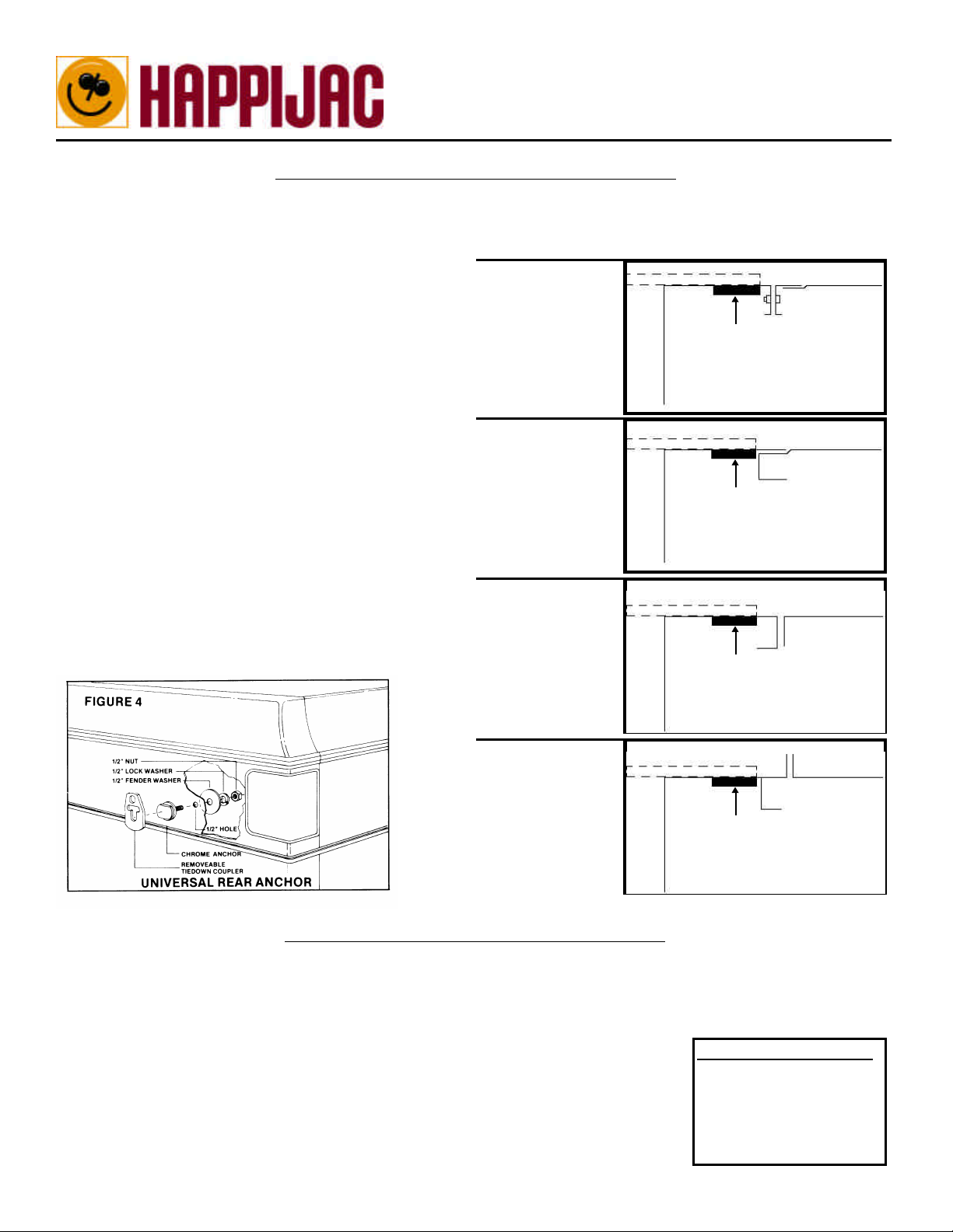
RREAREAR A ANCHORNCHOR I INSTALLATIONNSTALLATION
1. Locate universal rear anchor such that the alignment is as nearly vertical below the camper eye-bolt as possible,
and low enough to allow sufficient space between eye-bolt and rear anchor for turnbuckle installation (generally
13”-18”). WARNING: Before drilling check for clear access to the backside between outer fender and bed wall,
and check for any wires, fuel lines, etc.
2. Drill small pilot hole and enlarge to 1/2”.
3. Tightly secure chrome anchor bolt with large fender washer, lock-washer, and nut (Fig.
4)
4. Removable Tiedown Coupler connects turnbuckle to anchor.
Customer Service Numbers:
Web: www.happijac.com
Phone: (800) 231-7440
(801) 544-2585
Fax: (801) 546-5241
Email:
happijac@happijac.com
inscamt110403
 Loading...