

Page 1
USER GUIDE
Wireless-N Broadband Router
Model: WRT160N
Page 2
About This Guide
Icon Descriptions
While reading through the User Guide you may see
various icons that call attention to specific items. Below is
a description of these icons:
NOTE: This check mark indicates that there is
a note of interest and is something that you
should pay special attention to while using the
product.
WARNING: This exclamation point indicates
that there is a caution or warning and it is
something that could damage your property or
product.
About This Guide
WEB: This globe icon indicates a noteworthy
website address or e-mail address.
Online Resources
Website addresses in this document are listed without
http:// in front of the address because most current web
browsers do not require it. If you use an older web browser,
you may have to add http:// in front of the web address.
Resource Website
Linksys www.linksys.com
Linksys International www.linksys.com/international
Glossary www.linksys.com/glossary
Network Security www.linksys.com/security
Copyright and Trademarks
Linksys is a registered trademark
or trademark of Cisco Systems, Inc.
and/or its affiliates in the U.S. and
certain other countries. Copyright
© 2007 Cisco Systems, Inc. All rights
reserved. Other brands and product
names are trademarks or registered
trademarks of their respective
holders.
Wireless-N Broadband Router
i
Page 3

Table of Contents
Chapter 1: Product Overview 3
Front Panel. . . . . . . . . . . . . . . . . . . . . . . . . . . . . . . . . . . . . . . . . . . . . . . . . . 3
Back Panel . . . . . . . . . . . . . . . . . . . . . . . . . . . . . . . . . . . . . . . . . . . . . . . . . . 3
Placement Positions. . . . . . . . . . . . . . . . . . . . . . . . . . . . . . . . . . . . . . . . . . . . 3
Chapter 2: Wireless Security Checklist 5
General Network Security Guidelines . . . . . . . . . . . . . . . . . . . . . . . . . . . . . . . . . 5
Additional Security Tips . . . . . . . . . . . . . . . . . . . . . . . . . . . . . . . . . . . . . . . . . 5
Chapter 3: Advanced Conguration 6
Setup > Basic Setup . . . . . . . . . . . . . . . . . . . . . . . . . . . . . . . . . . . . . . . . . . . . 6
Setup > DDNS. . . . . . . . . . . . . . . . . . . . . . . . . . . . . . . . . . . . . . . . . . . . . . . .10
Setup > MAC Address Clone. . . . . . . . . . . . . . . . . . . . . . . . . . . . . . . . . . . . . . .11
Setup > Advanced Routing . . . . . . . . . . . . . . . . . . . . . . . . . . . . . . . . . . . . . . .11
Wireless > Basic Wireless Settings . . . . . . . . . . . . . . . . . . . . . . . . . . . . . . . . . . .12
Wireless > Wireless Security . . . . . . . . . . . . . . . . . . . . . . . . . . . . . . . . . . . . . . .13
Wireless > Wireless MAC Filter. . . . . . . . . . . . . . . . . . . . . . . . . . . . . . . . . . . . . .16
Wireless > Advanced Wireless Settings . . . . . . . . . . . . . . . . . . . . . . . . . . . . . . . .16
Security > Firewall . . . . . . . . . . . . . . . . . . . . . . . . . . . . . . . . . . . . . . . . . . . . .17
Security > VPN Passthrough. . . . . . . . . . . . . . . . . . . . . . . . . . . . . . . . . . . . . . .18
Access Restrictions > Internet Access . . . . . . . . . . . . . . . . . . . . . . . . . . . . . . . . .18
Applications and Gaming > Single Port Forwarding. . . . . . . . . . . . . . . . . . . . . . . .20
Applications and Gaming > Port Range Forwarding . . . . . . . . . . . . . . . . . . . . . . .20
Applications & Gaming > Port Range Triggering . . . . . . . . . . . . . . . . . . . . . . . . . .21
Applications and Gaming > DMZ . . . . . . . . . . . . . . . . . . . . . . . . . . . . . . . . . . .21
Applications and Gaming > QoS . . . . . . . . . . . . . . . . . . . . . . . . . . . . . . . . . . . .22
Administration > Management. . . . . . . . . . . . . . . . . . . . . . . . . . . . . . . . . . . . .24
Administration > Log . . . . . . . . . . . . . . . . . . . . . . . . . . . . . . . . . . . . . . . . . . .25
Administration > Diagnostics . . . . . . . . . . . . . . . . . . . . . . . . . . . . . . . . . . . . . .25
Administration > Factory Defaults . . . . . . . . . . . . . . . . . . . . . . . . . . . . . . . . . . .26
Administration > Firmware Upgrade . . . . . . . . . . . . . . . . . . . . . . . . . . . . . . . . .26
Status > Router . . . . . . . . . . . . . . . . . . . . . . . . . . . . . . . . . . . . . . . . . . . . . . .27
Status > Local Network . . . . . . . . . . . . . . . . . . . . . . . . . . . . . . . . . . . . . . . . . .27
Status > Wireless Network . . . . . . . . . . . . . . . . . . . . . . . . . . . . . . . . . . . . . . . .28
Wireless-N Broadband Router
Appendix A: Troubleshooting 29
Appendix B: Specications 3
Appendix C: Warranty Information 3
Limited Warranty . . . . . . . . . . . . . . . . . . . . . . . . . . . . . . . . . . . . . . . . . . . . . .31
Exclusions and Limitations. . . . . . . . . . . . . . . . . . . . . . . . . . . . . . . . . . . . . . . .31
Obtaining Warranty Service . . . . . . . . . . . . . . . . . . . . . . . . . . . . . . . . . . . . . . .31
Technical Support . . . . . . . . . . . . . . . . . . . . . . . . . . . . . . . . . . . . . . . . . . . . .32
0
1
i
Page 4

Table of Contents
Appendix D: Regulatory Information 33
FCC Statement . . . . . . . . . . . . . . . . . . . . . . . . . . . . . . . . . . . . . . . . . . . . . . .33
FCC Radiation Exposure Statement . . . . . . . . . . . . . . . . . . . . . . . . . . . . . . . . . .33
Safety Notices. . . . . . . . . . . . . . . . . . . . . . . . . . . . . . . . . . . . . . . . . . . . . . . .33
Industry Canada Statement . . . . . . . . . . . . . . . . . . . . . . . . . . . . . . . . . . . . . . .33
Avis d’Industrie Canada. . . . . . . . . . . . . . . . . . . . . . . . . . . . . . . . . . . . . . . . . .34
Wireless Disclaimer . . . . . . . . . . . . . . . . . . . . . . . . . . . . . . . . . . . . . . . . . . . .34
Avis de non-responsabilité concernant les appareils sans l . . . . . . . . . . . . . . . . . .34
User Information for Consumer Products Covered by EU Directive 2002/96/EC on Waste
Electric and Electronic Equipment (WEEE) . . . . . . . . . . . . . . . . . . . . . . . . . . . . . .35
Wireless-N Broadband Router
ii
Page 5
Chapter 1
Product Overview
Chapter 1:
Product Overview
Thank you for choosing the Linksys Wireless-N Broadband
Router. The Router lets you access the Internet via a
wireless connection or through one of its four switched
ports. You can also use the Router to share resources
such as computers, printers and files. A variety of security
features help to protect your data and your privacy while
online. Security features include WPA2 security, a Stateful
Packet Inspection (SPI) firewall and NAT technology.
Configuring the Router is easy using the provided browserbased utility.
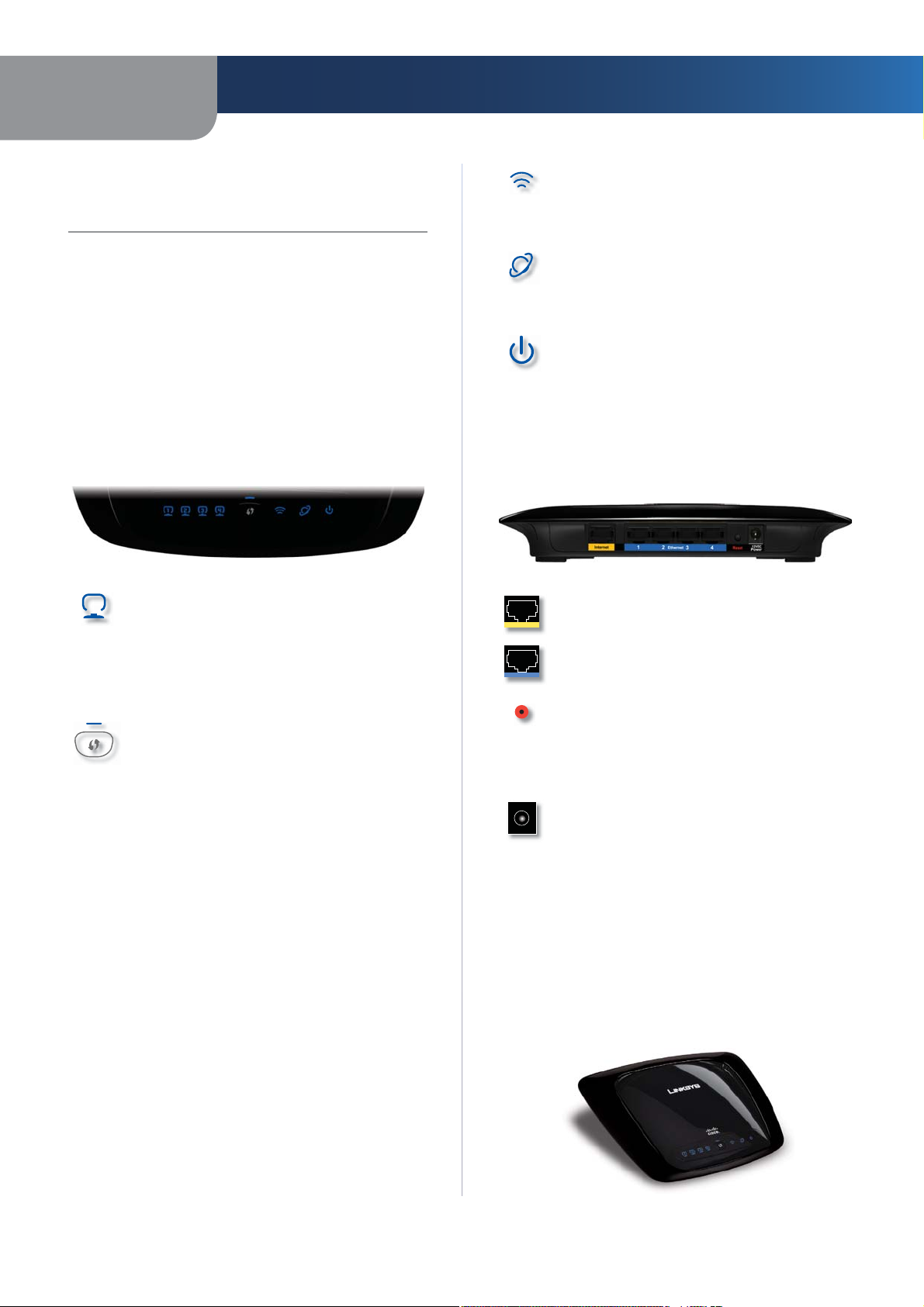
Front Panel
1, 2, 3, 4 (Blue) These numbered LEDs,
corresponding with the numbered ports on the
Router’s back panel, serve two purposes. If the
LED is continuously lit, the Router is successfully
connected to a device through that port. A
flashing LED indicates network activity over
that port.
Wi-Fi Protected Setup Button If you have
client devices, such as wireless adapters, that
support Wi-Fi Protected Setup, then you can
use Wi-Fi Protected Setup to automatically
configure wireless security for your wireless
network(s).
To use Wi-Fi Protected Setup, run the Setup
Wizard, or refer to the “Wireless > Basic Wireless
Settings” section of “Chapter 3: Advanced
Configuration”.
Wi-Fi Protected Setup LED (Blue/Amber) It
lights up blue when wireless security is
enabled. The LED flashes blue for two
minutes during Wi-Fi Protected Setup.
The LED lights up amber if there is an error
during the Wi-Fi Protected Setup process. Make
sure the client device supports Wi-Fi Protected
Setup. Wait until the LED is off, and then try again.
The LED flashes amber when a Wi-Fi Protected
Setup session is active, and a second session
begins. The Router supports one session at a
time. Wait until the LED is off before starting the
next Wi-Fi Protected Setup session.
Wireless (Blue) The Wireless LED lights up
when the wireless feature is enabled. If the LED
is flashing, the Router is actively sending or
receiving data over the network.
Internet (Blue) The Internet LED lights up
when there is a connection made through the
Internet port. A flashing LED indicates network
activity over the Internet port.
Power (Blue) The Power LED lights up and will
stay on while the Router is powered on. When
the Router goes through its self-diagnostic
mode during every boot-up, this LED will flash.
When the diagnostic is complete, the LED will
be solidly lit.
Back Panel
Internet The Internet port is where you will
connect your cable or DSL Internet connection.
1, 2, 3, 4 These Ethernet ports (1, 2, 3, 4) connect
the Router to PCs on your wired network and
other Ethernet network devices.
Reset There are two ways to reset the Router’s
factory defaults. Either press and hold the Reset
Button for approximately five seconds, or restore
the defaults from Administration > Factory
Defaults in the Router’s web-based utility.
Power The Power port is where you will
connect the power adapter.
Placement Positions
There are two ways to physically install the Router. The
first way is to place the Router horizontally on a surface.
The second way is to mount the Router on a wall.
Horizontal Placement
The Router has four rubber feet on its bottom panel. Place
the Router on a level surface near an electrical outlet.
Wireless-N Broadband Router
3
Page 6
Chapter 1
Product Overview
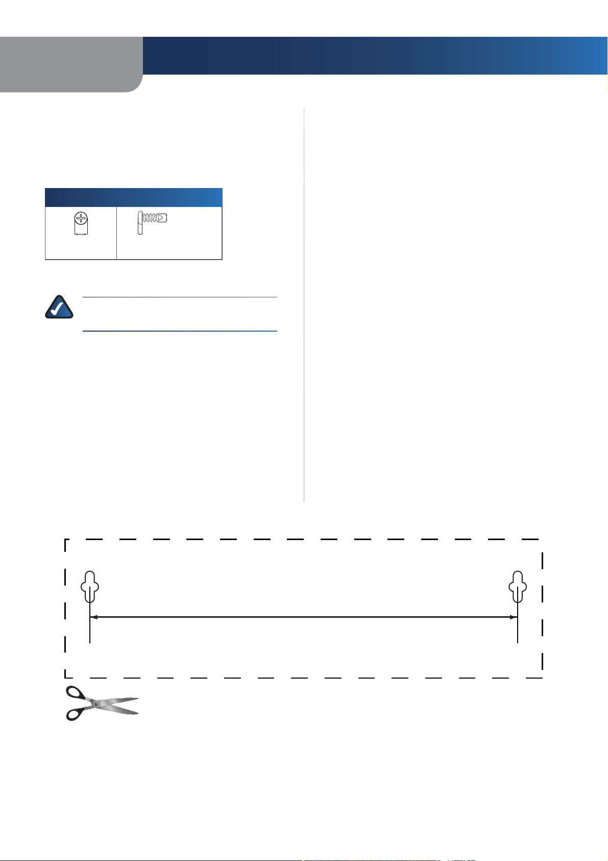
Wall-Mounting Placement
The Router has two wall-mount slots on its bottom
panel. The distance between the slots is 152 mm
(6 inches).
Two screws are needed to mount the Router.
Suggested Mounting Hardware
4-5 mm 1-1.5 mm
Note: Mounting hardware illustrations are not
†
true to scale.
NOTE: Linksys is not responsible for damages
incurred by insecure wall-mounting hardware.
2.5-3.0 mm
Follow these instructions:
Determine where you want to mount the Router. Make
1.
sure that the wall you use is smooth, flat, dry, and
sturdy. Also make sure the location is within reach of
an electrical outlet.
Drill two holes into the wall. Make sure the holes are
2.
152 mm (6 inches) apart.
Insert a screw into each hole and leave 3 mm
3.
(0.12 inches) of its head exposed.
Maneuver the Router so the wall-mount slots line up
4.
with the two screws.
Place the wall-mount slots over the screws and slide
5.
the Router down until the screws fit snugly into the
wall-mount slots.
Wireless-N Broadband Router
152 mm
Print this page at 100% size.
Cut along the dotted line, and place on the wall to drill precise spacing.
Wall Mounting Template
4
Page 7
Chapter 2
Wireless Security Checklist
Chapter 2:
Wireless Security Checklist
Wireless networks are convenient and easy to install, so
homes with high-speed Internet access are adopting them
at a rapid pace. Because wireless networking operates by
sending information over radio waves, it can be more
vulnerable to intruders than a traditional wired network.
Like signals from your cellular or cordless phones, signals
from your wireless network can also be intercepted. Since
you cannot physically prevent someone from connecting
to your wireless network, you need to take some additional
steps to keep your network secure.
1. Change the default wireless
network name or SSID
Wireless devices have a default wireless network name
or Service Set Identifier (SSID) set by the factory. This
is the name of your wireless network, and can be up
to 32 characters in length. Linksys wireless products
use linksys as the default wireless network name. You
should change the wireless network name to something
unique to distinguish your wireless network from other
wireless networks that may exist around you, but do not
use personal information (such as your Social Security
number) because this information may be available for
anyone to see when browsing for wireless networks.
2. Change the default password
For wireless products such as access points and routers,
you will be asked for a password when you want to change
their settings. These devices have a default password set
by the factory. The Linksys default password is admin.
Hackers know these defaults and may try to use them
to access your wireless device and change your network
settings. To thwart any unauthorized changes, customize
the device’s password so it will be hard to guess.
3. Enable MAC address filtering
Linksys routers give you the ability to enable Media Access
Control (MAC) address filtering. The MAC address is a
unique series of numbers and letters assigned to every
networking device. With MAC address filtering enabled,
wireless network access is provided solely for wireless
devices with specific MAC addresses. For example, you can
specify the MAC address of each computer in your home
so that only those computers can access your wireless
network.
4. Enable encryption
Encryption protects data transmitted over a wireless
network. Wi-Fi Protected Access (WPA/WPA2) and Wired
Equivalency Privacy (WEP) offer different levels of security
for wireless communication.
A network encrypted with WPA/WPA2 is more secure
than a network encrypted with WEP, because WPA/WPA2
uses dynamic key encryption. To protect the information
as it passes over the airwaves, you should enable the
highest level of encryption supported by your network
equipment.
WEP is an older encryption standard and may be the
only option available on some older devices that do not
support WPA.
General Network Security Guidelines
Wireless network security is useless if the underlying
network is not secure.
•
Password protect all computers on the network and
individually password protect sensitive files.
Change passwords on a regular basis.
•
•
Install anti-virus software and personal firewall
software.
•
Disable file sharing (peer-to-peer). Some applications
may open file sharing without your consent and/or
knowledge.
Additional Security Tips
•
Keep wireless routers, access points, or gateways away
from exterior walls and windows.
Turn wireless routers, access points, or gateways
•
off when they are not being used (at night, during
vacations).
•
Use strong passphrases that are at least eight characters
in length. Combine letters and numbers to avoid using
standard words that can be found in the dictionary.
WEB: For more information on wireless
security, visit www.linksys.com/security
Wireless-N Broadband Router
5
Page 8
Chapter 3
Chapter 3:
Advanced Configuration
After setting up the Router with the Setup Wizard (located
on the CD-ROM), the Router will be ready for use. However,
if you’d like to change its advanced settings, use the
Router’s web-based utility. This chapter describes each
web page of the utility and each page’s key functions. You
can access the utility via a web browser on a computer
connected to the Router.
The web-based utility has these main tabs: Setup,
Wireless, Security, Access Restrictions, Applications &
Gaming, Administration, and Status. Additional tabs will
be available after you click one of the main tabs.
NOTE: When first installing the Router, you
should use the Setup Wizard on the Setup
CD-ROM. If you want to configure advanced
settings, use this chapter to learn about the
web-based utility.
Advanced Configuration
Setup > Basic Setup
How to Access the Web-Based Utility
To access the web-based utility, launch the web browser on
your computer, and enter the Router’s default IP address,
192.168.1.1, in the Address field. Then, press Enter.
A login screen will appear. (Non-Windows XP users will
see a similar screen.) Leave the User name field blank. The
first time you open the Web-based utility, use the default
password admin. (You can set a new password from the
Administration tab’s Management screen.) Click OK to
continue.
Login Screen
Internet Setup
The Internet Setup section configures the Router to your
Internet connection. Most of this information can be
obtained through your ISP.
Internet Connection Type
Select the type of Internet connection your ISP provides
from the drop-down menu. These are the available types:
•
Automatic Configuration - DHCP
•
Static IP
•
PPPoE
•
PPTP
•
L2TP
•
Telstra Cable
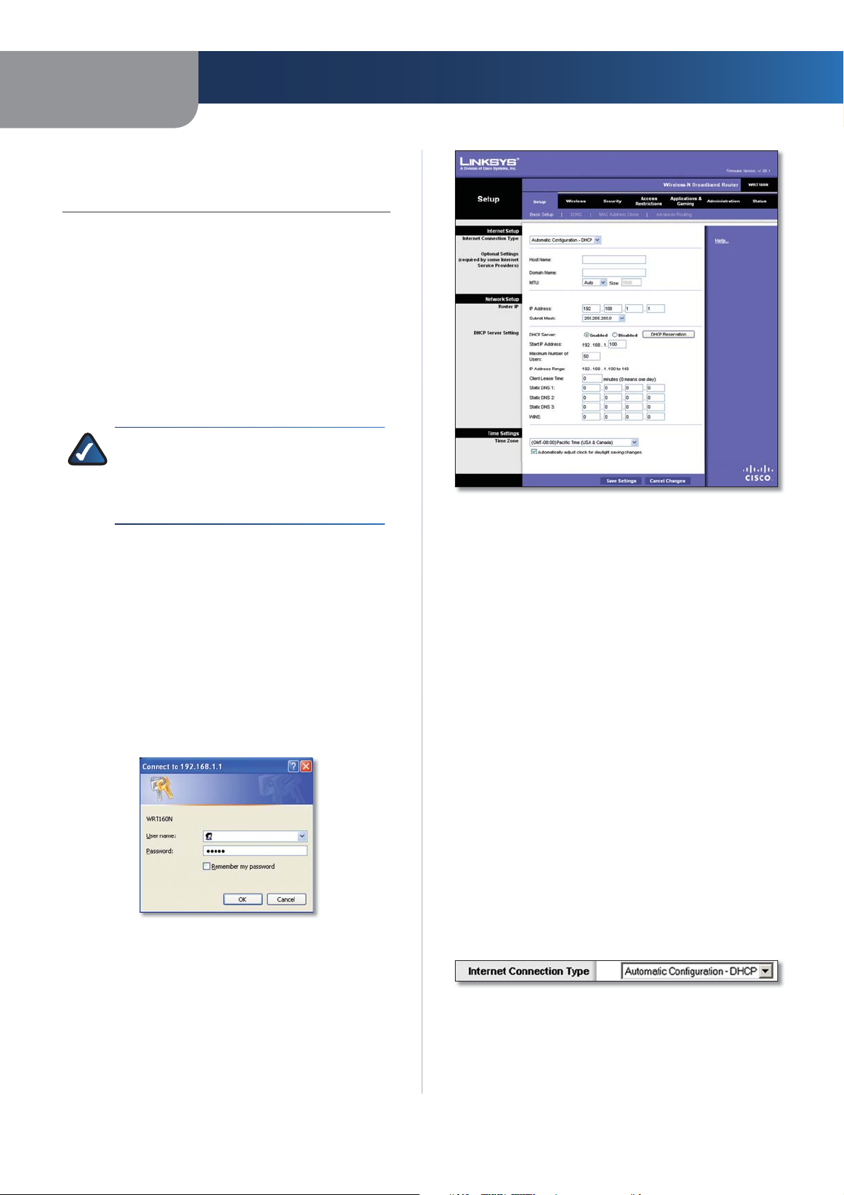
Automatic Configuration - DHCP
By default, the Router’s Internet Connection Type is set
to Automatic Configuration - DHCP, which should be
kept only if your ISP supports DHCP or you are connecting
through a dynamic IP address. (This option usually applies
to cable connections.)
Setup > Basic Setup
The first screen that appears is the Basic Setup screen. This
allows you to change the Router’s general settings.
Wireless-N Broadband Router
Internet Connection Type > Automatic Configuration - DHCP
6
Page 9
Chapter 3
Advanced Configuration
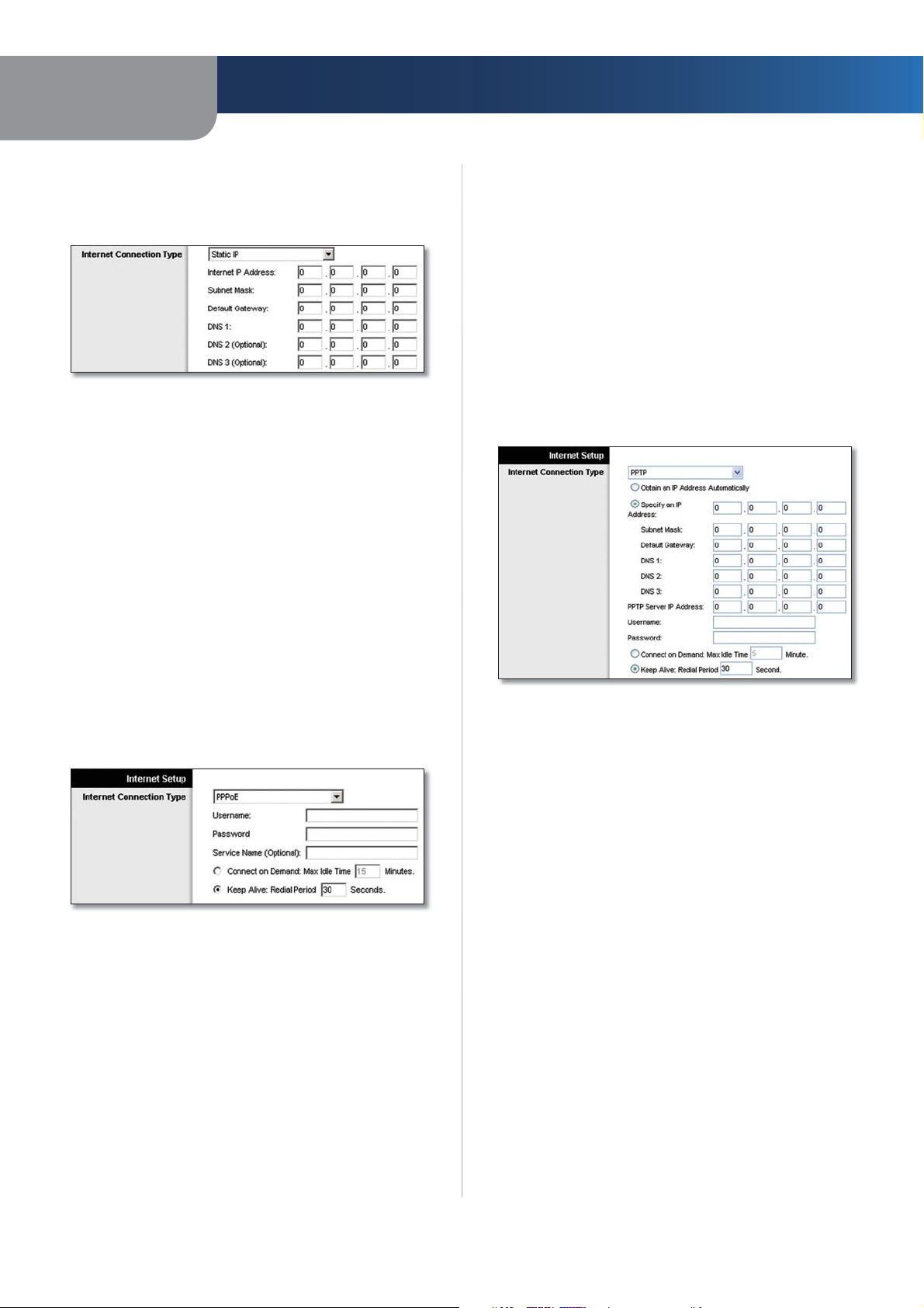
Static IP
If you are required to use a permanent IP address to
connect to the Internet, select Static IP.
Internet Connection Type > Static IP
Internet IP Address This is the Router’s IP address, when
seen from the Internet. Your ISP will provide you with the
IP Address you need to specify here.
Subnet Mask This is the Router’s Subnet Mask, as seen
by users on the Internet (including your ISP). Your ISP will
provide you with the Subnet Mask.
Default Gateway Your ISP will provide you with the IP
address of the ISP server.
DNS 1-3 Your ISP will provide you with at least one DNS
(Domain Name System) server IP address.
before your Internet connection terminates. The default
Max Idle Time is 15 minutes.
Keep Alive: Redial Period If you select this option,
the Router will periodically check your Internet
connection. If you are disconnected, then the Router
will automatically re-establish your connection. To use
this option, select Keep Alive. In the Redial Period field,
you specify how often you want the Router to check
the Internet connection. The default Redial Period is
30 seconds.
PPTP
Point-to-Point Tunneling Protocol (PPTP) is a service that
applies to connections in Europe only.
PPPoE
Some DSL-based ISPs use PPPoE (Point-to-Point Protocol
over Ethernet) to establish Internet connections. If you are
connected to the Internet through a DSL line, check with
your ISP to see if they use PPPoE. If they do, you will have
to enable PPPoE.
Internet Connection Type > PPPoE
Username and Password Enter the Username and
Password provided by your ISP.
Service Name If provided by your ISP, enter the Service
Name.
Connect on Demand: Max Idle Time You can configure
the Router to cut the Internet connection after it has been
inactive for a specified period of time (Max Idle Time). If
your Internet connection has been terminated due to
inactivity, Connect on Demand enables the Router to
automatically re-establish your connection as soon as you
attempt to access the Internet again. To use this option,
select Connect on Demand. In the Max Idle Time field,
enter the number of minutes you want to have elapsed
Internet Connection Type > PPTP
If your ISP supports DHCP or you are connecting through
a dynamic IP address, then select Obtain an IP Address
Automatically. If you are required to use a permanent IP
address to connect to the Internet, then select Specify an
IP Address. Then configure the following:
Specify an IP Address This is the Router’s IP address,
•
as seen from the Internet. Your ISP will provide you
with the IP Address you need to specify here.
•
Subnet Mask This is the Router’s Subnet Mask, as
seen by users on the Internet (including your ISP). Your
ISP will provide you with the Subnet Mask.
•
Default Gateway Your ISP will provide you with the
IP address of the ISP server.
DNS 1-3 Your ISP will provide you with at least one
•
DNS (Domain Name System) server IP address.
PPTP Server IP Address Your ISP will provide you with
the IP address of the PPTP server.
Username and Password Enter the Username and
Password provided by your ISP.
Connect on Demand: Max Idle Time You can configure
the Router to cut the Internet connection after it has been
inactive for a specified period of time (Max Idle Time). If
your Internet connection has been terminated due to
Wireless-N Broadband Router
7
Page 10
Chapter 3
Advanced Configuration
inactivity, Connect on Demand enables the Router to
automatically re-establish your connection as soon as you
attempt to access the Internet again. To use this option,
select Connect on Demand. In the Max Idle Time field,
enter the number of minutes you want to have elapsed
before your Internet connection terminates. The default
Max Idle Time is 15 minutes.
Keep Alive: Redial Period
Router will periodically check your Internet connection. If
you are disconnected, then the Router will automatically
re-establish your connection. To use this option, select
Keep Alive. In the Redial Period field, you specify how often
you want the Router to check the Internet connection. The
default value is 30 seconds.
If you select this option, the
L2TP
L2TP is a service that applies to connections in Israel only.
Internet Connection Type > L2TP
Server IP Address This is the IP address of the L2TP
Server. Your ISP will provide you with the IP Address you
need to specify here.
Username and Password Enter the Username and
Password provided by your ISP.
Connect on Demand: Max Idle Time You can configure
the Router to cut the Internet connection after it has been
inactive for a specified period of time (Max Idle Time). If
your Internet connection has been terminated due to
inactivity, Connect on Demand enables the Router to
automatically re-establish your connection as soon as you
attempt to access the Internet again. To use this option,
select Connect on Demand. In the Max Idle Time field,
enter the number of minutes you want to have elapsed
before your Internet connection terminates. The default
Max Idle Time is 15 minutes.
Keep Alive: Redial Period If you select this option,
the Router will periodically check your Internet
connection. If you are disconnected, then the Router
will automatically re-establish your connection. To use
this option, select Keep Alive. In the Redial Period field,
you specify how often you want the Router to check
the Internet connection. The default Redial Period is
30 seconds.
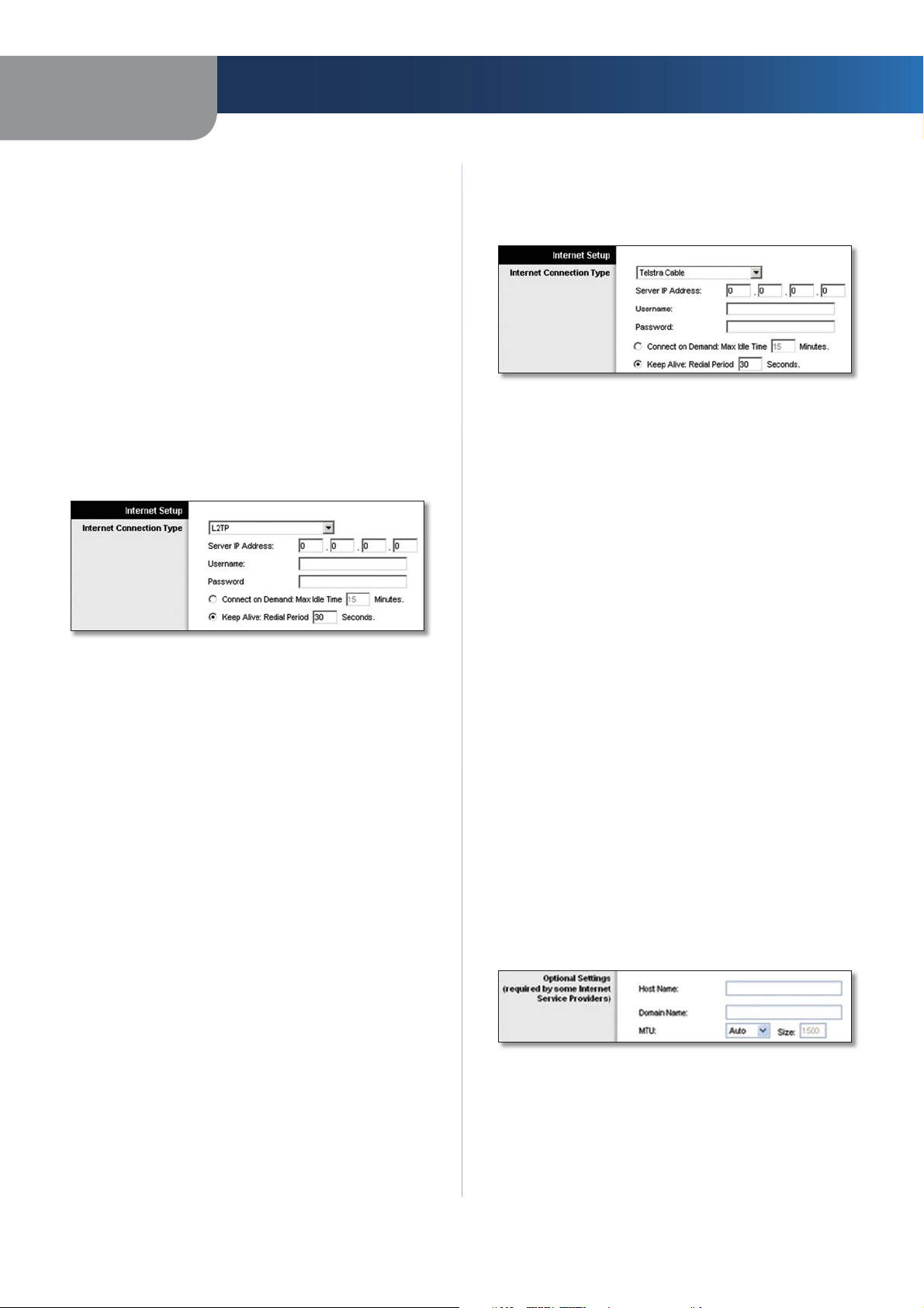
Telstra Cable
Telstra Cable is a service that applies to connections in
Australia only.
Internet Connection Type > Telstra Cable
Server IP Address This is the IP address of the Heartbeat
Server. Your ISP will provide you with the IP Address you
need to specify here.
Username and Password Enter the Username and
Password provided by your ISP.
Connect on Demand: Max Idle Time You can configure
the Router to cut the Internet connection after it has been
inactive for a specified period of time (Max Idle Time). If
your Internet connection has been terminated due to
inactivity, Connect on Demand enables the Router to
automatically re-establish your connection as soon as you
attempt to access the Internet again. To use this option,
select Connect on Demand. In the Max Idle Time field,
enter the number of minutes you want to have elapsed
before your Internet connection terminates. The default
Max Idle Time is 15 minutes.
Keep Alive: Redial Period If you select this option,
the Router will periodically check your Internet
connection. If you are disconnected, then the Router
will automatically re-establish your connection. To use
this option, select Keep Alive. In the Redial Period field,
you specify how often you want the Router to check
the Internet connection. The default Redial Period is
30 seconds.
Optional Settings
Some of these settings may be required by your ISP. Verify
with your ISP before making any changes.
Optional Settings
Host Name and Domain Name These fields allow you to
supply a host and domain name for the Router. Some ISPs,
usually cable ISPs, require these names as identification.
You may have to check with your ISP to see if your
broadband Internet service has been configured with a
Wireless-N Broadband Router
8
Page 11
Chapter 3
Advanced Configuration
host and domain name. In most cases, leaving these fields
blank will work.
MTU MTU is the Maximum Transmission Unit. It specifies
the largest packet size permitted for Internet transmission.
Select Manual if you want to manually enter the largest
packet size that is transmitted. To have the Router select
the best MTU for your Internet connection, keep the
default setting, Auto.
Size When Manual is selected in the MTU field, this option
is enabled. Leave this value in the 1200 to 1500 range. The
default size depends on the Internet Connection Type:
•
DHCP, Static IP, or Telstra: 1500
•
PPPoE: 1492
•
PPTP or L2TP: 1460
Network Setup
The Network Setup section changes the settings on the
network connected to the Router’s Ethernet ports. Wireless
setup is performed through the Wireless tab.
Router IP
This presents both the Router’s IP Address and Subnet
Mask as seen by your network.
Router IP
DHCP Server Setting
The settings allow you to configure the Router’s Dynamic
Host Configuration Protocol (DHCP) server function. The
Router can be used as a DHCP server for your network. A
DHCP server automatically assigns an IP address to each
computer on your network. If you choose to enable the
Router’s DHCP server option, make sure there is no other
DHCP server on your network.
DHCP Server Setting
DHCP Server DHCP is enabled by factory default. If you
already have a DHCP server on your network, or you don’t
want a DHCP server, then select Disabled (no other DHCP
features will be available).
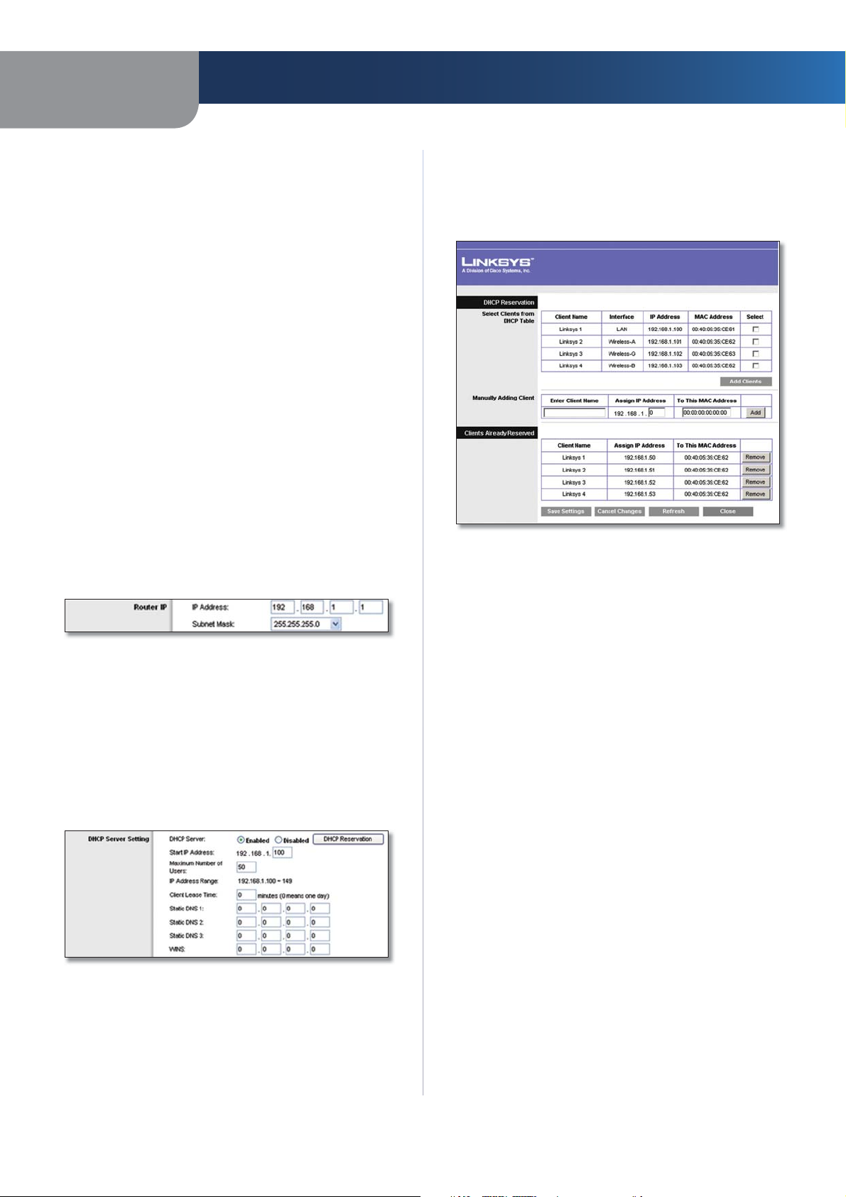
DHCP Reservation Click this button if you want to assign
a fixed local IP address to a MAC address.
Wireless-N Broadband Router
DHCP Reservation
You will see a list of DHCP clients with the following
information: Client Name, Interface, IP Address, and
MAC Address.
DHCP Reservation
Select Clients from DHCP Table Click the Select
•
check box to reserve a client’s IP address. Then click
Add Clients.
•
Manually Adding Client To manually assign an IP
address, enter the client’s name in the Enter Client
Name field. Enter the IP address you want it to have in
the Assign IP Address field. Enter its MAC address in the
To This MAC Address field. Then click Add.
Clients Already Reserved
A list of DHCP clients and their fixed local IP addresses
will be displayed at the bottom of the screen. If you
want to remove a client from this list, click Remove.
Click Save Settings to apply your changes, or click
Cancel Changes to cancel your changes. To view the
most up-to-date information, click Refresh. To exit this
screen, click Close.
Start IP Address Enter a value for the DHCP server to
start with when is
default IP address is 192.168.1.1, the Start IP Address must
be 192.168.1.2 or greater, but smaller than 192.168.1.253.
The default Starting IP Address is 192.168.1.100
Maximum Number of Users Enter the maximum
number of PCs that you want the DHCP server to assign
IP addresses to. This number cannot be greater than 253.
The default is 50.
IP Address Range Displayed here is the range of available
IP addresses.
suing IP addresses. Because the Router’s
.
9
Page 12
Chapter 3
Advanced Configuration
Client Lease Time The Client Lease Time is the amount
of time a network user will be allowed connection to the
Router with their current dynamic IP address. Enter the
amount of time, in minutes, that the user will be “leased”
this dynamic IP address. After the time is up, the user will
be automatically assigned a new dynamic IP address. The
default is 0 minutes, which means one day.
Static DNS 1-3
the Internet translates domain or website names into
Internet addresses or URLs. Your ISP will provide you with at
least one DNS Server IP Address. If you wish to use another,
enter that IP Address in one of these fields. You can enter up
to three DNS Server IP Addresses here. The Router will use
these for quicker access to functioning DNS servers
WINS The Windows Internet Naming Service (WINS)
manages each PC’s interaction with the Internet. If you
use a WINS server, enter that server’s IP Address here.
Otherwise, leave this blank.
The Domain Name System (DNS) is how
.
Time Setting
Time Zone Select the time zone in which your network
functions from this drop-down menu. (You can even
automatically adjust for daylight saving time.)
Time Setting
Click Save Settings to apply your changes, or click Cancel
Changes to cancel your changes.
Setup > DDNS
The Router offers a Dynamic Domain Name System (DDNS)
feature. DDNS lets you assign a fixed host and domain
name to a dynamic Internet IP address. It is useful when
you are hosting your own website, FTP server, or other
server behind the Router.
Before you can use this feature, you need to sign
up for DDNS service with a DDNS service provider,
www.dyndns.org or www.TZO.com. If you do not want to
use this feature, keep the default setting, Disabled.
DDNS
DDNS Service
If your DDNS service is provided by DynDNS.org, then
select DynDNS.org from the drop-down menu. If your
DDNS service is provided by TZO, then select TZO.com.
The features available on the DDNS screen will vary,
depending on which DDNS service provider you use.
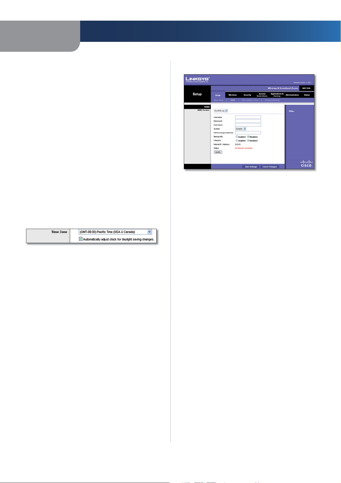
DynDNS.org
Setup > DDNS > DynDNS
Username Enter the Username for your DDNS account.
Password Enter the Password for your DDNS account.
Host Name The is the DDNS URL assigned by the DDNS
service.
System Select the DynDNS service you use: Dynamic,
Static, or Custom. The default selection is Dynamic.
Mail Exchange (Optional) Enter the address of your mail
exchange server, so e-mails to your DynDNS address go to
your mail server.
Backup MX This feature allows the mail exchange server
to be a backup. To disable this feature, keep the default,
Disabled. To enable the feature, select Enabled. If you
are not sure which setting to select, keep the default,
Disabled.
Wildcard This setting enables or disables wildcards
for your host. For example, if your DDNS address is
myplace.dyndns.org and you enable wildcards, then
x.myplace.dyndns.org will work as well (x is the wildcard).
To disable wildcards, keep the default, Disabled. To enable
wildcards, select Enabled. If you are not sure which setting
to select, keep the default, Disabled.
Internet IP Address The Router’s Internet IP address is
displayed here. Because it is dynamic, it will change.
Status The status of the DDNS service connection is
displayed here.
Update To manually trigger an update, click this button.
Click Save Settings to apply your changes, or click Cancel
Changes to cancel your changes.
Wireless-N Broadband Router
10
Page 13
Chapter 3
Advanced Configuration
TZO.com
Setup > DDNS > TZO
E-mail Address, TZO Key, and Domain Name Enter the
settings of the account you set up with TZO.
Internet IP Address The Router’s Internet IP address is
displayed here. Because it is dynamic, it will change.
Status The status of the DDNS service connection is
displayed here.
Update To manually trigger an update, click this button.
Click Save Settings to apply your changes, or click Cancel
Changes to cancel your changes.
Clone My PC’s MAC Click this button to clone the MAC
address of the computer you are using.
Click Save Settings to apply your changes, or click Cancel
Changes to cancel your changes.
Setup > Advanced Routing
This screen is used to set up the Router’s advanced
functions. Operating Mode allows you to select the
type(s) of advanced functions you use. Dynamic Routing
automatically adjusts how packets travel on your network.
Static Routing sets up a fixed route to another network
destination.
Setup > MAC Address Clone
A MAC address is a 12-digit code assigned to a unique
piece of hardware for identification. Some ISPs will require
you to register a MAC address in order to access the
Internet. If you do not wish to re-register the MAC address
with your ISP, you may assign the MAC address you have
currently registered with your ISP to the Router with the
MAC Address Clone feature.
Setup > MAC Address Clone
MAC Address Clone
Enabled/Disabled To have the MAC Address cloned,
select Enabled.
MAC Address Enter the MAC Address registered with
your ISP here.
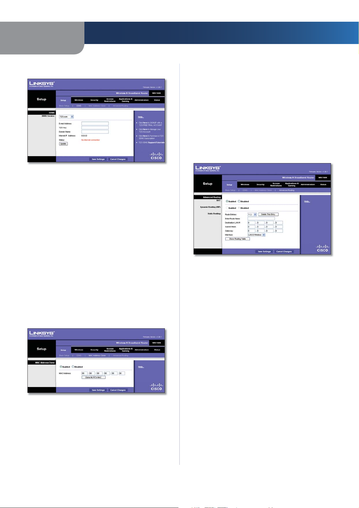
Setup > Advanced Routing
Advanced Routing
NAT
Enabled/Disabled If this Router is hosting your network’s
connection to the Internet, keep the default, Enabled. If
another router exists on your network, select Disabled.
When the NAT setting is disabled, dynamic routing will be
enabled.
Dynamic Routing (RIP)
Enabled/Disabled This feature enables the Router to
automatically adjust to physical changes in the network’s
layout and exchange routing tables with the other router(s).
The Router determines the network packets’ route based
on the fewest number of hops between the source and
the destination. When the NAT setting is enabled, the
Dynamic Routing feature is automatically disabled. When
the NAT setting is disabled, this feature is available. Select
Enabled to use the Dynamic Routing feature.
Static Routing
A static route is a pre-determined pathway that network
information must travel to reach a specific host or network.
Enter the information described below to set up a new
static route.
Wireless-N Broadband Router
11
Page 14
Chapter 3
Advanced Configuration
Route Entries To set up a static route between the Router
and another network, select a number from the dropdown list. Click Delete This Entry to delete a static route.
Enter Route Name Enter a name for the Route here,
using a maximum of 25 alphanumeric characters.
Destination LAN IP The Destination LAN IP is the address
of the remote network or host to which you want to assign
a static route.
Subnet Mask The Subnet Mask determines which
portion of a Destination LAN IP address is the network
portion, and which portion is the host portion.
Gateway This is the IP address of the gateway device that
allows for contact between the Router and the remote
network or host.
Interface This interface tells you whether the Destination
IP Address is on the LAN & Wireless (Ethernet and wireless
networks) or the WAN (Internet).
Click Show Routing Table to view the static routes you
have already set up.
Advanced Routing > Routing Table
Routing Table
For each route, the Destination LAN IP address, Subnet
Mask, Gateway, and Interface are displayed. Click
Refresh to update the information. Click Close to exit
this screen.
Click Save Settings to apply your changes, or click Cancel
Changes to cancel your changes.
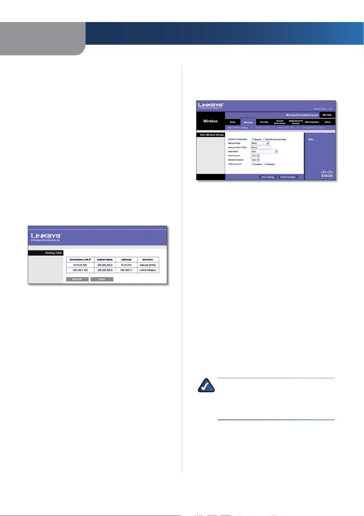
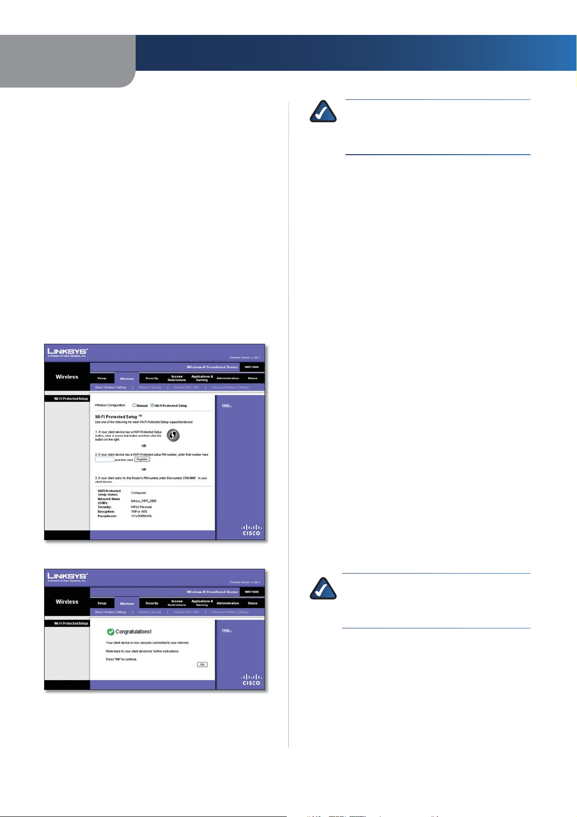
Wireless > Basic Wireless Settings
select Wi-Fi Protected Setup. Proceed to the “Wi-Fi
Protected Setup” section.
Basic Wireless Settings
Wireless > Basic Wireless Settings (Manual Setup)
Network Mode From this drop-down menu, you can
select the wireless standards running on your network. If
you have Wireless-N, Wireless-G, and Wireless-B devices in
your network, keep the default setting, Mixed. If you have
only Wireless-G and Wireless-B devices in your network,
select BG-Mixed. If you have only Wireless-N devices,
select Wireless-N Only. If you have only Wireless-G
devices, select Wireless-G Only. If you have only WirelessB devices, select Wireless-B Only. If you do not have any
wireless devices in your network, select Disabled.
Network Name (SSID) The SSID is the network name
shared among all points in a wireless network. The
SSID must be identical for all devices in the wireless
network. It is case-sensitive and must not exceed
32 characters (use any of the characters on the keyboard).
Make sure this setting is the same for all points in your
wireless network. For added security, you should change
the default SSID (linksys) to a unique name.
Radio Band For best performance in a network using
Wireless-N, Wireless-G and Wireless-B devices, keep the
default, Wide - 40MHz Channel. For Wireless-G and
Wireless-B networking only, select Standard - 20MHz
Channel. If you are not sure which radio band to select,
keep the default, Auto.
The basic settings for wireless networking are set on this
screen.
There are two ways to configure the Router’s wireless
network(s), manual and Wi-Fi Protected Setup.
Wi-Fi Protected Setup is a feature that makes it easy to set
up your wireless network. If you have client devices, such
as wireless adapters, that support Wi-Fi Protected Setup,
then you can use Wi-Fi Protected Setup.
Wireless Configuration To manually configure your
wireless network, select Manual. Proceed to the “Basic
Wireless Settings” section. To use Wi-Fi Protected Setup,
Wireless-N Broadband Router
NOTE: If you select Wide - 40MHz Channel for
the Radio Band setting, then Wireless-N can use
two channels: a primary one (Wide Channel)
and a secondary one (Standard Channel). This
will enhance Wireless-N performance.
Wide Channel If you selected Wide - 40MHz Channel for
the Radio Band setting, then this setting will be available
for your primary Wireless-N channel. Select any channel
from the drop-down menu. If you are not sure which
channel to select, keep the default, Auto.
12
Page 15
Chapter 3
Advanced Configuration
Standard Channel If you selected Wide - 40MHz Channel
or Standard - 20MHz Channel for the Radio Band setting,
then this setting will be available. Select the channel for
Wireless-N, Wireless-G, and Wireless-B networking. If
you selected Wide – 40MHz Channel for the Radio Band
setting, then the Standard Channel will be a secondary
channel for Wireless-N.
SSID Broadcast When wireless clients survey the local
area for wireless networks to associate with, they will
detect the SSID broadcast by the Router. To broadcast the
Router’s SSID, keep the default setting, Enabled. If you
do not want to broadcast the Router’s SSID, then select
Disabled.
Click Save Settings to apply your changes, or click Cancel
Changes to cancel your changes.
Wi-Fi Protected Setup
There are three methods available. Use the method that
applies to the client device you are configuring.
NOTE: Wi-Fi Protected Setup configures one
client device at a time. Repeat the instructions
for each client device that supports Wi-Fi
Protected Setup.
Method #1
Use this method if your client device has a Wi-Fi Protected
Setup button.
1.
Click or press the Wi-Fi Protected Setup button on
the client device.
2.
Click the Wi-Fi Protected Setup button on this
screen.
3.
After the client device has been configured, click
OK. Then refer back to your client device or its
documentation for further instructions.
Method #2
Use this method if your client device has a Wi-Fi Protected
Setup PIN number.
1.
Enter the PIN number in the field on this screen.
2.
Click Register.
3.
After the client device has been configured, click
OK. Then refer back to your client device or its
documentation for further instructions.
Wireless > Basic Wireless Settings (Wi-Fi Protected Setup)
Wi-Fi Protected Setup > Congratulations
Method #3
Use this method if your client device asks for the Router’s
PIN number.
1.
Enter the PIN number listed on this screen. (It is also
listed on the label on the bottom of the Router.)
2.
After the client device has been configured, click
OK. Then refer back to your client device or its
documentation for further instructions.
The Wi-Fi Protected Setup Status, Network Name (SSID),
Security, Encryption, and Passphrase are displayed at the
bottom of the screen.
NOTE: If you have client devices that do not
support Wi-Fi Protected Setup, note the wireless
settings, and then manually configure those
client devices.
Wireless > Wireless Security
The Wireless Security screen configures the security of
your wireless network. There are six wireless security
mode options supported by the Router: WPA Personal,
WPA Enterprise, WPA2 Personal, WPA2 Enterprise, RADIUS,
and WEP. (WPA stands for Wi-Fi Protected Access, which
is a security standard stronger than WEP encryption. WEP
stands for Wired Equivalent Privacy, while RADIUS stands
Wireless-N Broadband Router
13
Page 16
Chapter 3
Advanced Configuration
for Remote Authentication Dial-In User Service.) These
six are briefly discussed here. For detailed instructions
on configuring wireless security for the Router, refer to
“Chapter 2: Wireless Security.”
Wireless Security
Security Mode
Select the security method for your wireless network. If
you do not want to use wireless security, keep the default,
Disabled.
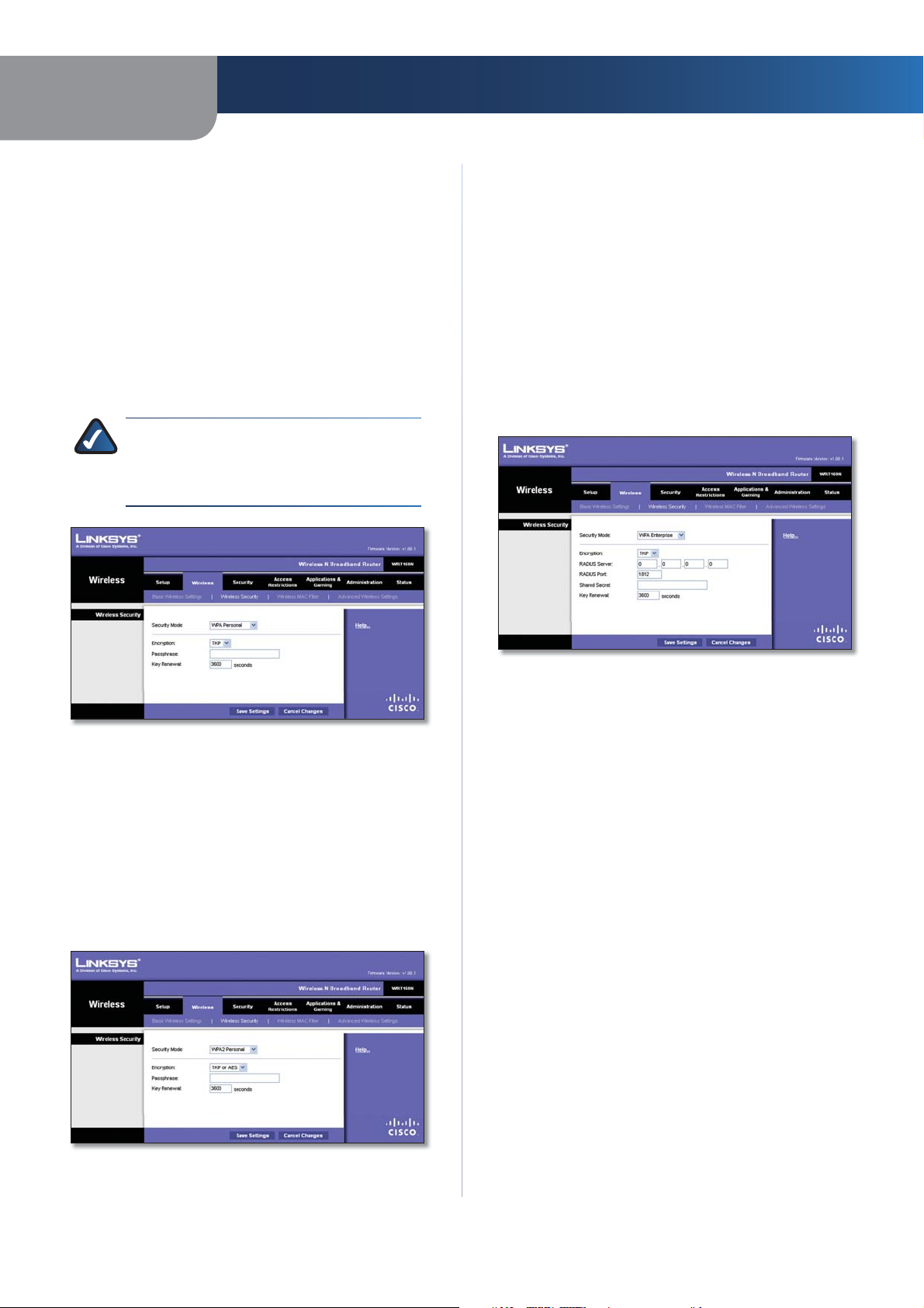
WPA Personal
NOTE: If you are using WPA, always remember
that each device in your wireless network MUST
use the same WPA method and shared key, or
else the network will not function properly.
Encryption WPA2 supports two encryption methods,
TKIP and AES, with dynamic encryption keys. Select the
type of algorithm, AES or TKIP or AES. The default is TKIP
or AES.
Passphrase Enter a Passphrase of 8-63 characters.
Key Renewal Enter a Key Renewal period, which instructs
the Router how often it should change the encryption keys.
The default Group Key Renewal period is 3600 seconds.
WPA Enterprise
This option features WPA used in coordination with a
RADIUS server. (This should only be used when a RADIUS
server is connected to the Router.)
Security Mode > WPA Personal
Encryption WPA supports two encryption methods, TKIP
and AES, with dynamic encryption keys. Select the type of
algorithm, TKIP or AES. The default is TKIP.
Passphrase Enter a Passphrase of 8-63 characters.
Key Renewal Enter a Key Renewal period, which instructs
the Router how often it should change the encryption keys.
The default Group Key Renewal period is 3600 seconds.
WPA2 Personal
Security Mode > WPA Enterprise
Encryption WPA supports two encryption methods, TKIP
and AES, with dynamic encryption keys. Select the type of
algorithm, TKIP or AES. The default is TKIP.
RADIUS Server Enter the IP Address of the RADIUS
server.
RADIUS Port Enter the port number of the RADIUS
server. The default value is 1812.
Shared Secret Enter the key shared between the Router
and the server.
Key Renewal Enter a Key Renewal period, which instructs
the Router how often it should change the encryption
keys. The default Key Renewal period is 3600 seconds.
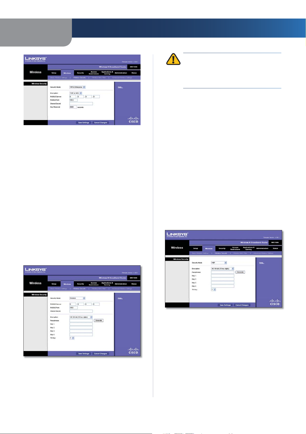
WPA2 Enterprise
This option features WPA2 used in coordination with a
RADIUS server. (This should only be used when a RADIUS
server is connected to the Router.)
Security Mode > WPA2 Personal
Wireless-N Broadband Router
14
Page 17
Chapter 3
Security Mode > WPA2 Enterprise
Encryption WPA2 supports two encryption methods,
TKIP and AES, with dynamic encryption keys. Select the
type of algorithm, AES or TKIP or AES. The default is TKIP
or AES.
RADIUS Server Enter the IP Address of the RADIUS
server.
RADIUS Port Enter the port number of the RADIUS
server. The default value is 1812.
Shared Secret Enter the key shared between the Router
and the server.
Key Renewal Enter a Key Renewal period, which instructs
the Router how often it should change the encryption
keys. The default Key Renewal period is 3600 seconds.
Advanced Configuration
IMPORTANT: If you are using WEP encryption,
always remember that each device in your
wireless network MUST use the same WEP
encryption method and encryption key, or else
your wireless network will not function properly.
RADIUS Server Enter the IP Address of the RADIUS
server.
RADIUS Port Enter the port number of the RADIUS
server. The default value is 1812.
Shared Secret Enter the key shared between the Router
and the server.
Encryption Select a level of WEP encryption,
40/64 bits (10 hex digits) or 104/128 bits (26 hex digits).
The default is 40/64 bits (10 hex digits).
Passphrase Enter a Passphrase to automatically generate
WEP keys. Then click Generate.
Key 1-4 If you did not enter a Passphrase, enter the WEP
key(s) manually.
TX Key Select which TX (Transmit) Key to use. The default
is 1.
WEP
WEP is a basic encryption method, which is not as secure
as WPA.
RADIUS
This option features WEP used in coordination with a
RADIUS server. (This should only be used when a RADIUS
server is connected to the Router.)
Security Mode > RADIUS
Wireless-N Broadband Router
Security Mode > WEP
Encryption Select a level of WEP encryption,
40/64 bits (10 hex digits) or 104/128 bits (26 hex digits).
The default is 40/64 bits (10 hex digits).
Passphrase Enter a Passphrase to automatically generate
WEP keys. Then click Generate.
Key 1-4 If you did not enter a Passphrase, enter the WEP
key(s) manually.
TX Key Select which TX (Transmit) Key to use. The default
is 1.
Click Save Settings to apply your changes, or click Cancel
Changes to cancel your changes.
15
Page 18
Chapter 3
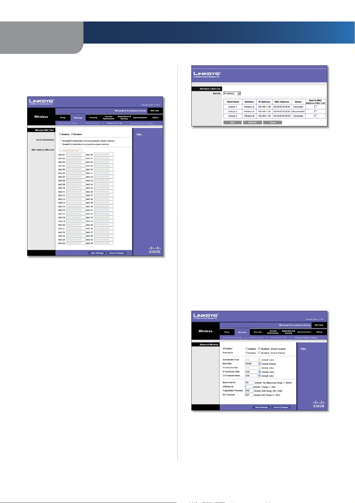
Wireless > Wireless MAC Filter
Wireless access can be filtered by using the MAC addresses of
the wireless devices transmitting within your network’s radius.
Wireless > Wireless MAC Filter
Wireless MAC Filter
Enabled/Disabled
either permitting or blocking access, select Enabled. If you
do not wish to filter users by MAC Address, keep the default
setting, Disabled
To filter wireless users by MAC Address,
.
Advanced Configuration
Wireless Client List
Wireless Client List
This screen shows computers and other devices on
the wireless network. The list can be sorted by Client
Name, Interface, IP Address, MAC Address, and Status.
Select Save to MAC Address Filter List for any device
you want to add to the MAC Address Filter List. Then
click Add.
To retrieve the most up-to-date information, click
Refresh. To exit this screen and return to the Wireless
MAC Filter screen, click Close.
MAC 01-50 Enter the MAC addresses of the devices
whose wireless access you want to block or allow.
Click Save Settings to apply your changes, or click Cancel
Changes to cancel your changes.
Wireless > Advanced Wireless Settings
This Advanced Wireless Settings screen is used to set up
the Router’s advanced wireless functions. These settings
should only be adjusted by an expert administrator as
incorrect settings can reduce wireless performance.
Access Restriction
Prevent Select this to block wireless access by MAC
Address. This button is selected by default.
Permit Select this to allow wireless access by MAC
Address. This button is not selected by default.
MAC Address Filter List
Wireless Client List Click this to open the Wireless Client
List screen.
Wireless-N Broadband Router
Wireless > Advanced Wireless Settings
Advanced Wireless
AP Isolation This isolates all wireless clients and wireless
devices on your network from each other. Wireless devices
will be able to communicate with the Router but not
16
Page 19
Chapter 3
Advanced Configuration
with each other. To use this function, select Enabled. AP
Isolation is disabled by default.
Frame Burst Enabling this option should provide your
network with greater performance, depending on the
manufacturer of your wireless products. To use this option,
keep the default, Enabled. Otherwise, select Disabled.
Authentication Type The default is set to Auto, which
allows either Open System or Shared Key authentication
to be used. With Open System authentication, the sender
and the recipient do NOT use a WEP key for authentication.
With Shared Key authentication, the sender and recipient
use a WEP key for authentication. Select Shared Key to
only use Shared Key authentication.
Basic Rate The Basic Rate setting is not actually one rate
of transmission but a series of rates at which the Router
can transmit. The Router will advertise its Basic Rate to the
other wireless devices in your network, so they know which
rates will be used. The Router will also advertise that it will
automatically select the best rate for transmission. The
default setting is Default, when the Router can transmit
at all standard wireless rates (1-2Mbps, 5.5Mbps, 11Mbps,
18Mbps, and 24Mbps). Other options are 1-2Mbps, for
use with older wireless technology, and All, when the
Router can transmit at all wireless rates. The Basic Rate
is not the actual rate of data transmission. If you want to
specify the Router’s rate of data transmission, configure
the Transmission Rate setting.
Transmission Rate The rate of data transmission should
be set depending on the speed of your wireless network.
You can select from a range of transmission speeds, or you
can select Auto to have the Router automatically use the
fastest possible data rate and enable the Auto-Fallback
feature. Auto-Fallback will negotiate the best possible
connection speed between the Router and a wireless
client. The default is Auto.
N Transmission Rate The rate of data transmission
should be set depending on the speed of your Wireless-N
networking. You can select from a range of transmission
speeds, or you can select Auto to have the Router
automatically use the fastest possible data rate and enable
the Auto-Fallback feature. Auto-Fallback will negotiate the
best possible connection speed between the Router and a
wireless client. The default is Auto.
CTS Protection Mode The Router will automatically
use CTS (Clear-To-Send) Protection Mode when your
Wireless-N and Wireless-G products are experiencing
severe problems and are not able to transmit to the
Router in an environment with heavy 802.11b traffic. This
function boosts the Router’s ability to catch all WirelessN and Wireless-G transmissions but will severely decrease
performance. The default is Auto.
Beacon Interval Enter a value between 1 and 65,535
milliseconds. The Beacon Interval value indicates the
frequency interval of the beacon. A beacon is a packet
Wireless-N Broadband Router
broadcast by the Router to synchronize the wireless
network. The default value is 100.
DTIM Interval This value, between 1 and 255, indicates
the interval of the Delivery Traffic Indication Message
(DTIM). A DTIM field is a countdown field informing
clients of the next window for listening to broadcast
and multicast messages. When the Router has buffered
broadcast or multicast messages for associated clients, it
sends the next DTIM with a DTIM Interval value. Its clients
hear the beacons and awaken to receive the broadcast
and multicast messages. The default value is 1.
Fragmentation Threshold This value specifies the
maximum size for a packet before data is fragmented
into multiple packets. If you experience a high packet
error rate, you may slightly increase the Fragmentation
Threshold. Setting the Fragmentation Threshold too low
may result in poor network performance. Only minor
reduction of the default value is recommended. In most
cases, it should remain at its default value of 2346.
RTS Threshold Should you encounter inconsistent data
flow, only minor reduction of the default value, 2347, is
recommended. If a network packet is smaller than the
preset RTS threshold size, the RTS/CTS mechanism will
not be enabled. The Router sends Request to Send (RTS)
frames to a particular receiving station and negotiates
the sending of a data frame. After receiving an RTS, the
wireless station responds with a Clear to Send (CTS) frame
to acknowledge the right to begin transmission. The RTS
Threshold value should remain at its default value of
2347.
Click Save Settings to apply your changes, or click Cancel
Changes to cancel your changes.
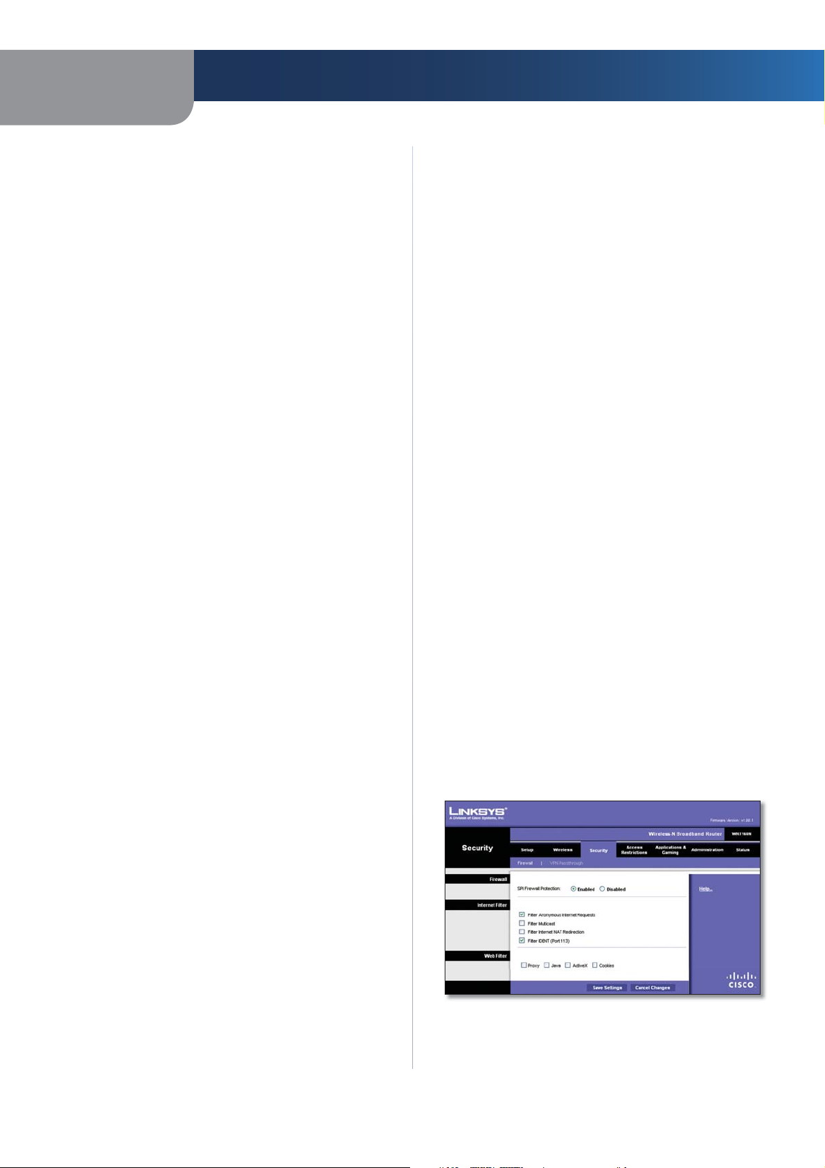
Security > Firewall
The Firewall screen is used to configure a firewall that can
filter out various types of unwanted traffic on the Router’s
local network.
Security > Firewall
17
Page 20
Chapter 3
Advanced Configuration
Firewall
SPI Firewall Protection To use firewall protection,
keep the default selection, Enabled. To turn off firewall
protection, select Disabled.
Internet Filter
Filter Anonymous Internet Requests This feature
makes it more difficult for outside users to work their
way into your network. This feature is selected by default.
Deselect the feature to allow anonymous Internet
requests
Filter Multicast Multicasting allows for multiple
transmissions to specific recipients at the same time. If
multicasting is permitted, then the Router will allow IP
multicast packets to be forwarded to the appropriate
computers. Select this feature to filter multicasting. This
feature is not selected by default.
Filter Internet NAT Redirection This feature uses port
forwarding to block access to local servers from local
networked computers. Select this feature to filter Internet
NAT redirection. It is not selected by default.
Filter IDENT (Port 113) This feature keeps port 113 from
being scanned by devices outside of your local network.
This feature is selected by default. Deselect this feature to
disable it.
.
Web Filter
Proxy Use of WAN proxy servers may compromise the
Gateway’s security. Denying Proxy will disable access to
any WAN proxy servers. Select this feature to enable proxy
filtering. Deselect the feature to allow proxy access
Java Java is a programming language for websites. If you
deny Java, you run the risk of not having access to Internet
sites created using this programming language. Select
this feature to enable Java filtering. Deselect the feature
to allow Java usage
ActiveX ActiveX is a programming language for websites.
If you deny ActiveX, you run the risk of not having access to
Internet sites created using this programming language.
Select this feature to enable ActiveX filtering. Deselect the
feature to allow ActiveX usage
Cookies A cookie is data stored on your computer and
used by Internet sites when you interact with them. Select
this feature to filter cookies. Deselect the feature to allow
cookie usage
Click Save Settings to apply your changes, or click Cancel
Changes to cancel your changes.
.
.
.
.
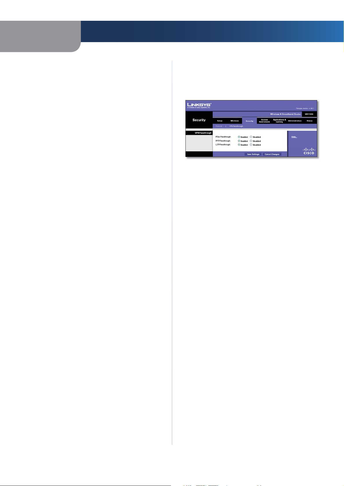
Security > VPN Passthrough
The VPN Passthrough screen allows you to enable VPN
tunnels using IPSec, PPTP, or L2TP protocols to pass through
the Router’s firewall.
Security > VPN Passthrough
VPN Passthrough
IPSec Passthrough Internet Protocol Security (IPSec) is
a suite of protocols used to implement secure exchange
of packets at the IP layer. To allow IPSec tunnels to pass
through the Router, keep the default, Enabled.
PPTP Passthrough Point-to-Point Tunneling Protocol
(PPTP) allows the Point-to-Point Protocol (PPP) to be
tunneled through an IP network. To allow PPTP tunnels to
pass through the Router, keep the default, Enabled.
L2TP Passthrough Layer 2 Tunneling Protocol is the
method used to enable Point-to-Point sessions via the
Internet on the Layer 2 level. To allow L2TP tunnels to pass
through the Router, keep the default, Enabled.
Click Save Settings to apply your changes, or click Cancel
Changes to cancel your changes.
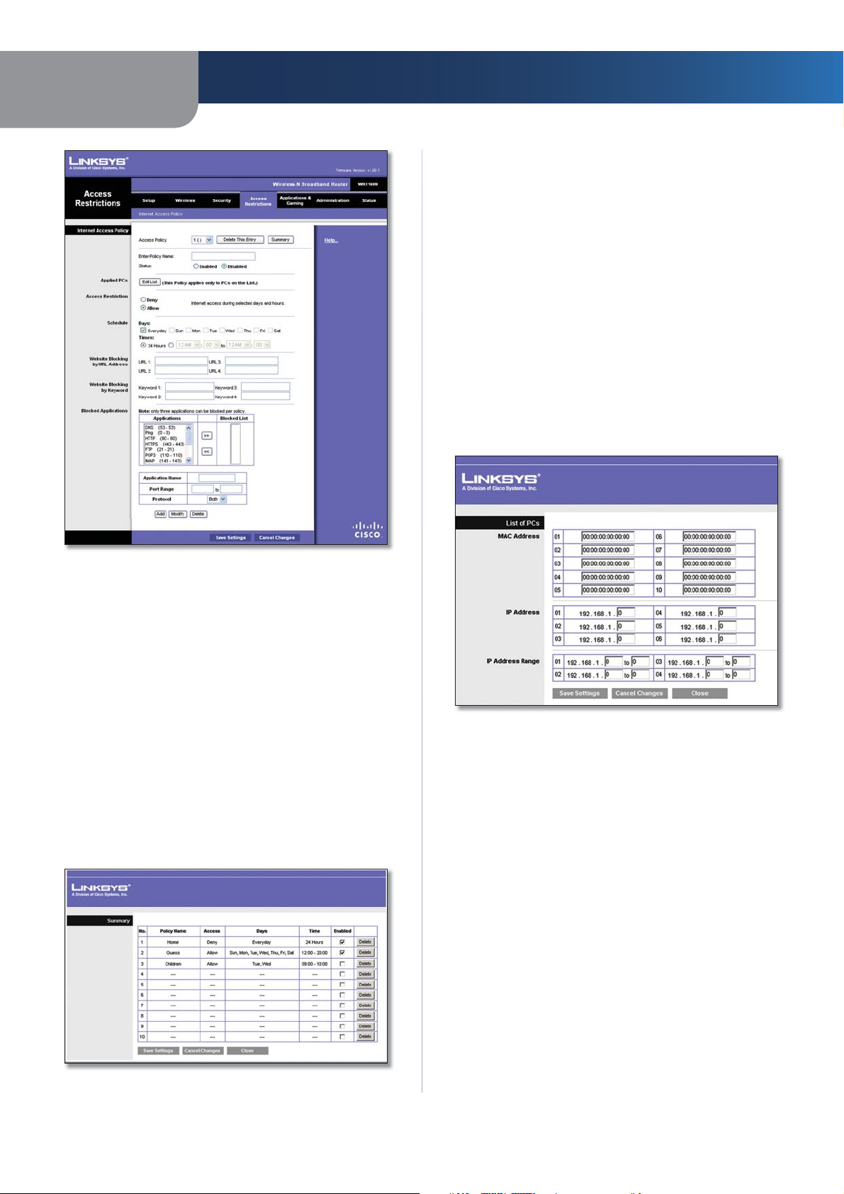
Access Restrictions > Internet Access
The Internet Access screen allows you to block or allow
specific kinds of Internet usage and traffic, such as Internet
access, designated services, and websites during specific
days and times.
Wireless-N Broadband Router
18
Page 21
Chapter 3
Advanced Configuration
Status Policies are disabled by default. To enable a policy,
select the policy number from the drop-down menu, and
select Enabled.
To create a policy, follow steps 1-11. Repeat these steps to
create additional policies, one at a time.
1.
Select a number from the Access Policy drop-down
menu.
2.
Enter a Policy Name in the field provided.
3.
To enable this policy, select Enabled.
4.
Click Edit List to select which PCs will be affected by
the policy. The List of PCs screen appears. You can
select a PC by MAC address or IP address. You can also
enter a range of IP addresses if you want this policy to
affect a group of PCs. After making your changes, click
Save Settings to apply your changes, or click Cancel
Changes to cancel your changes. Then click Close.
Access Restrictions > Internet Access
Internet Access Policy
Access Policy Access can be managed by a policy. Use the
settings on this screen to establish an access policy (after
Save Settings is clicked). Selecting a policy from the dropdown menu will display that policy’s settings. To delete a
policy, select that policy’s number and click Delete This
Policy. To view all the policies, click Summary.
Summary
The policies are listed with the following information: No.,
Policy Name, Access, Days, Time, and status (Enabled). To
enable a policy, select Enabled. To delete a policy, click
Delete. Click Save Settings to save your changes, or click
Cancel Changes to cancel your changes. To return to the
Internet Access Policy screen, click Close.
List of PCs
Select the appropriate option, Deny or Allow,
5.
depending on whether you want to block or allow
Internet access for the PCs you listed on the List of PCs
screen.
Decide which days and what times you want this policy
6.
to be enforced. Select the individual days during which
the policy will be in effect, or select Everyday. Then
enter a range of hours and minutes during which the
policy will be in effect, or select 24 Hours.
You can block websites with specific URL addresses.
7.
Enter each URL in a separate URL field.
You can also block websites using specific keywords.
8.
Enter each keyword in a separate Keyword field.
Wireless-N Broadband Router
Summary
19
Page 22

Chapter 3
You can filter access to various services accessed
9.
over the Internet, such as FTP or telnet. (You
can block up to three applications per policy.)
From the Applications list, select the application you
want to block. Then click the >> button to move it to
the Blocked List. To remove an application from the
Blocked List, select it and click the << button.
If the application you want to block is not listed
10.
or you want to edit a service’s settings, enter the
application’s name in the Application Name field. Enter
its range in the Port Range fields. Select its protocol
from the Protocol drop-down menu. Then click Add.
To modify a service, select it from the
Application list. Change its name, port range,
and/or protocol setting. Then click Modify.
To delete a service, select it from the Application list.
Then click Delete.
Click Save Settings to save the policy’s settings. To
11.
cancel the policy’s settings, click Cancel Changes.
Applications and Gaming > Single Port
Forwarding
The Single Port Forwarding screen allows you to customize
port services for common applications on this screen.
When users send these types of requests to your network via
the Internet, the Router will forward those requests to the
appropriate servers (computers). Before using forwarding,
you should assign static IP addresses to the designated
servers (use the DHCP Reservation feature on the Basic Setup
screen).
Advanced Configuration
Single Port Forwarding
Common applications are available for the first five
entries. Select the appropriate application. Then enter the
IP address of the server that should receive these requests.
Select Enabled to activate this entry.
For additional applications, complete the following fields:
Application Name Enter the name you wish to give the
application. Each name can be up to 12 characters.
External Port Enter the external port number used by
the server or Internet application. Check with the Internet
application documentation for more information.
Internal Port Enter the internal port number used by
the server or Internet application. Check with the Internet
application documentation for more information.
Protocol Select the protocol used for this application,
either TCP or UDP, or Both.
To IP Address For each application, enter the IP address
of the PC that should receive the requests. If you assigned
a static IP address to the PC, then you can click DHCP
Reservation on the Basic Setup screen to look up its static
IP address.
Enabled For each application, select Enabled to enable
port forwarding.
Click Save Settings to apply your changes, or click Cancel
Changes to cancel your changes.
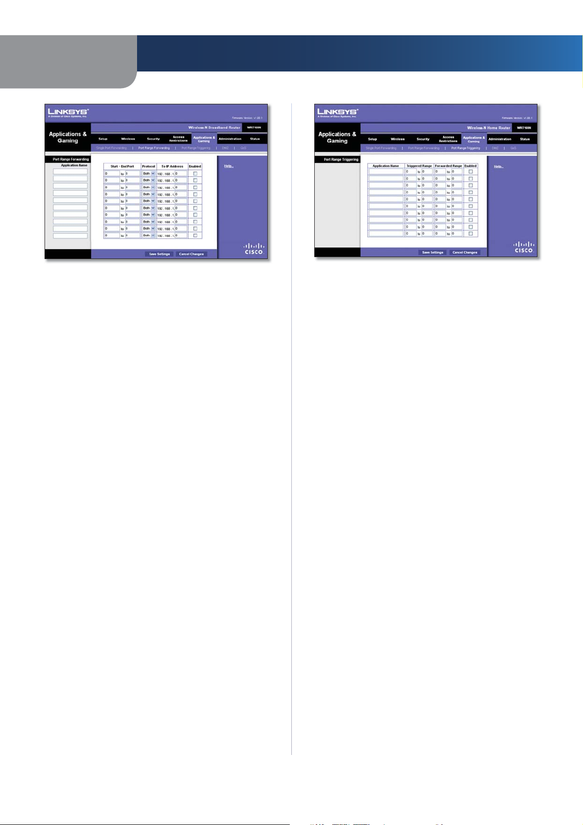
Applications and Gaming > Port Range
Forwarding
The Port Range Forwarding screen allows you to set up
public services on your network, such as web servers,
ftp servers, e-mail servers, or other specialized Internet
applications. (Specialized Internet applications are any
applications that use Internet access to perform functions
such as videoconferencing or online gaming. Some Internet
applications may not require any forwarding.)
When users send these types of requests to your network via
the Internet, the Router will forward those requests to the
appropriate servers (computers). Before using forwarding,
you should assign static IP addresses to the designated
servers (use the DHCP Reservation feature on the Basic Setup
screen).
If you need to forward all ports to one computer, click the
DMZ tab.
Applications and Gaming > Single Port Forwarding
Wireless-N Broadband Router
20
Page 23
Chapter 3
Advanced Configuration
Applications and Gaming > Port Range Forwarding
Port Range Forwarding
To forward a port, enter the information on each line for
the criteria required.
Application Name In this field, enter the name you
wish to give the application. Each name can be up to 12
characters.
Start~End Port Enter the number or range of port(s)
used by the server or Internet applications. Check
with the Internet application documentation for more
information.
Protocol Select the protocol used for this application,
either TCP or UDP, or Both.
To IP Address For each application, enter the IP address
of the PC running the specific application. If you assigned
a static IP address to the PC, then you can click DHCP
Reservation on the Basic Setup screen to look up its static
IP address.
Enabled Select Enabled to enable port forwarding for
the applications you have defined.
Click Save Settings to apply your changes, or click Cancel
Changes to cancel your changes.
Applications & Gaming > Port Range
Triggering
Applications and Gaming > Port Range Triggering
Port Range Triggering
Application Name Enter the application name of the
trigger.
Triggered Range For each application, enter the starting
and ending port numbers of the triggered port number
range. Check with the Internet application documentation
for the port number(s) needed.
Forwarded Range For each application, enter the starting
and ending port numbers of the forwarded port number
range. Check with the Internet application documentation
for the port number(s) needed.
Enabled Select Enabled to enable port triggering for the
applications you have defined.
Click Save Settings to apply your changes, or click Cancel
Changes to cancel your changes.
Applications and Gaming > DMZ
The DMZ feature allows one network computer to be
exposed to the Internet for use of a special-purpose
service such as Internet gaming or videoconferencing.
DMZ hosting forwards all the ports at the same time to
one PC. The Port Range Forwarding feature is more secure
because it only opens the ports you want to have opened,
while DMZ hosting opens all the ports of one computer,
exposing the computer to the Internet.
The Port Range Triggering screen allows the Router to
watch outgoing data for specific port numbers. The IP
address of the computer that sends the matching data is
remembered by the Router, so that when the requested
data returns through the Router, the data is pulled back
to the proper computer by way of IP address and port
mapping rules.
Wireless-N Broadband Router
21
Page 24
Chapter 3
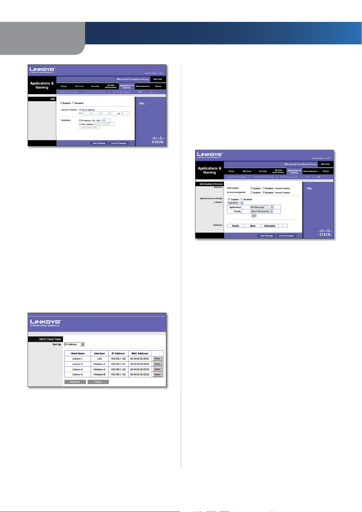
Applications and Gaming > DMZ
DMZ
Any PC whose port is being forwarded must have its DHCP
client function disabled and should have a new static IP
address assigned to it because its IP address may change
when using the DHCP function.
Enabled/Disabled To disable DMZ hosting, select
Disabled. To expose one PC, select Enabled. Then
configure the following settings:
Source IP Address If you want any IP address to be the
source, select Any IP Address. If you want to specify an IP
address or range of IP addresses as the designated source,
select and complete the IP address range fields.
Destination If you want to specify the DMZ host by IP
address, select IP Address and enter the IP address in
the field provided. If you want to specify the DMZ host
by MAC address, select MAC Address and enter the MAC
address in the field provided. To retrieve this information,
click DHCP Client Table.
Advanced Configuration
date information, click Refresh. To exit this screen and
return to the DMZ screen, click Close.
Click Save Settings to apply your changes, or click Cancel
Changes to cancel your changes.
Applications and Gaming > QoS
Quality of Service (QoS) ensures better service to
high-priority types of network traffic, which may
involve demanding, real-time applications, such as
videoconferencing.
Applications and Gaming > QoS
QoS (Quality of Service)
Wireless
You can configure the support and No Acknowledgement
settings in this section.
WMM Support If you have other devices that support Wi-
Fi Multimedia (WMM) on your network, keep the default,
Enabled. Otherwise, select Disabled.
No Acknowledgement If you want to disable the Router’s
Acknowledgement feature, so the Router will not re-send
data if an error occurs, then select Enabled. Otherwise,
keep the default, Disabled.
DMZ > DHCP Client Table
DHCP Client Table
The DHCP Client Table lists computers and other
devices that have been assigned IP addresses by the
Router. The list can be sorted by Client Name, Interface,
IP Address, MAC Address, and Expired Time (how
much time is left for the current IP address). To select
a DHCP client, click Select. To retrieve the most up-to-
Wireless-N Broadband Router
Internet Access Priority
In this section, you can set the bandwidth priority for a
variety of applications and devices. There are four levels
priority: High, Medium, Normal, or Low. When you set
priority, do not set all applications to High, because this will
defeat the purpose of allocating the available bandwidth.
If you want to select below normal bandwidth, select Low.
Depending on the application, a few attempts may be
needed to set the appropriate bandwidth priority.
Enabled/Disabled To use the QoS policies you have set,
keep the default, Enabled. Otherwise, select Disabled.
22
Page 25

Chapter 3
Advanced Configuration
Category
There are four categories available. Select one of the
following: Applications, Online Games, MAC Address,
Ethernet Port, or Voice Device. Proceed to the instructions
for your selection.
Applications
Applications Select the appropriate application. If you
select Add a New Application, follow the Add a New
Application instructions.
Priority Select the appropriate priority: High, Medium,
Normal, or Low.
Click Add to save your changes. Your new entry will appear
in the Summary list.
Add a New Application
Priority Select the appropriate priority: High, Medium
(Recommend), Normal, or Low.
Click Add to save your changes. Your new entry will appear
in the Summary list.
MAC Address
QoS > MAC Address
Enter a Name Enter a name for your device.
MAC Address Enter the MAC address of your device.
Priority Select the appropriate priority: High, Medium
(Recommend), Normal, or Low.
Click Add to save your changes. Your new entry will appear
in the Summary list.
Ethernet Port
QoS > Add a New Application
Enter a Name Enter any name to indicate the name of
the entry.
Port Range Enter the port range that the application will
be using. For example, if you want to allocate bandwidth
for FTP, you can enter 21-21. If you need services for an
application that uses from 1000 to 1250, you enter 10001250 as your settings. You can have up to three ranges
to define for this bandwidth allocation. Port numbers
can range from 1 to 65535. Check your application’s
documentation for details on the service ports used.
Select the protocol TCP or UDP, or select Both.
Priority Select the appropriate priority: High, Medium
(Recommend), Normal, or Low.
Click Add to save your changes. Your new entry will appear
in the Summary list.
Online Games
QoS > Online Games
Games Select the appropriate game.
QoS > Ethernet Port
Ethernet Select the appropriate Ethernet port.
Priority Select the appropriate priority: High, Medium
(Recommend), Normal, or Low.
Click Add to save your changes. Your new entry will appear
in the Summary list.
Voice Device
QoS > Voice Device
Enter a Name Enter a name for your voice device.
MAC Address Enter the MAC address of your voice
device.
Priority Select the appropriate priority: High
(Recommend), Medium, Normal, or Low.
Click Add to save your changes. Your new entry will appear
in the Summary list.
Wireless-N Broadband Router
23
Page 26

Chapter 3
Advanced Configuration
Summary
This lists the QoS entries you have created for your
applications and devices.
Priority This column displays the bandwidth priority of
High, Medium, Normal, or Low.
Name This column displays the application, device, or
port name.
Information This column displays the port range or
MAC address entered for your entry. If a pre-configured
application or game was selected, there will be no valid
entry shown in this section.
Remove Click this button to remove an entry.
Edit Click this button to make changes.
Click Save Settings to apply your changes, or click Cancel
Changes to cancel your changes.
Administration > Management
The Administration > Management screen allows the
network’s administrator to manage specific Router
functions for access and security.
Web Access
Web Utility Access HTTP (HyperText Transport Protocol)
is the communications protocol used to connect to servers
on the World Wide Web. HTTPS uses SSL (Secured Socket
Layer) to encrypt data transmitted for higher security.
Select HTTP or HTTPS. HTTP is the default.
Web Utility Access via Wireless If you are using the
Router in a public domain where you are giving wireless
access to your guests, you can disable wireless access to
the Router’s web-based utility. You will only be able to
access the utility via a wired connection if you disable
the setting. Keep the default, Enabled, to allow wireless
access to the utility, or select Disabled to block wireless
access to the utility.
Remote Access
Remote Management To permit remote access of the
Router, from outside the local network, select Enabled.
Otherwise, keep the default, Disabled.
Web Utility Access HTTP (HyperText Transport Protocol)
is the communications protocol used to connect to servers
on the World Wide Web. HTTPS uses SSL (Secured Socket
Layer) to encrypt data transmitted for higher security.
Select HTTP or HTTPS. HTTP is the default.
Remote Upgrade If you want to be able to upgrade the
Router remotely, from outside the local network, select
Enabled. (You must have the Remote Management
feature enabled as well.) Otherwise, keep the default,
Disabled.
Allowed Remote IP Address If you want to be able to
access the Router from any external IP address, select Any
IP Address. If you want to specify an external IP address or
range of IP addresses, then select the second option and
complete the fields provided.
Remote Management Port Enter the port number that
will be open to outside access.
Administration > Management
Management
Router Access
To ensure the Router’s security, you will be asked for your
password when you access the Router’s web-based utility.
The default is admin.
Router Password Enter a new password for the Router.
Re-enter to confirm Enter the password again to
confirm.
Wireless-N Broadband Router
NOTE: When you are in a remote location
and wish to manage the Router, enter
http://<Internet_IP_address>:port or
https://<Internet_IP_address>:port,
depending on whether you use HTTP or HTTPS.
Enter the Router’s specific Internet IP address in
place of <Internet_IP_address>, and enter the
Remote Management Port number in place of
the word port.
UPnP
Universal Plug and Play (UPnP) allows Windows Me and XP
to automatically configure the Router for various Internet
applications, such as gaming and videoconferencing.
24
Page 27

Chapter 3
UPnP If you want to use UPnP, keep the default setting,
Enabled. Otherwise, select Disabled.
Allow Users to Configure Keep the default, Enabled,
if you want to be able to make manual changes to the
Router while using the UPnP feature. Otherwise, select
Disabled.
Allow Users to Disable Internet Access Select Enabled,
if you want to be able to prohibit any and all Internet
connections. Otherwise, keep the default setting,
Disabled.
Advanced Configuration
Backup and Restore
Backup Configurations To back up the Router’s
configuration settings, click this button and follow the onscreen instructions.
Restore Configurations To restore the Router’s
configuration settings, click this button and follow the onscreen instructions. (You must have previously backed up
the Router’s configuration settings.)
Click Save Settings to apply your changes, or click Cancel
Changes to cancel your changes.
Administration > Log
The Router can keep logs of all traffic for your Internet
connection.
Log > View Log
Log
Typ e Select Incoming Log, Outgoing Log, Security
•
Log, or DHCP Client Log.
<Type> Log The Incoming Log will display a
•
temporary log of the source IP addresses and
destination port numbers for the incoming Internet
traffic. The Outgoing Log will display a temporary
log of the local IP addresses, destination URLs/IP
addresses, and service/port numbers for the outgoing
Internet traffic. The Security log will display the login
information for the web-based utility. The DHCP
Client Log will display the LAN DHCP server status
information.
Click Save the Log to save this information to a file
on your PC’s hard drive. Click Refresh to update the
log. Click Clear to clear all the information that is
displayed.
Click Save Settings to apply your changes, or click Cancel
Changes to cancel your changes.
Administration > Log
Log
Log To disable the Log function, select Disabled. To
monitor traffic between the network and the Internet,
keep the default, Enabled. With logging enabled, you can
choose to view temporary logs.
View Log To view the logs, click View Log.
Wireless-N Broadband Router
Administration > Diagnostics
The diagnostic tests (Ping and Traceroute) allow you to
check the connections of your network devices, including
connection to the Internet.
Administration > Diagnostics
25
Page 28

Chapter 3
Advanced Configuration
Diagnostics
Ping Test
The Ping test checks the status of a connection.
IP or URL Address Enter the address of the PC whose
connection you wish to test.
Packet Size Enter the packet size you want to use. The
default is 32 bytes.
Times to Ping Enter many times you wish to test it.
Start to Ping To run the test, click this button. The Ping
Test screen will show if the test was successful. Click Close
to return to the Diagnostics screen.
Diagnostics > Ping
Administration > Factory Defaults
The Administration > Factory Defaults screen allows you
to restore the Router’s configuration to its factory default
settings.
Administration > Factory Defaults
NOTE: Do not restore the factory defaults unless
you are having difficulties with the Router and
have exhausted all other troubleshooting
measures. Once the Router is reset, you will have
to re-enter all of your configuration settings.
Factory Defaults
Restore All Settings To reset the Router’s settings to the
default values, click this button and then follow the onscreen instructions. Any settings you have saved will be
lost when the default settings are restored.
Traceroute Test
The Traceroute test tests the performance of a
connection.
IP or URL Address Enter the address of the PC whose
connection you wish to test.
Start to Traceroute To run the test, click this button. The
Traceroute Test screen will show if the test was successful.
Click Close to return to the Diagnostics screen.
Diagnostics > Traceroute
Administration > Firmware Upgrade
The Firmware Upgrade screen allows you to upgrade the
Router’s firmware. Do not upgrade the firmware unless
you are experiencing problems with the Router or the new
firmware has a feature you want to use.
Administration > Firmware Upgrade
NOTE: The Router may lose the settings you
have customized. Before you upgrade its
firmware, write down all of your custom settings.
After you upgrade its firmware, you will have to
re-enter all of your configuration settings.
Wireless-N Broadband Router
26
Page 29

Chapter 3
Advanced Configuration
Firmware Upgrade
Before upgrading the firmware, download the Router’s
firmware upgrade file from the Linksys website,
www.linksys.com. Then extract the file.
Please select a file to upgrade the firmware Click
Browse and select the extracted firmware upgrade file.
Start to Upgrade After you have selected the
appropriate file, click this button, and f
instructions.
ollow the on-screen
Status > Router
The Router screen displays information about the Router
and its current settings.
Status > Local Network
The Local Network screen displays information about the
local, wired network.
Status > Local Network
Local Network
Local MAC Address The MAC address of the Router’s
local, wired interface is displayed here.
Router IP Address This shows the Router’s IP address, as
it appears on your local network.
Subnet Mask This shows the Subnet Mask of the Router.
Status > Router
Router Information
Firmware Version This is the version number of the
Router’s current firmware.
Current Time This shows the time set on the Router.
Internet MAC Address This is the Router’s MAC Address,
as seen by your ISP.
Host Name If required by your ISP, this was entered on
the Basic Setup screen.
Domain Name If required by your ISP, this was entered
on the Basic Setup screen.
Internet Connection
This section shows the current network information
stored in the Router. The information varies depending on
the Internet connection type selected on the Basic Setup
screen.
Click Refresh to update the on-screen information.
DHCP Server
DHCP Server The status of the Router’s DHCP server
function is displayed here.
Start IP Address For the range of IP addresses used by
devices on your local network, the starting IP address is
shown here.
End IP Address For the range of IP addresses used by
devices on your local network, the ending IP address is
shown here.
DHCP Clients Table Click this button to view a list of PCs
that are using the Router as a DHCP server.
DHCP Clients Table
Wireless-N Broadband Router
27
Page 30

Chapter 3
DHCP Client Table
The DHCP Client Table lists computers and other
devices that have been assigned IP addresses by the
Router. The list can be sorted by Client Name, Interface,
IP Address, MAC Address, and Expired Time (how
much time is left for the current IP address). To remove
a DHCP client, click Delete. To retrieve the most up-todate information, click Refresh. To exit this screen and
return to the Local Network screen, click Close.
Status > Wireless Network
The Wireless Network screen displays information about
your wireless network.
Advanced Configuration
Status > Wireless
Wireless Network
MAC Address The MAC address of the Router’s local,
wireless interface is displayed here.
Mode Displayed here is the wireless mode used by the
network.
Network Name (SSID) Displayed here is the name of the
wireless network, which is also called the SSID.
Radio Band Shown here is the Radio Band setting
selected on the Basic Wireless Settings screen.
Wide Channel Shown here is the Wide Channel setting
selected on the Basic Wireless Settings screen.
Standard Channel Shown here is the Standard Channel
setting selected on the Basic Wireless Settings screen.
Security Displayed here is the wireless security method
used by the Router.
SSID Broadcast Displayed here is the status of the SSID
Broadcast feature.
Wireless-N Broadband Router
28
Page 31

Appendix A
Troubleshooting
Appendix A:
Troubleshooting
Your computer cannot connect to the Internet.
Follow these instructions until your computer can connect
to the Internet:
•
Make sure that the Router is powered on. The Power
LED should be green and not flashing.
•
If the Power LED is flashing, then power off all of
your network devices, including the modem, Router,
and computers. Then power on each device in the
following order:
1.
Cable or DSL modem
2.
Router
3.
Computer
•
Check the cable connections. The computer should
be connected to one of the ports numbered 1-4 on
the Router, and the modem must be connected to the
Internet port on the Router.
The modem does not have an Ethernet port.
The modem is a dial-up modem for traditional dial-up
service. To use the Router, you need a cable/DSL modem
and high-speed Internet connection.
You cannot use the DSL service to connect manually to
the Internet.
After you have installed the Router, it will automatically
connect to your Internet Service Provider (ISP), so you no
longer need to connect manually.
When you double-click the web browser, you are
prompted for a username and password. If you want to
get rid of the prompt, follow these instructions.
Launch the web browser and perform the following steps
(these steps are specific to Internet Explorer but are similar
for other browsers):
1.
Select Tools > Internet Options.
2.
Click the Connections tab.
3.
Select Never dial a connection.
4.
Click OK.
The Router does not have a coaxial port for the cable
connection.
The Router does not replace your modem. You still need
your cable modem in order to use the Router. Connect
your cable connection to the cable modem, and then
insert the setup CD into your computer. Click Setup and
follow the on-screen instructions.
The computer cannot connect wirelessly to the network.
Make sure the wireless network name or SSID is the same
on both the computer and the Router. If you have enabled
wireless security, then make sure the same security
method and key are used by both the computer and the
Router.
You need to modify the settings on the Router.
Open the web browser (for example, Internet Explorer or
Firefox), and enter the Router’s IP address in the address
field (the default IP address is 192.168.1.1). When
prompted, enter the password to the Router (the default is
admin). Click the appropriate tab to change the settings.
The DSL telephone line does not t into the Router’s
Internet port.
The Router does not replace your modem. You still need
your DSL modem in order to use the Router. Connect the
telephone line to the DSL modem, and then insert the
setup CD into your computer. Click Setup and follow the
on-screen instructions.
Wireless-N Broadband Router
WEB: If your questions are not addressed here,
refer to the Linksys website, www.linksys.com
29
Page 32

Appendix B
Appendix B:
Specifications
Model WRT160N
Standards Draft 802.11n, 802.11g, 802.11b,
802.3, 802.3u
Ports Power, Internet, and Ethernet
Buttons Reset, Wi-Fi Protected Setup
LEDs Ethernet (1-4), Wi-Fi Protected
Setup, Wireless, Internet, Power
Cabling Type CAT 5e
RF Power
RF Pwr (EIRP) in dBm 17 dBm
Antenna Gain in dBi 1.5 dBi
UPnP able/cert Able
Security Features WEP, WPA, WPA2
Security Key Bits 128-Bit, 256-Bit
28dBm
Specifications
Environmental
Dimensions 7.95" x 6.3" x 1.34"
(202 x 160 x 34 mm)
Weight 13.40 oz (0.38 kg)
Power 12V, 1A
Certication FCC, CE, IC-03, Wi-Fi
Operating Temp. 0 to 40°C (32 to 104°F)
Storage Temp. -20 to 60°C (-4 to 140°F)
Operating Humidity 10 to 85% Noncondensing
Storage Humidity 5 to 90% Noncondensing
Specications are subject to change without notice.
0.5A
Wireless-N Broadband Router
30
Page 33

Appendix C
Warranty Information
Appendix C:
Warranty Information
Limited Warranty
Linksys warrants this Linksys hardware product against
defects in materials and workmanship under normal
use for the Warranty Period, which begins on the date of
purchase by the original end-user purchaser and lasts for
the period specified below:
•
One (1) year for new product
•
Ninety (90) days for refurbished product
This limited warranty is non-transferable and extends only
to the original end-user purchaser. Your exclusive remedy
and Linksys’ entire liability under this limited warranty
will be for Linksys, at its option, to (a) repair the product
with new or refurbished parts, (b) replace the product
with a reasonably available equivalent new or refurbished
Linksys product, or (c) refund the purchase price of the
product less any rebates. Any repaired or replacement
products will be warranted for the remainder of the
original Warranty Period or thirty (30) days, whichever is
longer. All products and parts that are replaced become
the property of Linksys.
Exclusions and Limitations
This limited warranty does not apply if: (a) the product
assembly seal has been removed or damaged, (b) the
product has been altered or modified, except by Linksys, (c)
the product damage was caused by use with non-Linksys
products, (d) the product has not been installed, operated,
repaired, or maintained in accordance with instructions
supplied by Linksys, (e) the product has been subjected to
abnormal physical or electrical stress, misuse, negligence,
or accident, (f) the serial number on the Product has been
altered, defaced, or removed, or (g) the product is supplied
or licensed for beta, evaluation, testing or demonstration
purposes for which Linksys does not charge a purchase
price or license fee.
ALL SOFTWARE PROVIDED BY LINKSYS WITH THE
PRODUCT, WHETHER FACTORY LOADED ON THE
PRODUCT OR CONTAINED ON MEDIA ACCOMPANYING
THE PRODUCT, IS PROVIDED “AS IS” WITHOUT WARRANTY
OF ANY KIND. Without limiting the foregoing, Linksys does
not warrant that the operation of the product or software
will be uninterrupted or error free. Also, due to the
continual development of new techniques for intruding
upon and attacking networks, Linksys does not warrant
that the product, software or any equipment, system or
network on which the product or software is used will be
free of vulnerability to intrusion or attack. The product
may include or be bundled with third party software or
service offerings. This limited warranty shall not apply to
such third party software or service offerings. This limited
warranty does not guarantee any continued availability
of a third party’s service for which this product’s use or
operation may require.
TO THE EXTENT NOT PROHIBITED BY LAW, ALL IMPLIED
WARRANTIES AND CONDITIONS OF MERCHANTABILITY,
SATISFACTORY QUALITY OR FITNESS FOR A PARTICULAR
PURPOSE ARE LIMITED TO THE DURATION OF THE
WARRANTY PERIOD. ALL OTHER EXPRESS OR IMPLIED
CONDITIONS, REPRESENTATIONS AND WARRANTIES,
INCLUDING, BUT NOT LIMITED TO, ANY IMPLIED
WARRANTY OF NON-INFRINGEMENT, ARE DISCLAIMED.
Some jurisdictions do not allow limitations on how long
an implied warranty lasts, so the above limitation may not
apply to you. This limited warranty gives you specific legal
rights, and you may also have other rights which vary by
jurisdiction.
TO THE EXTENT NOT PROHIBITED BY LAW, IN NO EVENT
WILL LINKSYS BE LIABLE FOR ANY LOST DATA, REVENUE
OR PROFIT, OR FOR SPECIAL, INDIRECT, CONSEQUENTIAL,
INCIDENTAL OR PUNITIVE DAMAGES, REGARDLESS OF THE
THEORY OF LIABILITY (INCLUDING NEGLIGENCE), ARISING
OUT OF OR RELATED TO THE USE OF OR INABILITY TO
USE THE PRODUCT (INCLUDING ANY SOFTWARE), EVEN
IF LINKSYS HAS BEEN ADVISED OF THE POSSIBILITY OF
SUCH DAMAGES. IN NO EVENT WILL LINKSYS’ LIABILITY
EXCEED THE AMOUNT PAID BY YOU FOR THE PRODUCT.
The foregoing limitations will apply even if any warranty
or remedy provided under this limited warranty fails of
its essential purpose. Some jurisdictions do not allow
the exclusion or limitation of incidental or consequential
damages, so the above limitation or exclusion may not
apply to you.
Obtaining Warranty Service
If you have a question about your product or experience a
problem with it, please go to www.linksys.com/support
where you will find a variety of online support tools and
information to assist you with your product. If the product
proves defective during the Warranty Period, contact
Linksys Technical Support for instructions on how to
obtain warranty service. The telephone number for Linksys
Technical Support in your area can be found in the product
User Guide and at www.linksys.com. Have your product
serial number and proof of purchase on hand when calling.
A DATED PROOF OF ORIGINAL PURCHASE IS REQUIRED
TO PROCESS WARRANTY CLAIMS. If you are requested to
return your product, you will be given a Return Materials
Authorization (RMA) number. You are responsible for
properly packaging and shipping your product to Linksys
at your cost and risk. You must include the RMA number
and a copy of your dated proof of original purchase when
returning your product. Products received without a RMA
number and dated proof of original purchase will be
Wireless-N Broadband Router
31
Page 34

Appendix C
rejected. Do not include any other items with the product
you are returning to Linksys. Defective product covered
by this limited warranty will be repaired or replaced and
returned to you without charge. Customers outside of
the United States of America and Canada are responsible
for all shipping and handling charges, custom duties,
VAT and other associated taxes and charges. Repairs or
replacements not covered under this limited warranty will
be subject to charge at Linksys’ then-current rates.
Technical Support
This limited warranty is neither a service nor a support
contract. Information about Linksys’ current technical
support offerings and policies (including any fees for
support services) can be found at:
www.linksys.com/support.
This limited warranty is governed by the laws of the
jurisdiction in which the Product was purchased by you.
Please direct all inquiries to: Linksys, P.O. Box 18558, Irvine,
CA 92623.
Warranty Information
Wireless-N Broadband Router
32
Page 35

Appendix D
Regulatory Information
Appendix D:
Regulatory Information
FCC Statement
This device complies with Part 15 of the FCC Rules.
Operation is subject to the following two conditions: (1)
This device may not cause harmful interference, and (2) this
device must accept any interference received, including
interference that may cause undesired operation.
This product has been tested and complies with the
specifications for a Class B digital device, pursuant to Part
15 of the FCC Rules. These limits are designed to provide
reasonable protection against harmful interference in
a residential installation. This equipment generates,
uses, and can radiate radio frequency energy and, if not
installed and used according to the instructions, may
cause harmful interference to radio communications.
However, there is no guarantee that interference will not
occur in a particular installation. If this equipment does
cause harmful interference to radio or television reception,
which is found by turning the equipment off and on, the
user is encouraged to try to correct the interference by
one or more of the following measures:
•
Reorient or relocate the receiving antenna
•
Increase the separation between the equipment or
devices
•
Connect the equipment to an outlet other than the
receiver’s
•
Consult a dealer or an experienced radio/TV technician
for assistance
FCC Caution: Any changes or modifications not expressly
approved by the party responsible for compliance could
void the user’s authority to operate this equipment.
FCC Radiation Exposure Statement
This equipment complies with FCC radiation exposure
limits set forth for an uncontrolled environment. This
equipment should be installed and operated with
minimum distance 20cm between the radiator and your
body.
This transmitter must not be co-located or operating in
conjunction with any other antenna or transmitter. IEEE
802.11b or 802.11g operation of this product in the USA is
firmware-limited to channels 1 through 11.
Safety Notices
Caution: To reduce the risk of fire, use only No.26 AWG
•
or larger telecommunication line cord.
Do not use this product near water, for example, in a
•
wet basement or near a swimming pool.
Avoid using this product during an electrical storm.
•
There may be a remote risk of electric shock from
lightning.
WARNING: This product contains lead, known
to the State of California to cause cancer, and
birth defects or other reproductive harm. Wash
hands after handling.
Industry Canada Statement
This Class B digital apparatus complies with Canadian
ICES-003 and RSS210.
Operation is subject to the following two conditions:
1.
This device may not cause interference and
2.
This device must accept any interference, including
interference that may cause undesired operation of the
device. This device has been designed to operate with
an antenna having a maximum gain of 2dBi. Antenna
having a higher gain is strictly prohibited per regulations
of Industry Canada. The required antenna impedance
is 50 ohms.
To reduce potential radio interference to other users,
the antenna type and its gain should be so chosen
that the EIRP is not more than required for successful
communication.
Industry Canada Radiation Exposure Statement:
This equipment complies with IC radiation exposure limits
set forth for an uncontrolled environment. This equipment
should be installed and operated with minimum distance
20cm between the radiator & your body.
This transmitter must not be co-located or operating in
conjunction with any other antenna or transmitter.
1.5dBi.
Wireless-N Broadband Router
33
Page 36

Appendix D
Regulatory Information
Avis d’Industrie Canada
Cet appareil numérique de la classe B est conforme aux
normes NMB-003 et RSS210 du Canada.
L’utilisation de ce dispositif est autorisée seulement aux
conditions suivantes :
1.
il ne doit pas produire de brouillage et
2.
il doit accepter tout brouillage radioélectrique reçu,
même si ce brouillage est susceptible de compromettre
le fonctionnement du dispositif. Le dispositif a été
conçu pour fonctionner avec une antenne ayant un gain
maximum de 2 dBi. Les règlements d’Industrie Canada
interdisent strictement l’utilisation d’antennes dont le
gain est supérieur à cette limite. L’impédance requise
de l’antenne est de 50 ohms.
Afin de réduire le risque d’interférence aux autres
utilisateurs, le type d’antenne et son gain doivent
être choisis de façon à ce que la puissance isotrope
rayonnée équivalente (p.i.r.e.) ne soit pas supérieure
au niveau requis pour obtenir une communication
satisfaisante.
Avis d’Industrie Canada concernant l’exposition
aux radiofréquences :
Avis de non-responsabilité concernant les
appareils sans fil
Les performances maximales pour les réseaux sans fil
sont tirées des spécifications de la norme IEEE 802.11.
Les performances réelles peuvent varier, notamment
en fonction de la capacité du réseau sans fil, du débit
de la transmission de données, de la portée et de la
couverture. Les performances dépendent de facteurs,
conditions et variables multiples, en particulier de la
distance par rapport au point d’accès, du volume du trafic
réseau, des matériaux utilisés dans le bâtiment et du
type de construction, du système d’exploitation et de la
combinaison de produits sans fil utilisés, des interférences
et de toute autre condition défavorable.
Ce matériel est conforme aux limites établies par IC
en matière d’exposition aux radiofréquences dans un
environnement non contrôlé. Ce matériel doit être installé
et utilisé à une distance d’au moins 20 cm entre l’antenne
et le corps de l’utilisateur.
L’émetteur ne doit pas être placé près d’une autre antenne
ou d’un autre émetteur, ou fonctionner avec une autre
antenne ou un autre émetteur.
Wireless Disclaimer
The maximum performance for wireless is derived from
IEEE Standard 802.11 specifications. Actual performance
can vary, including lower wireless network capacity,
data throughput rate, range and coverage. Performance
depends on many factors, conditions and variables,
including distance from the access point, volume of
network traffic, building materials and construction,
operating system used, mix of wireless products used,
interference and other adverse conditions.
Wireless-N Broadband Router
34
Page 37

Appendix D
Regulatory Information
User Information for Consumer Products
Covered by EU Directive 2002/96/EC on
Waste Electric and Electronic Equipment
(WEEE)
This document contains important information for users
with regards to the proper disposal and recycling of
Linksys products. Consumers are required to comply with
this notice for all electronic products bearing the following
symbol:
English - Environmental Information for Customers in
the European Union
European Directive 2002/96/EC requires that the equipment
bearing this symbol
not be disposed of with unsorted municipal waste. The symbol
indicates that this product should be disposed of separately
from regular household waste streams. It is your responsibility to
dispose of this and other electric and electronic equipment via
designated collection facilities appointed by the government or
local authorities. Correct disposal and recycling will help prevent
potential negative consequences to the environment and
human health. For more detailed information about the disposal
of your old equipment, please contact your local authorities,
waste disposal service, or the shop where you purchased the
product.
Български (Bulgarian) - Информация относно
опазването на околната среда за потребители в
Европейския съюз
Европейска директива 2002/96/EC изисква уредите, носещи
този символ
се изхвърля т с несортирани битови отпадъци. Символът
обозначава, че изделието трябва да се изхвърля отделно от
сметосъбирането на обикновените битови отпадъци. Ваша
е отговорността този и другите електрически и електронни
уреди да се изхвърлят в предварително определени от
държавните или общински органи специализирани пунктове
за събиране. Правилното изхвърляне и рециклиране
ще спомогнат да се предотвратят евентуални вредни за
околната среда и здравето на населението последствия. За
по-подробна информация относно изхвърлянето на вашите
стари уреди се обърнете към местните власти, службите за
сметосъбиране или магазина, от който сте закупили уреда.
on the product and/or its packaging must
върху изделието и/или опаковката му, да не
Ceština (Czech) - Informace o ochraně životního
prostředí pro zákazníky v zemích Evropské unie
Evropská směrnice 2002/96/ES zakazuje, aby zařízení označené
tímto symbolem
s netříděným komunálním odpadem. Tento symbol udává,
že daný produkt musí být likvidován odděleně od běžného
komunálního odpadu. Odpovídáte za likvidaci tohoto produktu
a dalších elektrických a elektronických zařízení prostřednictvím
určených sběrných míst stanovených vládou nebo místními
úřady. Správná likvidace a recyklace pomáhá předcházet
potenciálním negativním dopadům na životní prostředí a lidské
zdraví. Podrobnější informace o likvidaci starého vybavení si
laskavě vyžádejte od místních úřadů, podniku zabývajícího se
likvidací komunálních odpadů nebo obchodu, kde jste produkt
zakoupili.
na produktu anebo na obalu bylo likvidováno
Dansk (Danish) - Miljøinformation for kunder i EU
EU-direktiv 2002/96/EF kræver, at udstyr der bærer dette symbol
på produktet og/eller emballagen ikke må bortskaffes som
usorteret kommunalt affald. Symbolet betyder, at dette produkt
skal bortskaffes adskilt fra det almindelige husholdningsaffald.
Det er dit ansvar at bortskaffe dette og andet elektrisk og
elektronisk udstyr via bestemte indsamlingssteder udpeget
af staten eller de lokale myndigheder. Korrekt bortskaffelse
og genvinding vil hjælpe med til at undgå mulige skader for
miljøet og menneskers sundhed. Kontakt venligst de lokale
myndigheder, renovationstjenesten eller den butik, hvor du
har købt produktet, angående mere detaljeret information om
bortskaffelse af dit gamle udstyr.
Deutsch (German) - Umweltinformation für Kunden
innerhalb der Europäischen Union
Die Europäische Richtlinie 2002/96/EC verlangt, dass technische
Ausrüstung, die direkt am Gerät und/oder an der Verpackung mit
diesem Symbol versehen ist
Gemeindeabfall entsorgt werden darf. Das Symbol weist darauf
hin, dass das Produkt von regulärem Haushaltmüll getrennt
entsorgt werden sollte. Es liegt in Ihrer Verantwortung, dieses
Gerät und andere elektrische und elektronische Geräte über
die dafür zuständigen und von der Regierung oder örtlichen
Behörden dazu bestimmten Sammelstellen zu entsorgen.
Ordnungsgemäßes Entsorgen und Recyceln trägt dazu bei,
potentielle negative Folgen für Umwelt und die menschliche
Gesundheit zu vermeiden. Wenn Sie weitere Informationen zur
Entsorgung Ihrer Altgeräte benötigen, wenden Sie sich bitte an
die örtlichen Behörden oder städtischen Entsorgungsdienste
oder an den Händler, bei dem Sie das Produkt erworben haben.
, nicht zusammen mit unsortiertem
Wireless-N Broadband Router
35
Page 38

Appendix D
Regulatory Information
Eesti (Estonian) - Keskkonnaalane informatsioon
Euroopa Liidus asuvatele klientidele
Euroopa Liidu direktiivi 2002/96/EÜ nõuete kohaselt on
seadmeid, millel on tootel või pakendil käesolev sümbol
keelatud kõrvaldada koos sorteerimata olmejäätmetega. See
sümbol näitab, et toode tuleks kõrvaldada eraldi tavalistest
olmejäätmevoogudest. Olete kohustatud kõrvaldama käesoleva
ja ka muud elektri- ja elektroonikaseadmed riigi või kohalike
ametiasutuste poolt ette nähtud kogumispunktide kaudu.
Seadmete korrektne kõrvaldamine ja ringlussevõtt aitab vältida
võimalikke negatiivseid tagajärgi keskkonnale ning inimeste
tervisele. Vanade seadmete kõrvaldamise kohta täpsema
informatsiooni saamiseks võtke palun ühendust kohalike
ametiasutustega, jäätmekäitlusfirmaga või kauplusega, kust te
toote ostsite.
,
Español (Spanish) - Información medioambiental para
clientes de la Unión Europea
La Directiva 2002/96/CE de la UE exige que los equipos que
lleven este símbolo
no deben eliminarse junto con otros residuos urbanos no
seleccionados. El símbolo indica que el producto en cuestión
debe separarse de los residuos domésticos convencionales con
vistas a su eliminación. Es responsabilidad suya desechar este y
cualesquiera otros aparatos eléctricos y electrónicos a través de
los puntos de recogida que ponen a su disposición el gobierno y
las autoridades locales. Al desechar y reciclar correctamente estos
aparatos estará contribuyendo a evitar posibles consecuencias
negativas para el medio ambiente y la salud de las personas. Si
desea obtener información más detallada sobre la eliminación
segura de su aparato usado, consulte a las autoridades locales,
al servicio de recogida y eliminación de residuos de su zona o
pregunte en la tienda donde adquirió el producto.
en el propio aparato y/o en su embalaje
ξλληνικά (Greek) - Στοιχεία περιβαλλοντικής
προστασίας για πελάτες εντός της Ευρωπαϊκής
Ένωσης
Η Κοινοτική Οδηγία 2002/96/EC απαιτεί ότι ο εξοπλισμός ο οποίος
φέρει αυτό το σύμβολο
του δεν πρέπει να απορρίπτεται μαζί με τα μικτά κοινοτικά
απορρίμματα. Το σύμβολο υποδεικνύει ότι αυτό το προϊόν θα
πρέπει να απορρίπτεται ξεχωριστά από τα συνήθη οικιακά
απορρίμματα. Είστε υπεύθυνος για την απόρριψη του παρόντος
και άλλου ηλεκτρικού και ηλεκτρονικού εξοπλισμού μέσω των
καθορισμένων εγκαταστάσεων συγκέντρωσης απορριμμάτων οι
οποίες παρέχονται από το κράτος ή τις αρμόδιες τοπικές αρχές.
Η σωστή απόρριψη και ανακύκλωση συμβάλλει στην πρόληψη
πιθανών αρνητικών συνεπειών για το περιβάλλον και την υγεία.
Για περισσότερες πληροφορίες σχετικά με την απόρριψη του
παλιού σας εξοπλισμού, παρακαλώ επικοινωνήστε με τις τοπικές
αρχές, τις υπηρεσίες απόρριψης ή το κατάστημα από το οποίο
αγοράσατε το προϊόν.
στο προϊόν και/ή στη συσκευασία
Français (French) - Informations environnementales
pour les clients de l’Union européenne
La directive européenne 2002/96/CE exige que l’équipement
sur lequel est apposé ce symbole
emballage ne soit pas jeté avec les autres ordures ménagères. Ce
symbole indique que le produit doit être éliminé dans un circuit
distinct de celui pour les déchets des ménages. Il est de votre
responsabilité de jeter ce matériel ainsi que tout autre matériel
électrique ou électronique par les moyens de collecte indiqués
par le gouvernement et les pouvoirs publics des collectivités
territoriales. L’élimination et le recyclage en bonne et due forme
ont pour but de lutter contre l’impact néfaste potentiel de ce
type de produits sur l’environnement et la santé publique. Pour
plus d’informations sur le mode d’élimination de votre ancien
équipement, veuillez prendre contact avec les pouvoirs publics
locaux, le service de traitement des déchets, ou l’endroit où vous
avez acheté le produit.
sur le produit et/ou son
Italiano (Italian) - Informazioni relative all’ambiente
per i clienti residenti nell’Unione Europea
La direttiva europea 2002/96/EC richiede che le apparecchiature
contrassegnate con questo simbolo
sull’imballaggio non siano smaltite insieme ai rifiuti urbani
non differenziati. Il simbolo indica che questo prodotto non
deve essere smaltito insieme ai normali rifiuti domestici. È
responsabilità del proprietario smaltire sia questi prodotti sia
le altre apparecchiature elettriche ed elettroniche mediante
le specifiche strutture di raccolta indicate dal governo o dagli
enti pubblici locali. Il corretto smaltimento ed il riciclaggio
aiuteranno a prevenire conseguenze potenzialmente negative
per l’ambiente e per la salute dell’essere umano. Per ricevere
informazioni più dettagliate circa lo smaltimento delle vecchie
apparecchiature in Vostro possesso, Vi invitiamo a contattare gli
enti pubblici di competenza, il servizio di smaltimento rifiuti o il
negozio nel quale avete acquistato il prodotto.
sul prodotto e/o
Latviešu valoda (Latvian) - Ekoloģiska informācija
klientiem Eiropas Savienības jurisdikcijā
Direktīvā 2002/96/EK ir prasība, ka aprīkojumu, kam pievienota
zīme
uz paša izstrādājuma vai uz tā iesaiņojuma, nedrīkst
izmest nešķirotā veidā kopā ar komunālajiem atkritumiem
(tiem, ko rada vietēji iedzīvotāji un uzņēmumi). Šī zīme nozīmē
to, ka šī ierīce ir jāizmet atkritumos tā, lai tā nenonāktu kopā ar
parastiem mājsaimniecības atkritumiem. Jūsu pienākums ir šo
un citas elektriskas un elektroniskas ierīces izmest atkritumos,
izmantojot īpašus atkritumu savākšanas veidus un līdzekļus, ko
nodrošina valsts un pašvaldību iestādes. Ja izmešana atkritumos
un pārstrāde tiek veikta pareizi, tad mazinās iespējamais
kaitējums dabai un cilvēku veselībai. Sīkākas ziņas par
novecojuša aprīkojuma izmešanu atkritumos jūs varat saņemt
vietējā pašvaldībā, atkritumu savākšanas dienestā, kā arī veikalā,
kur iegādājāties šo izstrādājumu.
Wireless-N Broadband Router
36
Page 39

Appendix D
Regulatory Information
Lietuvškai (Lithuanian) - Aplinkosaugos informacija,
skirta Europos Sąjungos vartotojams
Europos direktyva 2002/96/EC numato, kad įrangos, kuri ir
kurios pakuotė yra pažymėta šiuo simboliu (įveskite simbolį),
negalima šalinti kartu su nerūšiuotomis komunalinėmis
atliekomis. Šis simbolis rodo, kad gaminį reikia šalinti atskirai
nuo bendro buitinių atliekų srauto. Jūs privalote užtikrinti, kad
ši ir kita elektros ar elektroninė įranga būtų šalinama per tam
tikras nacionalinės ar vietinės valdžios nustatytas atliekų rinkimo
sistemas. Tinkamai šalinant ir perdirbant atliekas, bus išvengta
galimos žalos aplinkai ir žmonių sveikatai. Daugiau informacijos
apie jūsų senos įrangos šalinimą gali pateikti vietinės valdžios
institucijos, atliekų šalinimo tarnybos arba parduotuvės, kuriose
įsigijote tą gaminį.
Malti (Maltese) - Informazzjoni Ambjentali għal Klijenti
fl-Unjoni Ewropea
Id-Direttiva Ewropea 2002/96/KE titlob li t-tagħmir li jkun fih issimbolu
ma’ skart muniċipali li ma ġiex isseparat. Is-simbolu jindika
li dan il-prodott għandu jintrema separatament minn ma’ liskart domestiku regolari. Hija responsabbiltà tiegħek li tarmi
dan it-tagħmir u kull tagħmir ieħor ta’ l-elettriku u elettroniku
permezz ta’ faċilitajiet ta’ ġbir appuntati apposta mill-gvern jew
mill-awtoritajiet lokali. Ir-rimi b’mod korrett u r-riċiklaġġ jgħin
jipprevjeni konsegwenzi negattivi potenzjali għall-ambjent u
għas-saħħa tal-bniedem. Għal aktar informazzjoni dettaljata
dwar ir-rimi tat-tagħmir antik tiegħek, jekk jogħġbok ikkuntattja
lill-awtoritajiet lokali tiegħek, is-servizzi għar-rimi ta’ l-iskart, jew
il-ħanut minn fejn xtrajt il-prodott.
fuq il-prodott u/jew fuq l-ippakkjar ma jistax jintrema
Nederlands (Dutch) - Milieu-informatie voor klanten
in de Europese Unie
De Europese Richtlijn 2002/96/EC schrijft voor dat apparatuur die
is voorzien van dit symbool
niet mag worden ingezameld met niet-gescheiden huishoudelijk
afval. Dit symbool geeft aan dat het product apart moet worden
ingezameld. U bent zelf verantwoordelijk voor de vernietiging
van deze en andere elektrische en elektronische apparatuur via de
daarvoor door de landelijke of plaatselijke overheid aangewezen
inzamelingskanalen. De juiste vernietiging en recycling van
deze apparatuur voorkomt mogelijke negatieve gevolgen voor
het milieu en de gezondheid. Voor meer informatie over het
vernietigen van uw oude apparatuur neemt u contact op met
de plaatselijke autoriteiten of afvalverwerkingsdienst, of met de
winkel waar u het product hebt aangeschaft.
op het product of de verpakking,
Norsk (Norwegian) - Miljøinformasjon for kunder i EU
EU-direktiv 2002/96/EF krever at utstyr med følgende symbol
avbildet på produktet og/eller pakningen, ikke må kastes
sammen med usortert avfall. Symbolet indikerer at dette
produktet skal håndteres atskilt fra ordinær avfallsinnsamling
for husholdningsavfall. Det er ditt ansvar å kvitte deg med
dette produktet og annet elektrisk og elektronisk avfall via egne
innsamlingsordninger slik myndighetene eller kommunene
bestemmer. Korrekt avfallshåndtering og gjenvinning vil
være med på å forhindre mulige negative konsekvenser for
miljø og helse. For nærmere informasjon om håndtering av
det kasserte utstyret ditt, kan du ta kontakt med kommunen,
en innsamlingsstasjon for avfall eller butikken der du kjøpte
produktet.
Magyar (Hungarian) - Környezetvédelmi információ az
európai uniós vásárlók számára
A 2002/96/EC számú európai uniós irányelv megkívánja, hogy
azokat a termékeket, amelyeken, és/vagy amelyek csomagolásán
az alábbi címke
hulladékkal együtt kidobni. A címke azt jelöli, hogy az adott
termék kidobásakor a szokványos háztartási hulladékelszállítási
rendszerektõl elkülönített eljárást kell alkalmazni. Az Ön
felelõssége, hogy ezt, és más elektromos és elektronikus
berendezéseit a kormányzati vagy a helyi hatóságok által
kijelölt gyűjtõredszereken keresztül számolja fel. A megfelelõ
hulladékfeldolgozás segít a környezetre és az emberi egészségre
potenciálisan ártalmas negatív hatások megelõzésében. Ha
elavult berendezéseinek felszámolásához további részletes
információra van szüksége, kérjük, lépjen kapcsolatba a helyi
hatóságokkal, a hulladékfeldolgozási szolgálattal, vagy azzal
üzlettel, ahol a terméket vásárolta.
megjelenik, tilos a többi szelektálatlan lakossági
Polski (Polish) - Informacja dla klientów w Unii
Europejskiej o przepisach dotyczących ochrony
środowiska
Dyrektywa Europejska 2002/96/EC wymaga, aby sprzęt
oznaczony symbolem
opakowaniu nie był wyrzucany razem z innymi niesortowanymi
odpadami komunalnymi. Symbol ten wskazuje, że produkt
nie powinien być usuwany razem ze zwykłymi odpadami z
gospodarstw domowych. Na Państwu spoczywa obowiązek
wyrzucania tego i innych urządzeń elektrycznych oraz
elektronicznych w punktach odbioru wyznaczonych przez władze
krajowe lub lokalne. Pozbywanie się sprzętu we właściwy sposób
i jego recykling pomogą zapobiec potencjalnie negatywnym
konsekwencjom dla środowiska i zdrowia ludzkiego. W celu
uzyskania szczegółowych informacji o usuwaniu starego sprzętu,
prosimy zwrócić się do lokalnych władz, służb oczyszczania
miasta lub sklepu, w którym produkt został nabyty.
znajdującym się na produkcie i/lub jego
Wireless-N Broadband Router
37
Page 40

Appendix D
Regulatory Information
Português (Portuguese) - Informação ambiental para
clientes da União Europeia
A Directiva Europeia 2002/96/CE exige que o equipamento
que exibe este símbolo
não seja eliminado junto com os resíduos municipais não
separados. O símbolo indica que este produto deve ser
eliminado separadamente dos resíduos domésticos regulares.
É da sua responsabilidade eliminar este e qualquer outro
equipamento eléctrico e electrónico através das instalações
de recolha designadas pelas autoridades governamentais ou
locais. A eliminação e reciclagem correctas ajudarão a prevenir
as consequências negativas para o ambiente e para a saúde
humana. Para obter informações mais detalhadas sobre a
forma de eliminar o seu equipamento antigo, contacte as
autoridades locais, os serviços de eliminação de resíduos ou o
estabelecimento comercial onde adquiriu o produto.
no produto e/ou na sua embalagem
Română (Romanian) - Informaţii de mediu pentru
clienţii din Uniunea Europeană
Directiva europeană 2002/96/CE impune ca echipamentele care
prezintă acest simbol
nu fie casate împreună cu gunoiul menajer municipal. Simbolul
indică faptul că acest produs trebuie să fie casat separat de
gunoiul menajer obişnuit. Este responsabilitatea dvs. să casaţi
acest produs şi alte echipamente electrice şi electronice prin
intermediul unităţilor de colectare special desemnate de guvern
sau de autorităţile locale. Casarea şi reciclarea corecte vor ajuta
la prevenirea potenţialelor consecinţe negative asupra sănătăţii
mediului şi a oamenilor. Pentru mai multe informaţii detaliate
cu privire la casarea acestui echipament vechi, contactaţi
autorităţile locale, serviciul de salubrizare sau magazinul de la
care aţi achiziţionat produsul.
pe produs şi/sau pe ambalajul acestuia să
Slovenčina (Slovak) - Informácie o ochrane životného
prostredia pre zákazníkov v Európskej únii
Podľa európskej smernice 2002/96/ES zariadenie s týmto
symbolom
likvidované spolu s netriedeným komunálnym odpadom.
Symbol znamená, že produkt by sa mal likvidovať oddelene
od bežného odpadu z domácností. Je vašou povinnosťou
likvidovať toto i ostatné elektrické a elektronické zariadenia
prostredníctvom špecializovaných zberných zariadení určených
vládou alebo miestnymi orgánmi. Správna likvidácia a recyklácia
pomôže zabrániť prípadným negatívnym dopadom na životné
prostredie a zdravie ľudí. Ak máte záujem o podrobnejšie
informácie o likvidácii starého zariadenia, obráťte sa, prosím, na
miestne orgány, organizácie zaoberajúce sa likvidáciou odpadov
alebo obchod, v ktorom ste si produkt zakúpili.
na produkte a/alebo jeho balení nesmie byť
Slovenčina (Slovene) - Okoljske informacije za stranke
v Evropski uniji
Evropska direktiva 2002/96/EC prepoveduje odlaganje opreme,
označene s tem simbolom
običajne, nerazvrščene odpadke. Ta simbol opozarja, da je treba
izdelek odvreči ločeno od preostalih gospodinjskih odpadkov.
Vaša odgovornost je, da to in preostalo električno in elektronsko
opremo odnesete na posebna zbirališča, ki jih določijo
državne ustanove ali lokalna uprava. S pravilnim odlaganjem
in recikliranjem boste preprečili morebitne škodljive vplive na
okolje in zdravje ljudi. Če želite izvedeti več o odlaganju stare
opreme, se obrnite na lokalno upravo, odpad ali trgovino, kjer
ste izdelek kupili.
– na izdelku in/ali na embalaži – med
Suomi (Finnish) - Ympäristöä koskevia tietoja EUalueen asiakkaille
EU-direktiivi 2002/96/EY edellyttää, että jos laitteistossa on tämä
symboli
ei saa hävittää lajittelemattoman yhdyskuntajätteen mukana.
Symboli merkitsee sitä, että tämä tuote on hävitettävä erillään
tavallisesta kotitalousjätteestä. Sinun vastuullasi on hävittää
tämä elektroniikkatuote ja muut vastaavat elektroniikkatuotteet
viemällä tuote tai tuotteet viranomaisten määräämään
keräyspisteeseen. Laitteiston oikea hävittäminen estää
mahdolliset kielteiset vaikutukset ympäristöön ja ihmisten
terveyteen. Lisätietoja vanhan laitteiston oikeasta hävitystavasta
saa paikallisilta viranomaisilta, jätteenhävityspalvelusta tai siitä
myymälästä, josta ostit tuotteen.
itse tuotteessa ja/tai sen pakkauksessa, laitteistoa
Svenska (Swedish) - Miljöinformation för kunder i
Europeiska unionen
Det europeiska direktivet 2002/96/EC kräver att utrustning med
denna symbol
kastas med osorterat kommunalt avfall. Symbolen visar att denna
produkt bör kastas efter att den avskiljts från vanligt hushållsavfall.
Det faller på ditt ansvar att kasta denna och annan elektrisk och
elektronisk utrustning på fastställda insamlingsplatser utsedda
av regeringen eller lokala myndigheter. Korrekt kassering och
återvinning skyddar mot eventuella negativa konsekvenser
för miljön och personhälsa. För mer detaljerad information om
kassering av din gamla utrustning kontaktar du dina lokala
myndigheter, avfallshanteringen eller butiken där du köpte
produkten.
på produkten och/eller förpackningen inte får
WEB: For additional information, please visit
www.linksys.com
Wireless-N Broadband Router
7120710NC-JL
38
Page 41

GUIDE DE L’UTILISATEUR
Routeur sans fil N large bande
Modèle : WRT160N
Page 42

À propos de ce guide
Description des icônes
Pendant la lecture de ce guide de l’utilisateur, vous
remarquerez différentes icônes destinées à attirer votre
attention sur des points particuliers. Voici une description
de ces icônes :
Remarque : ce crochet signale une information
importante nécessitant une attention
particulière lorsque vous utilisez le produit.
Avertissement : ce point d’exclamation
est utilisé en guise de mise en garde ou
d’avertissement indiquant une condition
risquant d’endommager votre produit ou vos
biens.
À propos de ce guide
WEB : cette icône de globe terrestre indique
une adresse de courriel ou de site Web pouvant
vous intéresser.
Ressources en ligne
Les adresses de sites Web citées dans ce document
sont indiquées sans le préfixe http:// car la plupart des
navigateurs Internet actuels ne l’exigent pas. Si vous
utilisez une version de navigateur plus ancienne, vous
devrez peut-être ajouter http:// au début de l’adresse.
Ressource Site Web
Linksys www.linksys.com
Linksys International www.linksys.com/international
Glossaire www.linksys.com/glossary
Sécurité des réseaux www.linksys.com/security
Droits d’auteur et marques de commerce
Linksys est une marque
déposée de Cisco Systems, Inc.
et de ses compagnies affiliées aux
États-Unis et dans d’autres pays.
© Cisco Systems, Inc., 2008. Tous
droits réservés. Les autres noms de
marque et de produit sont la propriété
de leur détenteur respectif.
Routeur sans fil N large bande
i
Page 43

Table des matières
Chapitre 1 : Vue d’ensemble du produit 3
Panneau avant . . . . . . . . . . . . . . . . . . . . . . . . . . . . . . . . . . . . . . . . . . . . . . . 3
Panneau arrière. . . . . . . . . . . . . . . . . . . . . . . . . . . . . . . . . . . . . . . . . . . . . . . 3
Positionnement . . . . . . . . . . . . . . . . . . . . . . . . . . . . . . . . . . . . . . . . . . . . . . 3
Chapitre 2 : Conseils pour accroître la sécurité de votre réseau sans l 5
Directives générales de sécurité de réseau . . . . . . . . . . . . . . . . . . . . . . . . . . . . . 5
Autres conseils de sécurité. . . . . . . . . . . . . . . . . . . . . . . . . . . . . . . . . . . . . . . . 5
Chapitre 3 : Conguration avancée 6
Conguration > Conguration de base. . . . . . . . . . . . . . . . . . . . . . . . . . . . . . . . 6
Conguration > DDNS . . . . . . . . . . . . . . . . . . . . . . . . . . . . . . . . . . . . . . . . . .10
Conguration > Clonage d’adresse MAC. . . . . . . . . . . . . . . . . . . . . . . . . . . . . . .11
Conguration > Routage avancé. . . . . . . . . . . . . . . . . . . . . . . . . . . . . . . . . . . .11
Sans l > Paramètres de base du réseau sans l . . . . . . . . . . . . . . . . . . . . . . . . . .12
Réseau Sans l > Sécurité du réseau sans l . . . . . . . . . . . . . . . . . . . . . . . . . . . . .14
Sans l > Filtrage MAC sans l. . . . . . . . . . . . . . . . . . . . . . . . . . . . . . . . . . . . . .16
Sans l > Paramètres sans l avancés . . . . . . . . . . . . . . . . . . . . . . . . . . . . . . . . .16
Sécurité > Pare-feu. . . . . . . . . . . . . . . . . . . . . . . . . . . . . . . . . . . . . . . . . . . . .17
Sécurité > Connexion RPV directe . . . . . . . . . . . . . . . . . . . . . . . . . . . . . . . . . . .18
Restrictions d’accès > Accès Internet . . . . . . . . . . . . . . . . . . . . . . . . . . . . . . . . .18
Applications et jeux > Routage de port unique. . . . . . . . . . . . . . . . . . . . . . . . . . .20
Applications et jeux > Routage de plage de ports . . . . . . . . . . . . . . . . . . . . . . . . .20
Applications et jeux > Déclenchement de plage de ports . . . . . . . . . . . . . . . . . . . .21
Applications et jeux > Zone publique. . . . . . . . . . . . . . . . . . . . . . . . . . . . . . . . .21
Applications et jeux > Qualité du service. . . . . . . . . . . . . . . . . . . . . . . . . . . . . . .22
Administration > Gestion . . . . . . . . . . . . . . . . . . . . . . . . . . . . . . . . . . . . . . . .24
Administration > Journal d’activité . . . . . . . . . . . . . . . . . . . . . . . . . . . . . . . . . .25
Administration > Diagnostics . . . . . . . . . . . . . . . . . . . . . . . . . . . . . . . . . . . . . .25
Administration > Valeurs par défaut. . . . . . . . . . . . . . . . . . . . . . . . . . . . . . . . . .26
Administration > Mise à niveau du microcode . . . . . . . . . . . . . . . . . . . . . . . . . . .26
État > Routeur . . . . . . . . . . . . . . . . . . . . . . . . . . . . . . . . . . . . . . . . . . . . . . .27
État > Réseau local. . . . . . . . . . . . . . . . . . . . . . . . . . . . . . . . . . . . . . . . . . . . .27
État > Réseau sans l . . . . . . . . . . . . . . . . . . . . . . . . . . . . . . . . . . . . . . . . . . .28
Routeur sans fil N large bande
Annexe A : Dépannage 29
Annexe B : Spécications 3
Annexe C : Garantie 3
Garantie limitée . . . . . . . . . . . . . . . . . . . . . . . . . . . . . . . . . . . . . . . . . . . . . .31
Exclusions et restrictions . . . . . . . . . . . . . . . . . . . . . . . . . . . . . . . . . . . . . . . . .31
Obtention d’un service couvert par la garantie . . . . . . . . . . . . . . . . . . . . . . . . . . .31
Soutien technique . . . . . . . . . . . . . . . . . . . . . . . . . . . . . . . . . . . . . . . . . . . . .32
0
1
i
Page 44

Table des matières
Annexe D : Conformité aux normes 33
FCC Statement . . . . . . . . . . . . . . . . . . . . . . . . . . . . . . . . . . . . . . . . . . . . . . .33
FCC Radiation Exposure Statement . . . . . . . . . . . . . . . . . . . . . . . . . . . . . . . . . .33
Safety Notices. . . . . . . . . . . . . . . . . . . . . . . . . . . . . . . . . . . . . . . . . . . . . . . .33
Industry Canada Statement . . . . . . . . . . . . . . . . . . . . . . . . . . . . . . . . . . . . . . .33
Avis d’Industrie Canada. . . . . . . . . . . . . . . . . . . . . . . . . . . . . . . . . . . . . . . . . .34
Wireless Disclaimer . . . . . . . . . . . . . . . . . . . . . . . . . . . . . . . . . . . . . . . . . . . .34
Avis de non-responsabilité concernant les appareils sans l . . . . . . . . . . . . . . . . . .34
Avis concernant les produits de consommation régis par la directive relative aux déchets
d’équipements électriques et électroniques (DEEE - 2002/96/CE) de l’UE . . . . . . . . . .35
Routeur sans fil N large bande
ii
Page 45

Chapitre 1
Vue d’ensemble du produit
Chapitre 1 :
Vue d’ensemble du produit
Merci d’avoir choisi le routeur sans fil N large bande
de Linksys. Ce routeur permet d’accéder à Internet par
connexion sans fil ou par l’intermédiaire de l’un de
ses quatre ports commutés. Vous pouvez également
utiliser le routeur pour partager des ressources comme
des ordinateurs, imprimantes et fichiers. Une série
de caractéristiques de sécurité aidera à protéger vos
données et votre vie privée lorsque vous êtes en ligne. Les
caractéristiques de sécurité incluent la technologie WPA2,
un pare-feu dynamique et la redirection NAT. L’utilitaire
Web fourni permet de configurer facilement le routeur.
Panneau avant
1, 2, 3, 4 (bleus) Ces voyants numérotés
correspondent aux ports du routeur. Si
un voyant est allumé, cela indique que le
routeur est connecté à un périphérique sur
le port correspondant. Si un voyant clignote,
cela indique du trafic réseau sur le port
correspondant.
Bouton de configuration d’accès protégé
Si vous utilisez des périphériques clients
compatibles avec la configuration de l’accès WiFi protégé, par exemple, une carte réseau
sans fil, vous pouvez utiliser cette option pour
configurer automatiquement les paramètres de
sécurité de votre réseau sans fil.
Pour utiliser la configuration de l’accès WiFi protégé, exécutez l’assistant d’installation
ou reportez-vous à la section Réseau sans fil
> Paramètres de base du réseau sans fil du
chapitre 3 : Configuration avancée.
Voaynt de configuration d’accès protégé
(bleu/ambre) Ce voyant s’allume en bleu
lorsque la sécurité sans fil est utilisée. Durant
la configuration de l’accès Wi-Fi protégé, il
clignote en bleu pendant 2 minutes.
Ce voyant devient ambre si une erreur survient
durant la configuration de l’accès Wi-Fi protégé.
Assurez-vous que le périphérique client est
compatible avec l’option de configuration
d’accès Wi-Fi protégé. Attendez que le voyant
soit éteint, puis recommencez.
Le voyant clignote en ambre durant la session de
configuration de l’accès Wi-Fi protégé, puis une
seconde session commence. Le routeur autorise
une session à la fois. Attendez que le voyant soit
éteint avant de commencer la deuxième session
de configuration de l’accès Wi-Fi protégé.
Sans fil (bleu) Ce voyant s’allume lorsque le
réseau sans fil est actif. Il clignote lorsque le
routeur transmet ou reçoit des données sur le
réseau.
Internet (bleu) Ce voyant s’allume dès qu’une
connexion est établie sur le port Internet. Il
clignote pour indiquer la présence de trafic
réseau sur le port Internet.
Alimentation (bleu) Ce voyant est allumé
lorsque le routeur est sous tension. Il clignote
quand le routeur exécute l’autodiagnostic de
démarrage. Une fois l’autodiagnostic terminé,
le voyant demeure allumé pour indiquer que le
routeur est sous tension.
Panneau arrière
Internet Le port Internet permet de brancher
la ligne Internet par modem câble ou DSL.
1, 2, 3, 4 Ces ports Ethernet permettent de
connecter au routeur les PC de votre réseau
Ethernet ainsi que des périphériques Ethernet.
Réinitialiser Deux méthodes permettent de
rétablir les paramètres par défaut du routeur.
Maintenez enfoncée la touche Reset pendant
environ cinq secondes, ou utilisez l’option
Administration > Factory Defaults (valeurs par
défaut) de l’utilitaire Web.
Power Cette prise permet de brancher le bloc
d’alimentation du routeur.
Positionnement
Vous pouvez installer le routeur de deux façons : sur une
surface plane; sur un mur.
Installation horizontale
Le routeur est doté de pieds en caoutchouc. Placez le
routeur sur une surface plane près d’une prise électrique.
Routeur sans fil N large bande
3
Page 46

Chapitre 1
Vue d’ensemble du produit
Montage mural
Le dessous du routeur est muni de deux trous pour
montage mural. Les trous sont espacés de 15,2 cm. Vous
aurez besoin de deux vis pour fixer le routeur au mur.
Matériel de montage suggéré
4-5 mm 1-1.5 mm
Remarque : les illustrations ne sont pas à l’échelle.†
REMARQUE : Linksys ne peut être tenue
responsable des dommages causés par
l’utilisation de matériel de montage mural
inadéquat.
2.5-3.0 mm
Procédez comme suit :
Choisissez l’endroit voulu pour installer le routeur.
1.
Assurez-vous que le mur est plat, sec et suffisamment
solide. Choisissez un emplacement situé près d’une
prise électrique.
Percez deux trous dans le mur, en veillant à ce qu’ils
2.
soient espacés de 15,2 cm.
Insérez une vis dans chaque trou en la laissant ressortir
3.
de 3 mm.
Placez le routeur de manière à aligner les trous de
4.
montage avec les deux vis.
Placez les trous sur les vis et abaissez le routeur jusqu’à
5.
ce qu’il soit bien en place.
Routeur sans fil N large bande
152 mm
Imprimez cette page grandeur réelle. Découpez le long de la ligne pointillée et placez le gabarit
au mur pour assurer l’espacement approprié entre les trous.
Gabarit pour montage mural
4
Page 47

Chapitre 2
Conseils pour accroître la sécurité de votre réseau sans fil
Chapitre 2 :
Conseils pour accroître la
sécurité de votre réseau
sans fil
Les réseaux sans fil étant pratiques et faciles à installer, ils
sont de plus en plus populaires auprès des ménages dotés
d’un accès Internet haute vitesse. Cependant, puisque les
réseaux sans fil transmettent les données par ondes radios,
ils peuvent être plus vulnérables aux intrus qu’un réseau
Ethernet. À l’instar des signaux transmis par téléphones
cellulaires ou sans fil, ceux d’un réseau sans fil peuvent
également être interceptés. Puisque vous ne pouvez
pas empêcher physiquement les intrus de se connecter
à votre réseau sans fil, vous devez prendre des mesures
supplémentaires pour le sécuriser.
1. Changer le nom de réseau
sans fil par défaut (SSID)
Les appareils sans fil ont un nom de réseau sans fil par
défaut ou «Service Set Identifier» (SSID) établi par le
fabricant. Il constitue le nom de votre réseau sans fil et
peut contenir jusqu’à 32 caractères. Les produits sans fil
Linksys utilisent linksys comme nom de réseau sans fil par
défaut. Nous vous suggérons de donner un nom exclusif à
votre réseau sans fil afin de le distinguer des autres réseaux
sans fil à proximité. Cependant, ne vous inspirez pas de
renseignements personnels (par exemple, votre numéro
d’assurance sociale) pour choisir ce nom, car n’importe
qui pourrait accéder à cette information en accédant à
votre réseau.
2. Changer le mot de passe par
défaut
Pour les périphériques sans fil comme les points d’accès
et les routeurs, vous devrez entrer un mot de passe pour
changer leurs paramètres. Ces appareils ont un mot de
passe par défaut établi par le fabricant. Le mot de passe par
défaut de Linksys est admin. Tous les pirates connaissent
ces valeurs par défaut et pourraient les utiliser pour accéder
à votre périphérique sans fil et changer vos paramètres de
réseau. Pour empêcher ces changements non autorisés,
choisissez un mot de passe difficile à deviner.
4. Activer le cryptage
Le cryptage protège les données qui sont transmises sur
un réseau sans fil. Les modes de cryptage Wi-Fi Protected
Access (WPA/WPA2) et Wired Equivalency Privacy
(WEP) offrent différents niveaux de sécurité pour les
transmissions sans fil.
WPA/WPA2 faisant appel au cryptage par clé dynamique,
il est plus sûr que le mode WEP. Pour protéger les données
transmises par radio, activez le plus haut niveau de
cryptage que votre matériel réseau peut prendre en
charge.
Le cryptage WEP étant moins récent, c’est parfois la seule
option offerte pour les périphériques non compatibles
avec WPA.
Directives générales de sécurité de réseau
La sécurité d’un réseau sans fil est inutile si le réseau sousjacent n’est pas sécurisé.
•
Vous devez protéger par mot de passe les ordinateurs
et les fichiers critiques du réseau.
•
Changez vos mots de passe régulièrement.
•
Installez un antivirus et un pare-feu.
•
Désactivez le partage de fichiers d’égal à égal (P2P).
Certaines applications activent parfois le partage de
fichiers à votre insu.
Autres conseils de sécurité
•
Éloignez les routeurs, points d’accès et passerelles sans
fil des murs extérieurs et des fenêtres.
•
Éteignez les routeurs, points d’accès et passerelles
sans fil lorsqu’ils ne sont pas utilisés (durant la nuit ou
pendant les vacances, par exemple).
•
Utilisez des phrases de vérification fortes contenant
au moins huit caractères. Combinez des lettres et des
chiffres pour éviter d’utiliser des mots qui peuvent être
trouvés dans un dictionnaire.
WEB : pour obtenir plus d’information
sur la sécurité sans fil, consultez le site
www.linksys.com/security
3. Activer le filtrage
d’adresses MAC
Les routeurs Linksys vous permettent d’utiliser le filtrage
d’adresse MAC (Media Access Control). L’adresse MAC est
une suite de caractères alphanumériques attribuée à tous
les périphériques du réseau. Lorsque le filtrage d’adresse
MAC est activé, l’accès au réseau sans fil est fourni
exclusivement aux périphériques dotés d’adresses MAC
spécifiques. Par exemple, vous pouvez entrer une adresse
MAC pour chaque ordinateur de la maison afin que seuls
ces ordinateurs puissent accéder à votre réseau sans fil.
Routeur sans fil N large bande
5
Page 48

Chapitre 3
Configuration avancée
Chapitre 3 :
Configuration avancée
Une fois le routeur configuré à l’aide de l’assistant
d’installation du CD, il sera prêt à être utilisé. Toutefois,
si vous désirez modifier ses paramètres avancés, utilisez
l’utilitaire Web du routeur. Ce chapitre explique chaque
page Web de l’utilitaire et les principales options
proposées sur chacune. Vous pouvez accéder à l’utilitaire
depuis un navigateur Internet sur un ordinateur connecté
au routeur.
L’utilitaire Web présente les onglets principaux suivants :
Setup (configuration), Wireless (sans-fil), Security (sécurité),
Access Restrictions (restrictions d’accès), Applications &
Gaming (applications et jeux), Administration, et Status
(état). D’autres pages sont accessibles à partir de celles
des onglets principaux et sont décrites ci-après.
Remarque : lors de l’installation initiale
du routeur, nous recommandons d’utiliser
l’assistant d’installation du CD. Si vous désirez
configurer des paramètres avancés, reportezvous au présent chapitre pour en savoir plus sur
l’utilitaire Web.
Configuration > Configuration de base
Le premier écran qui apparaît est la page Basic Setup
(configuration de base). Il vous permet de modifier les
paramètres généraux du routeur.
Accès à l’utilitaire Web
Pour accéder à l’utilitaire Web, lancez votre navigateur
Web et entrez l’adresse IP par défaut du routeur, soit
192.168.1.1, dans le champ Address (adresse). Appuyez
ensuite sur Entrée.
La boîte de dialogue d’ouverture de session s’affiche.
(Une fenêtre similaire s’affiche sur les systèmes autres que
Windows XP.) N’entrez rien dans le champ Nom d’utilisateur.
La première fois que vous démarrez l’utilitaire Web, entrez
le mot de passe par défaut, admin. (Vous pouvez choisir
un nouveau mot de passe dans la boîte de dialogue
Management (gestion) à la page Administration.) Cliquez
ensuite sur OK.
Fenêtre d’ouverture de session
Configuration > Configuration de base
Configuration Internet
La section Internet Setup (configuration Internet) permet
de configurer le routeur en fonction du type de connexion
Internet utilisée. Vous pouvez obtenir la plupart de ces
informations de configuration Internet auprès de votre
FAI.
Type de connexion Internet
Sélectionnez dans le menu déroulant le type de connexion
Internet fournie par votre FAI. Ces types sont les suivants :
•
Configuration automatique - DHCP
•
Adresse IP statique
•
PPPoE
•
PPTP
•
L2TP
•
Câble Telstra
Configuration automatique - DHCP
L’option Automatic Configuration - DHCP (configuration
automatique - DHCP) est sélectionnée par défaut mais
doit être utilisée uniquement si votre service Internet
utilise DHCP ou une adresse IP dynamique. (Cette option
s’applique généralement aux connexions par câble.)
Routeur sans fil N large bande
Type de connexion Internet > Configuration automatique - DHCP
6
Page 49

Chapitre 3
Configuration avancée
Adresse IP statique
Si vous devez utiliser une adresse IP permanente pour vous
connecter à Internet, sélectionnez Static IP (adresse IP
statique).
Type de connexion Internet > Adresse IP statique
Internet IP Address Adresse IP du routeur sur Internet.
Votre FAI devrait vous avoir communiqué l’adresse IP à
entrer ici.
Subnet Mask Masque de sous-réseau du routeur, tel que
vu par les utilisateurs depuis Internet (incluant votre FAI).
Cette information doit vous être communiquée par votre
FAI.
Default Gateway Votre FAI doit vous avoir communiqué
l’adresse IP du serveur (la passerelle par défaut).
DNS 1-3 (adresse DNS de 1 à 3) Votre FAI vous fournira
au moins une adresse IP de serveur DNS (Domain Name
System, ou système de nom de domaine).
s’écouler avant l’interruption de la connexion Internet. La
valeur par défaut est 15 minutes.
Keep Alive: Redial Period Lorsque cette option est
sélectionnée, le routeur vérifie l’état de la connexion
Internet à intervalles réguliers. Si vous êtes déconnecté,
le routeur rétablira automatiquement la connexion.
Pour utiliser cette option, sélectionnez Keep Alive
(maintenir la connexion). Dans le champ Redial Period
(fréquence de recomposition), indiquez la fréquence à
laquelle vous voulez que le routeur vérifie la connexion
Internet. Par défaut, le délai de reconnexion est fixé à
30 secondes.
PPTP
PPTP (Point-to-Point Tunneling Protocol) est un service
Internet utilisé uniquement en Europe.
PPPoE
Certains services Internet DSL utilisent le protocole PPPoE
(Point-to-Point Protocol over Ethernet) afin d’établir une
connexion Internet. Si vous êtes connecté à Internet par le
biais d’un modem DSL, contactez votre FAI pour savoir s’il
utilise ce protocole. Si c’est le cas, vous devrez sélectionner
l’option PPPoE.
Type de connexion Internet > PPPoE
Username and Password Entrez le nom d’utilisateur et
le mot de passe fournis par votre FAI.
Service Name Si votre FAI vous a communiqué le nom
du service, entrez-le ici.
Connect on Demand: Max Idle Time Vous pouvez
configurer le routeur de façon à interrompre la connexion
Internet si elle demeure inactive pendant la durée spécifiée
(Max Idle Time - durée d’inactivité maximale). Si la connexion
est interrompue pour cette raison, l’option Connect on
Demand permet de la rétablir automatiquement dès
que vous tentez d’accéder à Internet de nouveau. Pour
utiliser cette option, sélectionnez Connect on Demand
(connexion sur demande). Dans le champ Max Idle Time,
entrez le nombre de minutes d’inactivité qui doivent
Type de connexion Internet > PPTP
Si votre service Internet utilise DHCP ou une adresse IP
dynamique, sélectionnez Obtain an IP Address
Automatically (obtenir automatiquement une adresse IP
par DHCP). Si votre service Internet utilise une adresse IP
statique, sélectionnez Specify an IP Address (spécifier
une adresse IP) Configurez ensuite les paramètres
suivants :
Specify an IP Address Adresse IP du routeur telle
•
que vue sur Internet. Votre FAI devrait vous avoir
communiqué l’adresse IP à entrer ici.
Subnet Mask Masque de sous-réseau du routeur, tel
•
que vu par les utilisateurs sur Internet (incluant votre
FAI). Cette information doit vous être communiquée
par votre FAI.
Default Gateway (passerelle par défaut) Votre FAI
•
doit vous avoir communiqué l’adresse IP du serveur.
•
DNS 1-3 (adresses DNS de 1 à 3) Votre FAI vous fournira
au moins une adresse IP de serveur DNS.
PPTP Server IP Address Votre FAI doit vous avoir fourni
l’adresse IP du serveur PPTP.
Username and Password (Nom d’utilisateur et mot
de passe) Entrez le nom d’utilisateur et le mot de passe
fournis par votre FAI.
Routeur sans fil N large bande
7
Page 50

Chapitre 3
Connect on Demand: Max Idle Time Vous pouvez
configurer le routeur de façon à interrompre la connexion
Internet si elle demeure inactive pendant la durée
spécifiée (Max Idle Time). Si la connexion est interrompue
pour cette raison, l’option Connect on Demand permet
de la rétablir automatiquement dès que vous tentez
d’accéder à Internet de nouveau. Pour utiliser cette option,
sélectionnez Connect on Demand. Dans le champ Max
Idle Time, entrez le nombre de minutes d’inactivité qui
doivent s’écouler avant l’interruption de la connexion
Internet. La valeur par défaut est 15 minutes.
Keep Alive: Redial Period
sélectionnée, le routeur vérifie l’état de la connexion Internet
à intervalles réguliers. Si vous êtes déconnecté, le routeur
rétablira automatiquement la connexion. Pour utiliser cette
option, sélectionnez Keep Alive. Dans le champ Redial
Period, indiquez la fréquence à laquelle vous voulez que le
routeur vérifie la connexion Internet. La valeur par défaut
est 30 secondes.
L2TP
L2TP est un service utilisé uniquement en Israël.
Type de connexion Internet > L2TP
Server IP Address Indique l’adresse IP du serveur L2TP.
Votre FAI devrait vous avoir communiqué l’adresse IP à
entrer ici.
Username and Password Entrez le nom d’utilisateur et
le mot de passe fournis par votre FAI.
Connect on Demand: Max Idle Time Vous pouvez
configurer le routeur de façon à interrompre la connexion
Internet si elle demeure inactive pendant la durée
spécifiée (Max Idle Time). Si la connexion est interrompue
pour cette raison, l’option Connect on Demand permet
de la rétablir automatiquement dès que vous tentez
d’accéder à Internet de nouveau. Pour utiliser cette option,
sélectionnez Connect on Demand. Dans le champ Max
Idle Time, entrez le nombre de minutes d’inactivité qui
doivent s’écouler avant l’interruption de la connexion
Internet. La valeur par défaut est 15 minutes.
Keep Alive: Redial Period Lorsque cette option est
sélectionnée, le routeur vérifie l’état de la connexion
Internet à intervalles réguliers. Si vous êtes déconnecté,
le routeur rétablira automatiquement la connexion.
Pour utiliser cette option, sélectionnez Keep Alive.
Dans le champ Redial Period, indiquez la fréquence à
laquelle vous voulez que le routeur vérifie la connexion
Internet. Par défaut, le délai de reconnexion est fixé à
30 secondes.
Câble Telstra
Le service Telstra est utilisé uniquement en Australie.
Lorsque cette option est
Configuration avancée
Type de connexion Internet > Câble Telstra
Server IP Address Indique l’adresse IP du serveur Heart
Beat. Votre FAI devrait vous avoir communiqué l’adresse IP
à entrer ici.
Username and Password Entrez le nom d’utilisateur et
le mot de passe fournis par votre FAI.
Connect on Demand: Max Idle Time Vous pouvez
configurer le routeur de façon à interrompre la connexion
Internet si elle demeure inactive pendant la durée
spécifiée (Max Idle Time). Si la connexion est interrompue
pour cette raison, l’option Connect on Demand permet
de la rétablir automatiquement dès que vous tentez
d’accéder à Internet de nouveau. Pour utiliser cette option,
sélectionnez Connect on Demand. Dans le champ Max
Idle Time, entrez le nombre de minutes d’inactivité qui
doivent s’écouler avant l’interruption de la connexion
Internet. La valeur par défaut est 15 minutes.
Keep Alive: Redial Period Lorsque cette option est
sélectionnée, le routeur vérifie l’état de la connexion
Internet à intervalles réguliers. Si vous êtes déconnecté,
le routeur rétablira automatiquement la connexion.
Pour utiliser cette option, sélectionnez Keep Alive.
Dans le champ Redial Period, indiquez la fréquence à
laquelle vous voulez que le routeur vérifie la connexion
Internet. Par défaut, le délai de reconnexion est fixé à
30 secondes.
Paramètres facultatifs
Certains des paramètres ci-après peuvent être exigés par
votre FAI. Contactez votre FAI avant de procéder à des
modifications.
Paramètres facultatifs
Host Name and Domain Name Ces champs permettent
d’entrer un nom d’hôte et un nom de domaine. Certains
FAI, (généralement pour connexion par modem câble),
exigent ces informations à des fins d’identification.
Contactez votre FAI pour savoir si votre service Internet
large bande a été configuré avec un nom d’hôte et un
nom de domaine. Dans la plupart des cas, ces champs
peuvent demeurer vides.
MTU Maximum Transmission Unit ou unité de
transmission maximum. Cette option permet de préciser la
taille maximale de paquet de données pour transmission
sur Internet. Sélectionnez Manual si vous voulez entrer
manuellement cette valeur. Pour que le routeur sélectionne
la meilleure valeur MTU pour votre connexion Internet,
conservez le paramètre par défaut, soit Auto.
Routeur sans fil N large bande
8
Page 51

Chapitre 3
Size Si vous avez sélectionné Manual dans le champ MTU,
cette option de taille des paquets est activée. Utilisez une
valeur comprise entre 1200 et 1500. La taille par défaut
varie en fonction du type de connexion Internet :
•
DHCP, Static IP ou Telstra : 1500
•
PPPoE : 1492
•
PPTP ou L2TP : 1460
Configuration réseau
La section Network Setup (configuration réseau) permet
de modifier les paramètres sur le réseau connecté aux
ports Ethernet du routeur. La configuration sans fil
s’effectue à la page Wireless.
Router IP (adresse IP du routeur)
Indique l’adresse IP et le masque de sous-réseau sur votre
réseau.
Adresse IP du routeur
Serveur DHCP
Ces paramètres sont utilisés pour configurer la fonction
de serveur DHCP, qui permet d’utiliser le routeur en tant
que serveur DHCP pour votre réseau. Un serveur DHCP
attribue automatiquement une adresse IP à chaque
ordinateur du réseau. Si vous choisissez d’activer cette
option, assurez-vous qu’il n’existe aucun autre serveur
DHCP sur votre réseau.
Configuration avancée
Paramètres de réservation DHCP
Select Clients from DHCP Table (sélectionner les
•
clients dans la table DHCP) Cochez la case Select pour
réserver l’adresse IP d’un client. Puis cliquez sur Add
Clients (ajouter des clients).
Manually Adding Client (ajout manuel de clients)
•
Pour attribuer manuellement une adresse IP, entrez le
nom du client dans le champ Enter Client Name. Entrez
l’adresse IP désirée dans le champ Assign IP Address.
Entrez l’adresse MAC du client dans le champ To This
MAC Address. Puis cliquez sur Add.
Clients Already Reserved (clients déjà réservés)
Paramètres de serveur DHCP
DHCP Server (serveur DHCP) Le protocole DHCP est
activé par défaut. Si votre réseau est déjà doté d’un
serveur DHCP, ou que vous ne voulez pas de ce serveur,
sélectionnez Disabled (désactivé). Aucune autre fonction
DHCP ne sera accessible.
DHCP Reservation (réservation DHCP) Cliquez sur ce
bouton pour attribuer une adresse IP locale statique à une
adresse MAC.
Réservation DHCP
Cette fenêtre affiche une liste des clients DHCP avec les
informations suivantes : Client Name (nom du client),
Interface, IP Address (adresse IP) et MAC Address
(adresse MAC).
Une liste des clients DHCP et de leurs adresses IP
locales statiques figure dans la partie inférieure de
l’écran. Pour supprimer un client de la liste, cliquez sur
Remove (supprimer).
Cliquez sur Save Settings (enregistrer les paramètres)
pour appliquer vos modifications ou sur Cancel
Changes (annuler les modifications) pour les annuler.
Pour afficher les données les plus à jour, cliquez sur
Refresh (actualiser). Pour fermer cet écran, cliquez sur
Close (fermer).
Start IP Address (première adresse IP) Entrez la première
adresse IP pouvant être attribuée par le serveur DHCP
L’adresse IP par défaut du routeur étant 192.168.1.1, cette
adresse doit commencer par la valeur 192.168.1.2 ou
supérieure, mais doit être inférieure à 192.168.1.253. La
première adresse IP par défaut est 192.168.1.100
Maximum Number of Users (nombre maximum
d’utilisateurs) Entrez le nombre maximum de PC auxquels
le serveur DHCP doit attribuer des adresses IP. Ce nombre
ne doit pas dépasser 253. La valeur par défaut est 50.
IP Address Range (plage d’adresses IP) Indique la plage
d’adresses IP disponibles.
.
.
Routeur sans fil N large bande
9
Page 52

Chapitre 3
Configuration avancée
Client Lease Time (durée de validité client) Cette valeur
détermine la période pendant laquelle un PC est autorisé
à se connecter au routeur avec son adresse IP dynamique
actuelle. Entrez le nombre de minutes pendant lesquelles
l’adresse IP dynamique est valide. Une fois le délai expiré,
le PC recevra automatiquement une nouvelle adresse IP
dynamique. La valeur par défaut est 0 minute, ce qui
correspond à une journée.
Static DNS 1-3
désigne la façon dont Internet traduit les noms de domaines
ou de sites Web en adresses Internet. Votre FAI vous fournira
au moins une adresse IP de serveur DNS. Si vous désirez en
utiliser une autre, entrez cette adresse IP dans l’un de ces
champs. Vous pouvez entrer ici jusqu’à trois adresses qui
seront utilisées par le routeur pour accélérer l’accès aux
serveurs DNS en fonction.
WINS Le service WINS (Windows Internet Naming
Service, ou service de nom Internet pour Windows) gère
l’interaction de chaque PC avec Internet. Si vous utilisez
un serveur WINS, entrez son adresse IP ici. Sinon, laissez
ce champ vide.
Le système DNS (Domain Name System)
Paramètres d’heure
Time Zone (fuseau horaire) Sélectionnez le fuseau horaire
voulu dans la liste déroulante. Vous pouvez configurer
le routeur pour qu’il adopte automatiquement l’heure
avancée.
Paramètres d’heure
Cliquez sur Save Settings pour appliquer vos
modifications ou sur Cancel Changes pour les annuler.
Configuration > DDNS
Le routeur est doté d’une fonction DDNS (Dynamic Domain
Name System) qui permet d’attribuer un nom d’hôte et
un nom de domaine statiques à une adresse IP Internet
dynamique. Cette fonction peut être utile pour héberger
votre site Web, un serveur FTP ou un autre serveur situé
après le routeur.
Pour pouvoir utiliser cette fonction, vous devez d’abord
vous abonner au service DDNS auprès d’un fournisseur
du service, à www.dyndns.org ou www.TZO.com. Pour ne
pas utiliser cette fonction, laissez la valeur par défaut, soit
Disabled.
DDNS
Service DDNS
Si DynDNS.org est votre fournisseur DDNS, sélectionnez
DynDNS.org dans le menu déroulant. Si c’est TZO,
sélectionnez TZO.com. Les options proposées
à la page DDNS diffèrent selon le fournisseur du
service DDNS.
DynDNS.org
Configuration > DDNS > DynDNS
Username Entrez le nom d’utilisateur pour votre
compte DDNS.
Password Entrez le mot de passe pour votre compte
DDNS.
Host Name (nom d’hôte) Adresse Internet du serveur
DDNS attribué par le service DDNS.
System (système) Sélectionnez le service DynDNS que
vous utilisez : Dynamic (dynamique), Static (statique),
ou Custom (personnalisé). La sélection par défaut est
Dynamic.
Mail Exchange (Optional) (échange de courrier -
facultatif) Entrez l’adresse de votre serveur d’échange de
courrier, afin que les courriels à votre adresse DynDNS se
rendent à votre serveur de courrier.
Backup MX (serveur de secours éch. courr.) Cette
fonction permet au serveur d’échange de courrier d’agir à
titre de serveur de secours. Pour désactiver cette fonction,
conservez la valeur par défaut, soit Disabled. Pour activer
la fonction, sélectionnez Enabled (activé). Si vous ne
savez pas quelle option choisir, conservez celle par défaut,
Disabled.
Wildcard Cette option permet d’activer ou de désactiver
des caractères génériques («wildcard») pour votre
système hôte. Par exemple, si votre adresse DDNS est
myplace.dyndns.org et que vous activez cette option,
l’adresse x.myplace.dyndns.org fonctionnera également
(«x» est le caractère générique). Pour désactiver l’option,
gardez la sélection par défaut, soit Disabled. Pour l’activer,
sélectionnez Enabled. Si vous ne savez pas quelle option
choisir, conservez celle par défaut, Disabled.
Internet IP Address Indique l’adresse IP Internet actuelle
du routeur. Cette adresse étant dynamique, elle est
appelée à changer.
Status Indique l’état de la connexion DDNS.
Update Cliquez sur ce bouton si vous désirez déclencher
manuellement une mise à jour.
Cliquez sur Save Settings pour appliquer vos
modifications ou sur Cancel Changes pour les annuler.
Routeur sans fil N large bande
10
Page 53

Chapitre 3
Configuration avancée
TZO.com
Configuration > DDNS > TZO
E-Mail Address, TZO Key et Domain Name Entrez les
paramètres de votre compte TZO (adresse courriel, clé
TZO et nom de domaine).
Internet IP Address Indique l’adresse IP Internet actuelle
du routeur. Cette adresse étant dynamique, elle est
appelée à changer.
Status Indique l’état de la connexion DDNS.
Update Cliquez sur ce bouton si vous désirez déclencher
manuellement une mise à jour.
Cliquez sur Save Settings pour appliquer vos
modifications ou sur Cancel Changes pour les annuler.
Configuration > Routage avancé
Cette page permet de configurer les paramètres
avancés du routeur. L’option Operating Mode (mode
fonctionnement) vous permet de sélectionner le ou
les fonctions avancées voulues. L’option Dynamic
Routing (routage dynamique) permet de configurer
automatiquement le routage des paquets sur le réseau.
L’option Static Routing (routage statique) permet de
configurer un routage fixe vers une autre destination
réseau.
Configuration > Routage avancé
Routage avancé
Configuration > Clonage d’adresse MAC
Une adresse MAC est un code de 12 chiffres identifiant
un article matériel unique. Certains FAI exigent
l’enregistrement d’une adresse MAC pour autoriser l’accès
à Internet. Si vous ne voulez pas enregistrer de nouveau
l’adresse MAC fournie par votre FAI, vous pouvez attribuer
celle-ci au routeur avec la fonction MAC Address Clone
(clonage d’adresse MAC).
Configuration > Clonage d’adresse MAC
MAC Address Clone
Enabled/Disabled Pour cloner l’adresse MAC,
sélectionnez Enabled.
MAC Address Entrez ici l’adresse MAC qui a été
enregistrée auprès de votre FAI.
Clone My PC’s MAC Cliquez sur ce bouton pour cloner
l’adresse MAC du PC que vous utilisez.
Cliquez sur Save Settings pour appliquer vos
modifications ou sur Cancel Changes pour les annuler.
Routeur sans fil N large bande
NAT
Enabled/Disabled Si ce routeur héberge la connexion
Internet de votre réseau, conservez la sélection par
défaut, Enabled. S’il existe un autre routeur sur votre
réseau, sélectionnez Disabled. Lorsque l’option NAT est
désactivée, la fonction de routage dynamique est activée.
Dynamic Routing (RIP)
Enabled/Disabled Cette fonction permet au routeur de
s’adapter automatiquement aux modifications physiques
de topologie du réseau et d’échanger des tables de
routage avec d’autres routeurs. Le routeur sélectionne
le chemin des paquets de données qui offre le moins
d’étapes entre la source et la destination. Lorsque l’option
NAT est activée, la fonction de routage dynamique est
automatiquement désactivée. Le contraire se produit si
cette option est désactivée. Sélectionnez Enabled pour
utiliser la fonction de routage dynamique.
Routage statique
Une route statique est un chemin préétabli que doivent
emprunter les données réseau pour atteindre un hôte
ou un réseau spécifique. Pour créer une route statique,
configurez les paramètres ci-dessous.
Route Entries (entrées de route) Pour configurer
une route statique entre le routeur et un autre réseau,
sélectionnez un nombre dans le menu déroulant. Cliquez
sur Delete This Entry (supprimer cette entrée) pour
supprimer une route statique.
11
Page 54

Chapitre 3
Configuration avancée
Enter Route Name (entrer un nom de route)
Entrez un nom pour la route statique (25 caractères
alphanumériques maximum).
Destination LAN IP (adresse IP du réseau cible) Adresse
IP du réseau ou de l’hôte distant auquel vous désirez
attribuer une route statique.
Subnet Mask Le masque de sous-réseau est utilisé pour
distinguer la partie réseau et la partie hôte de l’adresse IP
du réseau cible.
Gateway Adresse IP de la passerelle située entre le
routeur et le réseau ou l’hôte distant.
Interface Cette interface vous indique si l’adresse IP de
destination se trouve sur les réseaux LAN & Wireless
(réseaux Ethernet et sans fil) ou sur le WAN (Internet)
(réseau étendu Internet).
Cliquez sur Show Routing Table (afficher la table de
routage) pour visualiser les routes statiques que vous avez
déjà configurées.
Routage avancé > Table de routage
Table de routage
La table de routage indique pour chaque route
l’adresse IP du réseau de destination, le masque de
sous-réseau, la passerelle et l’interface. Cliquez sur
Refresh pour actualiser à jour les informations. Cliquez
sur Close pour fermer cet écran.
Cliquez sur Save Settings pour appliquer vos
modifications ou sur Cancel Changes pour les annuler.
Sans fil > Paramètres de base du réseau
sans fil
Cette page permet de configurer les paramètres de base
du réseau sans fil.
Les réseaux sans fil du routeur peuvent être configurés de
deux façons, soit manuellement ou avec la configuration
de l’accès Wi-Fi protégé.
La configuration de l’accès Wi-Fi protégé faciliter la
configuration de votre réseau sans fil. Si votre réseau
comprend des périphériques clients prenant en charge la
configuration de l’accès Wi-Fi protégé, par exemple, des
cartes réseau sans fil, vous pouvez utiliser cette méthode.
Wireless Configuration (configuration du réseau sans
fil) Pour configurer manuellement le réseau sans fil,
sélectionnez Manual. Passez à la section Paramètres de
base du réseau sans fil. Pour utiliser la configuration de
l’accès Wi-Fi protégé, sélectionnez Wi-Fi Protected Setup
(configuration d’accès Wi-Fi protégé). Passez à la section
Configuration de l’accès Wi-Fi protégé.
Routeur sans fil N large bande
Basic Wireless Settings (paramètres de base du
réseau sans fil)
Réseau sans fil > Paramètres de base du réseau sans fil
(configuration manuelle)
Network Mode (mode réseau) Sélectionnez dans ce
menu déroulant la spécification de réseau sans fil voulue.
Si votre réseau utilise des périphériques sans fil N, sans
fil G et sans fil B, conservez le paramètre par défaut,
soit Mixed (mixte). S’il n’intègre que des périphériques
sans fil G et sans fil B, sélectionnez BG-Mixed. S’il
n’intègre que des périphériques sans fil N, sélectionnez
Wireless-N Only. S’il n’intègre que des périphériques sans
fil G, sélectionnez Wireless-G Only. S’il n’intègre que des
périphériques sans fil B, sélectionnez Wireless-B Only.
Si votre réseau n’intègre aucun périphérique sans fil,
sélectionnez Disabled (désactivé).
Network Name (SSID) Le SSID est le nom de réseau que
partagent tous les points d’un réseau sans fil. Ce nom doit être
identique pour tous les appareils et Le système distingue les
majuscules et les minuscules, et le nom ne doit pas compter
plus de 32 caractères (n’importe lesquels du clavier).
Assurez-vous d’utiliser le même nom pour tous les points
de votre réseau sans fil. Pour plus de sécurité, remplacez le
SSID par défaut (linksys).
Radio Band (bande radio) Pour améliorer la performance
d’un réseau utilisant des périphériques sans fil N, sans fil G
et sans fil B, conservez la sélection par défaut, soit Wide -
40MHz Channel (canal large de 40 MHz). Pour les réseaux
sans fil G et sans fil B seulement, sélectionnez Standard
- 20MHz Channel (canal standard de 20 MHz). Si vous ne
savez pas quelle bande radio choisir, conservez la valeur
par défaut Auto.
Remarque : si vous sélectionnez le paramètre
de bande radio Wide - 40MHz Channel (canal
large de 40 MHz), le réseau sans fil N peut
utiliser deux canaux : un principal (canal large)
et un secondaire (canal standard). Vous pouvez
ainsi améliorer les performances de votre réseau
sans fil N.
Wide Channel (canal large) Si vous sélectionnez le
paramètre de bande radio Wide - 40MHz Channel (canal
large de 40 MHz) pour la bande radio, ce paramètre est alors
disponible pour le canal principal sans fil N. Sélectionnez
un canal dans le menu déroulant. Si vous ne savez pas quel
canal choisir, conservez la valeur par défaut Auto.
12
Page 55

Chapitre 3
Configuration avancée
Standard Channel (canal standard) Si vous avez
sélectionné Wide - 40MHz Channel (canal large de
40 MHz) ou Standard - 20MHz Channel (canal standard
de 20 MHz) pour le paramètre Radio Band (bande radio),
alors ce paramètre sera disponible. Sélectionnez le canal
pour le réseautage sans fil N, sans fil G et sans fil B. Si vous
sélectionnez le paramètre de bande radio Wide - 40MHz
Channel (canal large de 40 MHz), le canal standard devient
alors un canal secondaire du réseau sans fil N.
SSID Broadcast (diffusion SSID) Lorsque des appareils
clients sans fil tenteront de détecter des réseaux sans
fil auxquels s’associer, ils détecteront le SSID diffusé par
le routeur. Pour diffuser le SSID du routeur, conservez la
valeur par défaut, soit Enabled. Si vous ne voulez pas
diffuser le SSID du routeur, sélectionnez Disabled.
Cliquez sur Save Settings pour appliquer vos
modifications ou sur Cancel Changes pour les annuler.
Configuration de l’accès Wi-Fi protégé
Trois méthodes peuvent être utilisées. Utilisez la
méthode qui s’applique au périphérique client que vous
configurez.
Remarque : la configuration de l’accès Wi-
Fi protégé s’effectue un périphérique client
à la fois. Répétez la procédure pour chaque
périphérique client prenant en charge la
configuration de l’accès Wi-Fi protégé.
Méthode 1
Utilisez cette méthode si votre périphérique client est
doté d’une touche Wi-Fi Protected Setup.
1.
Appuyez sur la touche Wi-Fi Protected Setup du
périphérique.
2.
Cliquez sur le bouton Wi-Fi Protected Setup de cet
écran.
3.
Une fois le périphérique client configuré, cliquez sur
OK. Pour en savoir davantage, consultez l’aide ou la
documentation du périphérique client.
Méthode 2
Utilisez cette méthode si votre périphérique client est
doté d’un NIP Wi-Fi Protected Setup.
1.
Entrez le NIP dans le champ de cet écran.
2.
Cliquez sur Register.
3.
Une fois le périphérique client configuré, cliquez sur
OK. Pour en savoir davantage, consultez l’aide ou la
documentation du périphérique client.
Réseau sans fil > Paramètres de base du réseau sans fil
(configuration de l’accès Wi-Fi protégé)
Méthode 3
Utilisez cette méthode si le périphérique client demande
le NIP du routeur.
1.
Entrez le NIP indiqué dans cet écran (le NIP est
également inscrit sur une étiquette apposée sour le
routeur).
2.
Une fois le périphérique client configuré, cliquez sur
OK. Pour en savoir davantage, consultez l’aide ou la
documentation du périphérique client.
L’état de la configuration de l’accès Wi-Fi protégé, le nom
du réseau sans fil (SSID), les modes de sécurité et de
cryptage et la phrase de vérification sont affichés au bas
de l’écran.
Remarque : si vous utilisez des périphériques
clients non compatibles avec la configuration
de l’accès Wi-Fi protégé, prenez en note
les paramètres et configurez ces clients
manuellement.
Configuration de l’accès Wi-Fi protégé terminée
Routeur sans fil N large bande
13
Page 56

Chapitre 3
Configuration avancée
Réseau Sans fil > Sécurité du réseau sans fil
La page Wireless Security (sécurité du réseau sans fil)
permet de configurer les paramètres de sécurité du
réseau sans fil. Le routeur peut utiliser six modes de
sécurité sans fil, soit WPA Personal, WPA Enterprise, WPA2
Personal, WPA2 Enterprise, RADIUS et WEP. (WPA signifie
Wi-Fi Protected Access, ou accès sans fil sécurisé, norme
de sécurité plus robuste que le cryptage WEP. WEP signifie
Wired Equivalent Privacy, ou sécurité équivalente à un
réseau câblé. RADIUS signifie Remote Authentication
Dial-In User Service, ou service d’authentification
d’utilisateur distant). Ces six modes sont décrits cidessous. Pour connaître la procédure de configuration
de la sécurité sans fil pour le routeur, passez au
« Chapitre 2 : Sécurité sans fil ».
Sécurité des communications sans fil
Security Mode
Sélectionnez le mode de sécurité utilisé par votre réseau
sans fil. Pour ne pas utiliser cette fonction, laissez la valeur
par défaut, soit Disabled.
WPA personnel
Remarque : si vous utilisez WPA, n’oubliez
pas que chaque périphérique relié à votre
réseau sans fil DOIT utiliser la même méthode
et la même clé WPA, sans quoi le réseau ne
fonctionnera pas correctement.
WPA2 personnel
Mode de sécurité > WPA2 Personnel
Encryption Le mode WPA2 prend en charge deux modes
de chiffrement : TKIP et AES, avec clés de chiffrement
dynamiques. Sélectionnez l’algorithme voulu, soit AES ou
TKIP or AES. La valeur par défaut est TKIP or AES.
Passphrase Entrez une phrase de vérification de 8 à
63 caractères.
Key Renewal (renouvellement de la clé) Entrez dans ce
champ la période après laquelle le routeur doit changer
les clés de chiffrement. La valeur par défaut de la période
est de 3600 secondes.
WPA entreprise
Cette option permet d’utiliser le mode WPA avec
un serveur RADIUS (utilisez-la uniquement si un
serveur RADIUS est relié au routeur).
Mode de sécurité > WPA personnel
Encryption Le mode WPA prend en charge deux modes
de chiffrement : TKIP et AES, avec clés de chiffrement
dynamiques. Sélectionnez le type d’algorithme voulu :
TKIP ou AES. La valeur par défaut est TKIP.
Passphrase Entrez une phrase de vérification de 8 à
63 caractères.
Key Renewal (renouvellement de la clé) Entrez dans ce
champ la période après laquelle le routeur doit changer
les clés de chiffrement. La valeur par défaut de la période
est de 3600 secondes.
Routeur sans fil N large bande
Mode de sécurité > WPA Entreprise
Encryption Le mode WPA prend en charge deux modes
de chiffrement : TKIP et AES, avec clés de chiffrement
dynamiques. Sélectionnez le type d’algorithme voulu :
TKIP ou AES. La valeur par défaut est TKIP.
RADIUS Server (serveur RADIUS) Entrez l’adresse IP du
serveur RADIUS.
RADIUS Port (port RADIUS) Entrez le numéro de port du
serveur RADIUS. La valeur par défaut est 1812.
Shared Secret Entrez la clé partagée par le routeur et le
serveur.
Key Renewal (renouvellement de la clé) Entrez dans ce
champ la période après laquelle le routeur doit changer
les clés de chiffrement. La valeur par défaut de la période
est de 3600 secondes.
14
Page 57

Chapitre 3
Configuration avancée
WPA2 entreprise
Cette option permet d’utiliser le mode WPA2 avec
un serveur RADIUS (Utilisez-la uniquement si un
serveur RADIUS est relié au routeur).
Mode de sécurité > WPA2 Entreprise
Encryption Le mode WPA2 prend en charge deux modes
de chiffrement : TKIP et AES, avec clés de chiffrement
dynamiques. Sélectionnez l’algorithme voulu, soit AES ou
TKIP or AES. La valeur par défaut est TKIP or AES.
RADIUS Server (serveur RADIUS) Entrez l’adresse IP du
serveur RADIUS.
RADIUS Port (port RADIUS) Entrez le numéro de port du
serveur RADIUS. La valeur par défaut est 1812.
Shared Secret Entrez la clé partagée par le routeur et le
serveur.
Key Renewal (renouvellement de la clé) Entrez dans ce
champ la période après laquelle le routeur doit changer
les clés de chiffrement. La valeur par défaut de la période
est de 3600 secondes.
Important : si vous utilisez WEP, n’oubliez pas que
chaque périphérique relié à votre réseau sans fil
DOIT utiliser la même méthode et la même clé
WEP, sans quoi le réseau ne fonctionnera pas
correctement.
RADIUS Server (serveur RADIUS) Entrez l’adresse IP du
serveur RADIUS.
RADIUS Port (port RADIUS) Entrez le numéro de port du
serveur RADIUS. La valeur par défaut est 1812.
Shared Secret Entrez la clé partagée par le routeur et le
serveur.
Encryption Sélectionnez le niveau de chiffrement WEP
voulu, soit 40/64 bits (10 chiffres hexadécimaux) ou
104/128 bits (26 chiffres). Le paramètre par défaut est
40/64 bits (10 chiffres).
Passphrase Entrez une phrase de vérification pour
générer automatiquement des clés WEP, puis cliquez sur
Generate.
Key 1-4 Si vous n’avez pas entré de phrase de vérification,
entrez la ou les clés WEP manuellement.
TX Key Sélectionnez la clé de transmission (TX) voulue.
La valeur par défaut est 1.
WEP
WEP est un mode de cryptage de base moins sûr que
WPA.
RADIUS
Cette option permet d’utiliser le mode de sécurité WEP
avec un serveur RADIUS. (utilisez-la uniquement si un
serveur RADIUS est relié au routeur).
Mode de sécurité > RADIUS
Mode de sécurité > WEP
Encryption Sélectionnez le niveau de chiffrement WEP
voulu, soit 40/64 bits (10 chiffres hexadécimaux) ou
104/128 bits (26 chiffres). Le paramètre par défaut est
40/64 bits (10 chiffres).
Passphrase Entrez une phrase de vérification pour
générer automatiquement des clés WEP, puis cliquez sur
Generate.
Key 1-4 Si vous n’avez pas entré de phrase de vérification,
entrez la ou les clés WEP manuellement.
TX Key Sélectionnez la clé de transmission (TX) voulue.
La valeur par défaut est 1.
Cliquez sur Save Settings pour appliquer vos
modifications ou sur Cancel Changes pour les annuler.
Routeur sans fil N large bande
15
Page 58

Chapitre 3
Configuration avancée
Sans fil > Filtrage MAC sans fil
L’accès au réseau sans fil peut être filtré à l’aide des adresses MAC
des périphériques sans fil à portée du réseau.
Wireless Client List
Cette page affiche les informations sur les ordinateurs
et autres dispositifs utilisant le réseau sans fil. La liste
peut être triée par nom de client, interface, adresse IP,
adresse MAC et état (Status).
Sélectionnez Save to MAC Address Filter List
(enregistrer dans la liste de filtrage d’adresses MAC) si
vous voulez ajouter des périphériques au réseau. Puis
cliquez sur Add.
Pour extraire les données les plus à jour, cliquez sur
Refresh. Pour fermer cette page et revenir à la page
Wireless MAC Filter, cliquez sur Close.
MAC 01-50 (adresses MAC de 1 à 50) Entrez les adresses
MAC des périphériques dont vous voulez bloquer ou
permettre l’accès sans fil.
Cliquez sur Save Settings pour appliquer vos
modifications ou sur Cancel Changes pour les annuler.
Sans fil > Paramètres sans fil avancés
La page Advanced Wireless Settings (paramètres sans fil
avancés) permet de configurer les paramètres avancés
du routeur pour les fonctions de transmission sans fil. La
configuration devrait être confiée à un administrateur
réseau car des paramètres incorrects peuvent réduire les
performances des transmissions sans fil.
Sans fil > Filtrage MAC sans fil
Wireless MAC Filter
Enabled/Disabled
l’aide des adresses MAC (soit pour permettre, soit pour
bloquer l’accès), sélectionnez Enabled. Sinon, conservez le
paramètre par défaut, soit Disabled
Access Restriction
Prevent (empêcher) À sélectionner pour bloquer l’accès
par adresse MAC. Ce bouton est activé par défaut.
Permit (permettre) À sélectionner pour permettre l’accès
par adresse MAC. Ce bouton est désactivé par défaut.
MAC Address Filter List
Wireless Client List (liste des clients sans fil) Cliquez sur
ce bouton pour afficher la page Wireless Client List.
Pour filtrer l’accès des utilisateurs à
.
Liste des clients sans fil
Sans fil > Paramètres sans fil avancés
Advanced Wireless
AP Isolation (isolation AP) Permet d’isoler les uns des
autres les PC clients et les périphériques sans fil du réseau.
Les appareils sans fil pourront communiquer avec le
routeur mais pas entre eux. Pour utiliser cette fonction,
sélectionnez Enabled. La fonction AP Isolation est
désactivée par défaut.
Frame Burst (salves de trames) Activer cette option
permet d’optimiser le débit du réseau, différent en
fonction du fabricant des produits sans fil. Pour utiliser
cette option, conservez la valeur par défaut, soit Enabled.
Sinon, sélectionnez Disabled.
Routeur sans fil N large bande
16
Page 59

Chapitre 3
Configuration avancée
Authentication Type (type d’authentification) La valeur
par défaut est Auto, ce qui autorise l’authentification Open
System (système ouvert) ou Shared Key (clé partagée).
En mode Open System, l’expéditeur et le destinataire
n’utilisent PAS de clé WEP pour l’authentification. En
mode Shared Key, l’expéditeur et le destinataire utilisent
une clé WEP pour l’authentification. Pour n’utiliser que
l’authentification par clé partagée, sélectionnez Shared
Key.
Basic Rate (débit de base) Le débit de base ne désigne
pas un débit unique mais plutôt une plage de débits de
transmission. Le routeur communique son débit de base
aux autres périphériques du réseau sans fil, ce qui leur
permet de s’y adapter. De plus, le routeur informe les
autres périphériques qu’il sélectionnera automatiquement
le débit optimal. Le paramètre sélectionné par défaut est
Default, ce qui correspond aux débits sans fil standard
(1; 2; 5,5; 11; 18 et 24 Mbit/s). Les autres options sont
1-2Mbps, à utiliser avec des périphériques sans fil moins
récents, et All (tous), qui permet au routeur d’utiliser tous
les débits. Si vous désirez sélectionner un débit précis
pour le routeur, utilisez le paramètre Transmission Rate
(débit de transmission).
Transmission Rate (débit de transmission) Le débit
doit être fixé en fonction de la vitesse de transmission du
réseau sans fil. Vous pouvez sélectionner une plage de
débits ou choisir l’option Auto pour que le routeur utilise
automatiquement le débit optimal avec la fonction AutoFallback (négociation automatique). La fonction AutoFallback permet au routeur de négocier le débit optimal
entre lui et un périphérique sans fil. La valeur par défaut
est Auto.
N Transmission Rate Le débit doit être fixé en fonction
de celui du réseau sans fil N. Vous pouvez sélectionner
une plage de débits ou choisir l’option Auto pour que le
routeur utilise automatiquement le débit optimal avec
la fonction Auto-Fallback (négociation automatique). La
fonction Auto-Fallback permet au routeur de négocier
le débit optimal entre lui et un périphérique sans fil. La
valeur par défaut est Auto.
CTS Protection Mode (mode de protection CTS) Le
routeur utilisera automatiquement le mode de protection
CTS (Clear-To-Send, ou prêt pour la transmission) si vos
périphériques sans fil N et sans fil G ne parviennent pas
à communiquer avec le routeur dans un environnement
où le trafic 802.11b est important. Cette fonction améliore
la réception des transmissions sans fil N et sans fil G par le
routeur mais diminue sensiblement le débit. La valeur par
défaut est Auto.
Beacon Interval (intervalle de balise) Entrez une valeur
comprise entre 1 et 65 535 millisecondes. L’intervalle de
balise indique la fréquence à laquelle la balise est émise.
Une balise est un paquet de données émis par le routeur
en vue de synchroniser le réseau sans fil. La valeur par
défaut est 100.
DTIM Interval (intervalle DTIM) Cette valeur, comprise
entre 1 et 255, indique l’intervalle d’envoi du DTIM
(Delivery Traffic Indication Message, ou message
d’indication d’envoi). L’intervalle DTIM est un compte à
rebours informant les périphériques clients de la prochaine
fenêtre de détection des messages de diffusion et de
multidiffusion. Lorsque de tels messages sont en attente
d’envoi dans la mémoire tampon du routeur, celui-ci
émet un DTIM aux intervalles indiqués. Les périphériques
clients reçoivent alors la balise et se préparent à recevoir
les messages. La valeur par défaut est 1.
Fragmentation Threshold (seuil de fragmentation)
Désigne la taille maximale qu’un paquet de données
peut atteindre avant qu’il ne soit fragmenté en paquets
multiples. Si les erreurs de transmission de paquet sont
nombreuses sur le réseau, vous pouvez augmenter
légèrement le seuil de fragmentation. Cependant, un seuil
de fragmentation trop bas peut entraîner une dégradation
des performances du réseau. Seules les valeurs légèrement
inférieures à la valeur par défaut sont recommandées.
Dans la plupart des cas, le seuil par défaut (2346) devrait
être conservé.
RTS Threshold (seuil RTS) Seules les valeurs légèrement
inférieures à la valeur par défaut, soit 2347, sont
recommandées si le flux de données n’est pas homogène.
Si un paquet réseau est plus petit que le seuil RTS, la
fonction RTS/CTS (Request to Send/Clear to Send, ou
demande d’émission/prêt pour la transmission) ne sera
pas activée. Le routeur émet des trames réseau RTS à un
poste de travail spécifique et négocie l’envoi d’un paquet
de données. Sur réception d’une demande d’émission,
le client sans fil émet une trame CTS pour indiquer qu’il
est prêt à transmettre. Il est recommandé de conserver la
valeur par défaut (2347).
Cliquez sur Save Settings pour appliquer vos
modifications ou sur Cancel Changes pour les annuler.
Sécurité > Pare-feu
La page Firewall (pare-feu) permet de configurer un parefeu pouvant filtrer les divers types de trafic non désiré sur
le réseau local du routeur.
Sécurité > Pare-feu
Pare-feu
SPI Firewall Protection (protection par pare -feu SPI) Pour
utiliser cette protection, conservez l’option sélectionnée
par défaut, soit Enabled. Pour désactiver cette protection,
sélectionnez Disabled.
Routeur sans fil N large bande
17
Page 60

Chapitre 3
Configuration avancée
Filtre Internet
Filter Anonymous Internet Requests (filtrer les
requêtes Internet anonymes) Cette fonction décourage
les efforts d’intrusion sur votre réseau par des utilisateurs
extérieurs. Cette fonction est sélectionnée par défaut.
Désélectionnez-la pour permettre les requêtes Internet
anonymes
Filter Multicast (filtrer la multidiffusion) La multidiffusion
désigne un envoi simultané à plusieurs destinataires
spécifiques. Si elle est autorisée, le routeur achemine les
paquets de multidiffusion IP aux ordinateurs appropriés.
Sélectionnez cette option pour activer la fonction
multidiffusion. Cette option n’est pas sélectionnée par
défaut.
Filter Internet NAT Redirection (filtrer la redirection NAT
Internet) Cette fonction utilise le routage de port pour
bloquer l’accès des ordinateurs du réseau aux serveurs
locaux. Sélectionnez cette fonction pour l’activer. Cette
option n’est pas sélectionnée par défaut.
Filter IDENT (Port 113) (filtrer le port 113) Cette fonction
empêche les machines situées à l’extérieur de votre réseau
local d’accéder au port 113. Cette fonction est sélectionnée
par défaut. Désélectionnez-la pour désactiver la fonction.
.
Filtre Web
Proxy L’utilisation de serveurs proxy sur un réseau étendu
(WAN) peut compromettre la sécurité de la passerelle.
Refuser la fonction proxy désactivera l’accès à tout serveur
proxy sur réseau éloigné. Sélectionnez cette fonction pour
utiliser le filtrage proxy. Désélectionnez-la pour permettre
l’accès proxy
Java Java est un langage de programmation pour sites
Web. Refuser la fonction Java peut empêcher l’accès aux
sites Internet créés au moyen de ce langage. Sélectionnez
cette fonction pour utiliser le filtrage Java. Désélectionnezla pour permettre l’utilisation Java
ActiveX ActiveX est un langage de programmation pour
sites Web. Refuser la fonction ActiveX peut empêcher
l’accès aux sites Internet créés au moyen de ce langage.
Sélectionnez cette fonction pour utiliser le filtrage ActiveX.
Désélectionnez-la pour permettre l’utilisation d’ActiveX
Cookies Un cookie est un fichier enregistré sur votre
ordinateur par les sites Internet que vous visitez. Sélectionnez
cette option pour filtrer les cookies. Désélectionnez-la pour
permettre l’utilisation des cookies
Cliquez sur Save Settings pour appliquer vos
modifications ou sur Cancel Changes pour les annuler.
.
.
.
.
Sécurité > Connexion RPV directe
La page VPN Passthrough (connexion RPV directe) permet
de créer des tunnels VPN (Virtual Private Network, ou réseau
privé virtuel) à l’aide du protocole IPSec, PPTP ou L2TP pour
passer au travers du pare-feu du routeur.
Sécurité > Connexion RPV directe
VPN Passthrough
IPSec Passthrough Le protocole IPSec (Internet Protocol
Security, ou protocole de sécurité Internet) est utilisé pour
sécuriser l’échange de paquets IP au niveau de la couche IP.
Pour autoriser la création de tunnels IPSec, conservez la
sélection par défaut, soit Enabled.
PPTP Passthrough Le protocole PPTP (Point-to-Point
Tunneling Protocol, ou protocole de tunnel point à
point) permet d’établir une connexion point à point via
un réseau IP. Pour autoriser la création de tunnels PPTP,
conservez la valeur par défaut, soit Enabled.
L2TP Passthrough Le protocole Layer 2 Tunneling
Protocol est utilisé pour permettre des sessions point à
point sur Internet au niveau de la deuxième couche. Pour
autoriser la création de tunnels L2TP, conservez la valeur
par défaut, soit Enabled.
Cliquez sur Save Settings pour appliquer vos
modifications ou sur Cancel Changes pour les annuler.
Restrictions d’accès > Accès Internet
La page Internet Access (accès Internet) vous permet de
bloquer ou d’autoriser certaines utilisations et certain trafic
Internet, tels que l’accès Internet, des services indiqués et
des sites Web durant les jours et les heures précisés.
Routeur sans fil N large bande
18
Page 61

Chapitre 3
Configuration avancée
Status Les politiques sont désactivées par défaut. Pour
activer une politique, sélectionnez son numéro dans le
menu déroulant, puis sélectionnez Enabled.
Pour créer une politique, suivez les étapes de 1 à 11.
Répétez ces étapes pour créer d’autres politiques, une à
la fois.
1.
Sélectionnez un numéro dans le menu déroulant
Access Policy.
2.
Entrez un nom de politique dans le champ prévu à cet
effet.
3.
Pour activer cette politique, sélectionnez Enabled.
4.
Cliquez sur Edit List (modifier la liste) pour sélectionner
les PC visés par la politique. La page List of PCs (liste
des PC) apparaît. Vous pouvez sélectionner un PC par
son adresse MAC ou par son adresse IP. Vous pouvez
également entrer une plage d’adresses si vous souhaitez
que la politique visée s’applique à un groupe de PC.
Après avoir entré vos modifications, cliquez sur Save
Settings pour les appliquer ou sur Cancel Changes
pour les annuler. Cliquez ensuite sur Close.
Restrictions d’accès > Accès Internet
Politique d’accès Internet
Access Policy L’accès Internet peut être géré par une
politique. Utilisez les paramètres de cette page pour
établir une politique d’accès (après avoir cliqué sur Save
Settings). Sélectionnez une politique dans le menu
déroulant pour afficher ses paramètres. Pour supprimer
une politique, sélectionnez son numéro et cliquez sur
Delete This Policy. Pour afficher toutes les politiques,
cliquez sur Summary (résumé).
Sommaire
Les politiques sont présentées avec les informations
suivantes : No., Policy Name (nom de la police), Access
(accès), Days (jours), Time (heure) et Status (Enabled)
(état - activé). Pour activer une politique, sélectionnez
Enabled. Pour supprimer une politique, cliquez sur
Delete. Cliquez sur Save Settings pour appliquer vos
modifications ou sur Cancel Changes pour les annuler.
Pour revenir à la page Internet Access Policy, cliquez sur
Close.
Liste des PC
Sélectionnez l’option appropriée, soit Deny (refuser)
5.
ou Allow (permettre), si vous voulez bloquer ou, au
contraire, permettre l’accès Internet aux PC figurant à
la page List of PCs.
Décidez quels jours et selon quel horaire vous désirez
6.
que cette politique entre en vigueur. Sélectionnez les
jours individuels où elle s’appliquera ou sélectionnez
Everyday (chaque jour). Puis entrez une plage d’heures
et de minutes durant lesquelles la politique sera en
vigueur, ou sélectionnez 24 Hours (24 heures).
Vous pouvez bloquer l’accès à des sites Web dotés d’une
7.
adresse Internet spécifique. Entrez l’adresse Internet
de chaque site dans un champ URL distinct.
Vous pouvez également bloquer des sites au moyen
8.
de mots clés. Entrez chaque mot clé dans un champ
Keyword distinct.
Routeur sans fil N large bande
Sommaire
19
Page 62

Chapitre 3
Vous pouvez aussi filtrer l’accès à divers services sur
9.
Internet, tels que FTP ou telnet. (blocage possible
pour jusqu’à trois applications par politique).
Dans la liste Applications, sélectionnez celle que vous
désirez bloquer. Cliquez ensuite sur le bouton >> pour
faire glisser l’application dans la liste Blocked List (liste
des blocages). Pour supprimer une application dans
cette liste, sélectionnez-la et cliquez sur le bouton <<.
Si l’application que vous souhaitez bloquer n’apparaît
10.
pas, ou si vous voulez modifier les paramètres
d’un service, entrez le nom de l’application dans
le champ Application Name (nom de l’application).
Entrez sa plage dans les champs Port Range (plage
de ports). Sélectionnez son protocole dans le menu
déroulant Protocol. Puis cliquez sur Add (ajouter).
Pour modifier un service, sélectionnez-le dans
la liste Application. Changez son nom, son port,
sa plage de ports et/ou le protocole attribué.
Cliquez ensuite sur Modify (modifier).
Pour supprimer un service, sélectionnez-le dans la liste
Application. Cliquez ensuite sur Delete (supprimer).
Cliquez sur Save Settings pour enregistrer les
11.
paramètres de la politique. Pour annuler ces
paramètres, cliquez sur Cancel Changes (annuler les
modifications).
Applications et jeux > Routage de port
unique
La page Single Port Forwarding (routage de port unique)
permet de personnaliser les services de port pour les
applications courantes figurant sur la page.
Lorsque des utilisateurs envoient ces types de requête au réseau
par Internet, le routeur les achemine aux serveurs (ordinateurs)
appropriés. Avant d’utiliser le routage de ports, vous devez
attribuer des adresses IP statiques aux serveurs voulus (utilisez
la fonction DHCP Reservation à la page Basic Setup.
Configuration avancée
Single Port Forwarding
Les applications courantes sont disponibles pour les cinq
premières entrées. Sélectionnez l’application pertinente.
Puis entrez l’adresse IP du serveur destiné à recevoir
les requêtes. Sélectionnez Enabled pour activer cette
entrée.
Pour entrer des applications additionnelles, remplissez les
champs suivants :
Application Name Entrez le nom choisi pour l’application.
Chaque nom peut comporter jusqu’à 12 caractères.
External Port (port externe) Entrez le numéro de port
externe utilisé par le serveur ou l’application sur Internet.
Pour en savoir davantage, consultez la documentation de
l’application Internet.
Internal Port (port interne) Entrez le numéro de port
interne utilisé par le serveur ou l’application sur Internet.
Pour en savoir davantage, consultez la documentation de
l’application Internet.
Protocol Sélectionnez le protocole utilisé pour cette
application, soit TCP, UDP ou Both (les deux).
To IP Address Pour chaque application, entrez l’adresse IP
du PC destiné à recevoir les requêtes. Si vous avez attribué
une adresse IP statique au PC, vous pouvez alors cliquer
sur l’option DHCP Reservation à la page Basic Setup pour
afficher cette adresse.
Enabled Pour chaque application, sélectionnez Enabled
pour utiliser la fonction de routage de port.
Cliquez sur Save Settings pour appliquer vos
modifications ou sur Cancel Changes pour les annuler.
Applications et jeux > Routage de plage de
ports
La page Port Range Forwarding (routage de plage de ports)
permet de configurer des services publics sur le réseau,
tels que des serveurs Web, des serveurs ftp, des serveurs
de courriel ou autres applications Internet dédiées.
(Applications qui utilisent l’accès Internet pour des fonctions
comme la vidéoconférence ou les jeux en ligne. Certaines ne
nécessitent pas de routage de ports.)
Lorsque des utilisateurs envoient ces types de requête au
réseau par Internet, le routeur les achemine aux serveurs
(ordinateurs) appropriés. Avant d’utiliser le routage de ports,
vous devez attribuer des adresses IP statiques aux serveurs
voulus (utilisez la fonction DHCP Reservation à la page Basic
Setup.
Pour réacheminer tous les ports vers un ordinateur, cliquez
sur l’onglet DMZ.
Applications et jeux > Routage de port unique
Routeur sans fil N large bande
20
Page 63

Chapitre 3
Configuration avancée
Applications et jeux > Routage de plage de ports
Port Range Forwarding
Pour réacheminer un port, entrez les informations sur
chaque ligne pour le critère requis.
Application Name Entrez ici le nom que vous souhaiter
attribuer à l’application. Chaque nom peut comporter
jusqu’à 12 caractères.
Start~End Port (port de début et de fin) Entrez le numéro
de port ou la plage de ports qu’utilise le serveur ou les
applications Internet. Pour en savoir davantage, consultez
la documentation de l’application Internet.
Protocol Sélectionnez le protocole utilisé pour cette
application, soit TCP, UDP ou Both (les deux).
To IP Address (vers adresse IP) Pour chaque application,
entrez l’adresse IP du PC sur lequel elle s’exécute. Si vous
avez attribué une adresse IP statique au PC, vous pouvez
alors cliquer sur l’option DHCP Reservation à la page
Basic Setup pour afficher cette adresse.
Enabled Sélectionnez Enabled pour activer le
réacheminement de ports pour les applications
indiquées.
Cliquez sur Save Settings pour appliquer vos
modifications ou sur Cancel Changes pour les annuler.
Applications et jeux > Déclenchement de
plage de ports
La page Port Range Triggering (déclenchement de plage de
ports) permet d’indiquer au routeur de surveiller le trafic
sortant sur des numéros de port spécifiques. L’adresse IP du
PC qui transmet les données est mémorisée par le routeur
de façon que lorsque les données demandées sont reçues
par celui-ci, elles sont acheminées au PC approprié au
moyen de l’adresse IP et de règles de mappage de ports.
Applications et jeux > Déclenchement de plage de ports
Plage de ports
Application Name Tapez le nom de l’application.
Triggered Range (plage de ports déclenchés) Pour
chaque application, entrez le numéro de port de début et
celui de fin de la plage de ports visée. Pour connaître les
numéros de port à utiliser, consultez la documentation de
l’application Internet.
Forwarded Range (plage de ports réacheminés) Pour
chaque application, entrez le numéro de port de début
et celui de fin de la plage. Pour connaître les numéros de
port à utiliser, consultez la documentation de l’application
Internet.
Enabled Sélectionnez Enabled pour activer le
déclenchement de ports pour les applications indiquées.
Cliquez sur Save Settings pour appliquer vos
modifications ou sur Cancel Changes pour les annuler.
Applications et jeux > Zone publique
La fonction DMZ (zone publique) permet d’exposer
un utilisateur local à Internet pour qu’il accède à un
service spécial, par exemple à un jeu en ligne ou à la
vidéoconférence. L’hébergement DMZ réachemine tous
les ports simultanément vers un PC. Le routage de plage
de ports est plus sûr car il ouvre uniquement les ports
voulus, alors que l’hébergement DMZ ouvre tous les ports
d’un ordinateur, ce qui le rend accessible depuis Internet.
Routeur sans fil N large bande
Applications et jeux > Zone publique
21
Page 64

Chapitre 3
DMZ
Le client DHCP doit être désactivé et une nouvelle
adresse IP statique doit être attribuée sur les PC dont
les ports sont réacheminés car leur adresse IP peut être
changée lorsque DHCP est utilisé.
Enabled/Disabled Pour désélectionner l’hébergement
DMZ, sélectionnez Disabled. Pour exposer un PC sur
Internet, sélectionnez Enabled. Configurez ensuite les
paramètres suivants :
Source IP Address (adresse IP d’origine) Pour faire d’une
quelconque adresse IP l’adresse source, sélectionnez
Any IP Address. Pour indiquer une adresse ou une plage
d’adresses particulière comme source, sélectionnez-la et
remplissez les champs appropriés.
Destination Pour indiquer l’hôte DMZ à partir de
l’adresse IP, sélectionnez IP Address et entrez cette
adresse dans le champ fourni. Pour indiquer l’hôte DMZ
à partir de l’adresse MAC, sélectionnez MAC Address et
entrez cette adresse dans le champ fourni. Pour extraire
cette information, cliquez sur DHCP Client Table (table
des clients DHCP).
Configuration avancée
Applications et jeux > Qualité du service
QoS (qualité du service)
Sans fil
Cette section permet de configurer la prise en charge
de QoS et de l’option No Acknowledgement (aucune
confirmation).
WMM Support Si votre réseau contient d’autres
périphériques compatibles WMM (Wi-Fi Multimedia),
conservez la valeur par défaut, soit Enabled. Sinon,
sélectionnez Disabled.
No Acknowledgement Pour désactiver la fonction
d’accusé de réception du routeur afin qu’il ne renvoie pas
les données si une erreur survient, sélectionnez Enabled.
Sinon, conservez la sélection par défaut, soit Disabled.
DMZ > Table des clients DHCP
DHCP Client Table
La page DHCP IP Table affiche la liste des ordinateurs
et autres périphériques auxquels le routeur a attribué
une adresse IP. Vous pouvez trier les informations par
nom de client, interface, adresse IP, adresse MAC et
délai d’expiration (Expired Time ou temps qui reste
pour l’adresse IP actuelle). Pour sélectionner un client
DHCP, cliquez sur Select (sélectionner). Pour extraire les
données les plus à jour, cliquez sur Refresh. Pour fermer
cette page et revenir à la page DMZ, cliquez sur Close.
Cliquez sur Save Settings pour appliquer vos
modifications ou sur Cancel Changes pour les annuler.
Applications et jeux > Qualité du service
La fonction QoS (Quality of Service, ou qualité du service)
améliore le service pour le trafic réseau prioritaire, par
exemple pour des applications en temps réel exigeantes
comme la téléphonie IP et la vidéoconférence.
Priorité d’accès Internet
La section Internet Access Priority (priorité d’accès
Internet) permet de spécifier la priorité de bande
passante pour des applications et des périphériques. Elle
offre quatre niveaux de priorité : High (élevé), Medium
(moyen), Normal ou Low (faible). Lorsque vous configurez
la priorité, ne réglez pas toutes les applications à High, car
ceci contreviendrait à l’objectif d’attribution de la bande
passante. Si vous voulez sélectionner un niveau inférieur
au niveau normal, choisissez Low. Certaines applications
peuvent exiger plusieurs tentatives pour régler la priorité
de bande appropriée.
Enabled/Disabled Pour utiliser les politiques QoS
définies, conservez la valeur par défaut, Enabled. Sinon,
sélectionnez Disabled.
Catégorie
Il existe quatre catégories possibles. Sélectionnez l’une
des suivantes : Applications, Online Games, MAC
Address, Ethernet Port ou Voice Device. Reportez-vous
à la section correspondante ci-dessous pour effectuer
votre sélection.
Applications
Applications Sélectionnez l’application pertinente. Pour
sélectionner Add a New Application (ajouter une nouvelle
application), suivez les directives.
Routeur sans fil N large bande
22
Page 65

Chapitre 3
Configuration avancée
Priority (priorité) Sélectionnez la priorité appropriée :
High, Medium, Normal ou Low.
Cliquez sur Add pour enregistrer vos modifications. Votre
nouvelle entrée apparaîtra dans la liste Summary.
Ajouter une application
QoS > Ajouter une application
Enter a Name Entrez un nom pour l’entrée.
Port Range Entrez la plage de ports qu’utilisera
l’application. Par exemple, pour affecter la bande passante
à un service FTP, vous pouvez taper 21-21. Si vous avez
besoin de services pour une application qui utilise la plage
de 1000 à 1250, entrez ces nombres comme paramètres.
Vous pouvez entrer jusqu’à trois plages pour définir cette
affectation de bande passante. Les numéros de port vont
de 1 à 65535. Pour plus de détails sur les ports de service,
consultez la documentation relative à l’application visée.
Priority Sélectionnez la priorité appropriée : High,
Medium, Normal ou Low.
Cliquez sur Add pour enregistrer vos modifications. Votre
nouvelle entrée apparaîtra dans la liste Summary.
Port Ethernet
QoS > Port Ethernet
Ethernet Sélectionnez le port Ethernet approprié.
Priority Sélectionnez la priorité appropriée : High,
Medium, Normal ou Low.
Cliquez sur Add pour enregistrer vos modifications. Votre
nouvelle entrée apparaîtra dans la liste Summary.
Périphérique vocal
Sélectionnez le protocole TCP, UDP ou Both.
Priority Sélectionnez la priorité appropriée : High,
Medium, Normal ou Low.
Cliquez sur Add pour enregistrer vos modifications. Votre
nouvelle entrée apparaîtra dans la liste Summary.
Jeux en ligne
QoS > Jeux en ligne
Games (jeux) Sélectionnez le jeu approprié.
Priority Sélectionnez la priorité appropriée : High,
Medium, Normal ou Low.
Cliquez sur Add pour enregistrer vos modifications. Votre
nouvelle entrée apparaîtra dans la liste Summary.
Adresse MAC
QoS > Adresse MAC
Enter a Name Entrez un nom pour le périphérique
utilisé.
MAC Address Entrez son adresse MAC.
QoS > Périphérique vocal
Enter a Name Entrez un nom pour le dispositif vocal
utilisé.
MAC Address Entrez son adresse MAC.
Priority Sélectionnez la priorité appropriée : High,
Medium, Normal ou Low.
Cliquez sur Add pour enregistrer vos modifications. Votre
nouvelle entrée apparaîtra dans la liste Summary.
Sommaire
Cette page résume les entrées QoS que vous avez crées
pour vos applications et périphériques.
Priority Cette colonne affiche la priorité de bande
passante (High, Medium, Normal ou Low).
Name Cette colonne affiche le nom de l’application, du
périphérique ou du port utilisé.
Information Cette colonne affiche la plage de ports ou
l’adresse MAC entrée. Dans le cas où une application ou
un jeu préconfiguré(e) a été sélectionné(e), cette zone
n’affichera aucune entrée valide.
Remove Cliquez sur ce bouton pour supprimer une
entrée.
Edit Cliquez sur ce bouton pour effectuer des
modifications.
Cliquez sur Save Settings pour appliquer vos
modifications ou sur Cancel Changes pour les annuler.
Routeur sans fil N large bande
23
Page 66

Chapitre 3
Configuration avancée
Administration > Gestion
La page Administration > Management permet à
l’administrateur de gérer des fonctions particulières
d’accès et de sécurité du routeur.
Administration > Gestion
Administration
Accès au routeur
Pour assurer la sécurité du routeur, vous devrez entrer
votre mot de passe lorsque vous utiliserez l’utilitaire Web.
Le mot de passe par défaut est admin.
Router Password Entrez un nouveau mot de passe pour
le routeur.
Re-enter to confirm Retapez le mot de passe pour
confirmer.
Accès Web
Web Utility Access (accès à l’utilitaire Web) HTTP
(HyperText Transport Protocol) est le protocole de
communication utilisé pour la connexion à des serveurs
sur le Web. Ce protocole utilise SSL (Secured Socket Layer)
pour chiffrer les données transmises afin d’accroître la
sécurité. Sélectionnez le mode de cryptage HTTP ou
HTTPS. HTTP est la valeur par défaut.
Web Utility Access via Wireless (accès sans fil à l’utilitaire
Web) Si vous utilisez le routeur dans un domaine public
pour permettre l’accès sans fil à vos invités, vous pouvez
désactiver l’accès sans fil à l’utilitaire Web du routeur. Dans
ce cas, l’accès à l’utilitaire ne sera possible que par une
connexion câblée. Conservez la sélection par défaut, soit
Enabled, pour permettre l’accès sans fil à l’utilitaire; sinon,
sélectionnez Disabled.
Accès distant
Remote Management (gestion à distance) Pour
autoriser l’accès à distance du routeur à partir d’un réseau
local externe, sélectionnez Enabled. Sinon, conservez la
sélection par défaut, soit Disabled.
Routeur sans fil N large bande
Web Utility Access HTTP (HyperText Transport Protocol)
est le protocole de communication utilisé pour la
connexion à des serveurs sur le Web. Ce protocole utilise
SSL (Secured Socket Layer) pour chiffrer les données
transmises afin d’accroître la sécurité. Sélectionnez le
mode de cryptage HTTP ou HTTPS. HTTP est la valeur
par défaut.
Remote Upgrade (mise à niveau à distance) Pour
pouvoir mettre à niveau le routeur à distance à partir d’un
réseau local sélectionnez Enabled (la fonction Remote
Management doit aussi être activée). Sinon, conservez la
valeur par défaut, Disabled.
Allowed Remote IP Address (adresse IP à distance) Pour
avoir accès au routeur à distance à partir de n’importe
quelle adresse IP externe, sélectionnez Any IP Address.
Pour spécifier une adresse IP ou une plage d’adresses IP
externe, sélectionnez la seconde option et remplissez les
champs fournis.
Remote Management Port (port de gestion à distance)
Entrez le numéro de port qui sera ouvert à l’accès
extérieur.
Remarque : pour gérer le routeur à distance,
tapez http://<adresse IP Internet>:port ou
https://<adresse IP Internet>:port, selon que
votre réseau utilise HTTP ou HTTPS. Remplacez
<adresse IP Internet> par l’adresse IP du routeur,
et le port par le numéro du port de gestion à
distance.
UPnP
Sous Windows Me et XP, UPnP (Universal Plug and Play)
permet de configurer le routeur automatiquement pour
différentes applications Internet, par exemple des jeux en
ligne et la vidéoconférence.
UPnP Pour utiliser cette fonction, conservez la sélection
par défaut, soit Enabled. Sinon, sélectionnez Disabled.
Allow Users to Configure (permettre la configuration par
les utilisateurs) Gardez la sélection par défaut, Enabled,
pour pouvoir modifier manuellement des paramètres
du routeur tout en utilisant la fonction UPnP. Sinon,
sélectionnez Disabled.
Allow Users to Disable Internet Access (permettre aux
utilisateurs de désactiver Internet). Sélectionnez Enabled
pour pouvoir interdire toutes les connexions Internet.
Sinon, conservez la sélection par défaut, soit Disabled.
Sauvegarder et restaurer
Backup Configurations (sauvegarder les configurations)
Pour sauvegarder les paramètres de configuration du
routeur, cliquez sur ce bouton et suivez les directives à
l’écran.
Restore Configurations (restaurer les configurations)
Pour restaurer les paramètres de configuration, cliquez
sur ce bouton et suivez les directives à l’écran (vous devez
avoir sauvegardé au préalable ces paramètres).
24
Page 67

Chapitre 3
Configuration avancée
Cliquez sur Save Settings pour appliquer vos
modifications ou sur Cancel Changes pour les annuler.
Administration > Journal d’activité
Le routeur peut conserver les journaux de toutes les
transmissions effectuées par connexion Internet.
Administration > Journal d’activité
Fichier journal
Log Pour désactiver la fonction de journal,
sélectionnez Disabled. Pour surveiller le trafic entre votre
réseau et Internet, conservez la valeur par défaut, soit
Enabled. Avec cette fonction activée, vous pouvez choisir
de consulter les journaux temporaires.
View Log (afficher journal) Pour consulter les journaux,
cliquez sur View Log.
Cliquez sur Save the Log pour enregistrer ces
informations dans un fichier sur le disque dur de votre
ordinateur. Cliquez sur Refresh pour mettre à jour les
données du journal. Cliquez sur Clear pour effacer
toutes les informations affichées.
Cliquez sur Save Settings pour appliquer vos
modifications ou sur Cancel Changes pour les annuler.
Administration > Diagnostics
Les tests de diagnostic (Ping et Traceroute) permettent
de vérifier les connexions des périphériques du réseau, y
compris la connexion Internet.
Administration > Diagnostics
Diagnostics
Journal > Afficher journal
Fichier journal
Typ e Sélectionnez Incoming Log (activités entrantes),
•
Outgoing Log (activités sortantes), Security Log
(sécurité) ou DHCP Client Log (activités des clients
DHCP).
<Type> Log Cliquez sur Incoming Log pour afficher le
•
journal temporaire des adresses IP d’origine et des
numéros de port de destination pour l’ensemble du
trafic Internet entrant. Cliquez sur Outgoing Log pour
afficher le journal temporaire des adresses IP d’origine,
des adresses Internet/IP de destination, et les numéros
de service/port du trafic Internet sortant. Cliquez sur
Security Log pour afficher les données de connexion
pour l’utilitaire Web. Cliquez sur DHCP Client Log pour
afficher l’état du serveur DHCP du réseau local.
Test Ping
Le test Ping vérifie l’état d’une connexion.
IP or URL Address Entrez l’adresse IP ou Internet du PC
dont vous voulez vérifier la connexion.
Packet Size Entrez la taille du paquet à utiliser. La valeur
par défaut est 32 octets.
Times to Ping Entrez le nombre de temps de ping que
vous voulez tester.
Start to Ping Cliquez sur ce bouton pour exécuter le test.
L’écran Ping Test indique si le test est réussi. Cliquez sur
Close pour revenir à la page Diagnostics.
Diagnostics > Ping
Routeur sans fil N large bande
25
Page 68

Chapitre 3
Configuration avancée
Test Traceroute
Le test Traceroute vérifie la performance d’une
connexion.
IP or URL Address Entrez l’adresse IP ou Internet du PC
dont vous voulez vérifier la connexion.
Start to Traceroute Cliquez sur ce bouton pour exécuter
le test. L’écran Traceroute Test indique si le test est réussi.
Cliquez sur Close pour revenir à la page Diagnostics.
Diagnostics > Traceroute
Administration > Valeurs par défaut
La page Administration > Factory Defaults (valeurs par
défaut) vous permet de restaurer la configuration du
routeur à ses paramètres par défaut.
Administration > Mise à niveau du
microcode
La page Firmware Upgrade permet de mettre à niveau le
microcode («firmware») du routeur. Évitez de mettre à
niveau le microcode, excepté si vous ne parvenez pas à faire
fonctionner le routeur ou si le nouveau microcode offre des
fonctions que vous voulez utiliser.
Administration > Mise à niveau du microcode
Remarque : il peut arriver que le routeur perde
tous vos paramètres personnalisés. Avant de
mettre à niveau le microcode, prenez en note
vos paramètres actuels. Une fois la mise à niveau
terminée, vous devrez les entrer à nouveau.
Administration > Valeurs par défaut
Remarque : ne restaurez pas les paramètres
par défaut, sauf si vous ne parvenez pas à
faire fonctionner le routeur après avoir essayé
toutes les suggestions de dépannage. Une
fois le routeur réinitialisé, vous devrez entrer à
nouveau tous vos paramètres de configuration.
Paramètres par défaut
Restore All Settings Pour restaurer les paramètres
par défaut du routeur, cliquez sur ce bouton puis suivez
les instructions. Les paramètres par défaut restaurés
remplacent alors tous les paramètres que vous aviez
sauvegardés.
Mise à niveau du microcode
Avant de mettre à niveau le microcode, téléchargez
le nouveau fichier à partir du site Linksys à :
www.linksys.com. Extrayez ensuite le fichier.
Please select a file to upgrade the firmware
(sélectionner un fichier de mise à niveau) Cliquez sur
Browse et sélectionnez le fichier de microcode.
Start to Upgrade (démarrer la mise à niveau) Après avoir
sélectionné le fichier approprié, cliquez sur ce bouton et
suivez les instructions.
Routeur sans fil N large bande
26
Page 69

Chapitre 3
État > Routeur
La page Router affiche les informations relatives au
routeur et à ses paramètres actuels.
État > Routeur
Configuration avancée
État > Réseau local
Local Network
Local MAC Address (adresse MAC locale) Indique
l’adresse MAC de l’interface Ethernet du routeur.
Router IP Address (adresse IP du routeur) Affiche
l’adresse IP du routeur telle qu’elle apparaît sur votre
réseau local.
Subnet Mask Affiche le masque de sous-réseau du
routeur.
Informations sur le routeur
Firmware Version (version du microcode) Indique le
numéro de la version du microcode actuel du routeur.
Current Time (heure) Indique l’heure réglée sur le
routeur.
Internet MAC Address Adresse MAC du routeur, telle
que la voit votre FAI.
Host Name (nom d’hôte) Si exigé par votre FAI, vous avez
entré ce nom à l’écran Basic Setup.
Domaine Name (nom de domaine) Si exigé par votre FAI,
vous avez entré ce nom à l’écran Basic Setup.
Connexion Internet
Cette section affiche les informations actuelles stockées
sur le routeur. Elles varient en fonction du type de
connexion sélectionnée à la page Basic Setup.
Cliquez sur Refresh pour mettre à jour ces informations.
État > Réseau local
La page Local Network (réseau local) affiche des
informations sur le réseau Ethernet local.
Serveur DHCP
DHCP Server Indique l’état du serveur DHCP du routeur.
Start IP Address Affiche la première adresse IP de la
plage d’adresses utilisée par les périphériques reliés à
votre réseau.
End IP Address Affiche la dernière adresse IP de la plage
d’adresses utilisée par les périphériques reliés à votre
réseau.
DHCP Clients Table (table des clients DHCP) Cliquez sur
ce bouton pour afficher la liste des PC utilisant le routeur
comme serveur DHCP.
Table des clients DHCP
Table des clients DHCP
Routeur sans fil N large bande
La page DHCP Client Table affiche la liste des ordinateurs
et des périphériques auxquels le routeur a attribué
une adresse IP. Vous pouvez trier les informations par
nom de client, interface, adresse IP, adresse MAC et
délai d’expiration (Expired Time ou temps restant pour
l’adresse IP actuelle). Pour supprimer un client DHCP,
cliquez sur Delete. Pour obtenir les données les plus
récentes, cliquez sur Refresh. Pour fermer cette page
et revenir à la page Local Network, cliquez sur Close.
27
Page 70

Chapitre 3
État > Réseau sans fil
La page Wireless Network affiche des informations sur
votre réseau sans fil.
État > Sans fil
Réseau sans fil
MAC Address Indique l’adresse MAC de l’interface
sans fil du routeur.
Mode Indique le mode de réseau sans fil utilisé par le
routeur.
Network Name (SSID) Indique le nom du réseau sans fil,
également appelé SSID.
Radio Band (bande radio) Indique le paramètre de bande
radio sélectionné à la page Basic Wireless Settings.
Wide Channel (canal large) Indique le paramètre de
largeur de canal (Wide) sélectionné à la page Basic Wireless
Settings.
Standard Channel (canal standard) Indique le paramètre
de largeur de canal (Standard) sélectionné à la page Basic
Wireless Settings.
Security Indique le mode de sécurité sans fil qu’utilise le
routeur.
SSID Broadcast (diffusion SSID) Indique l’état de la
fonction de diffusion SSID.
Configuration avancée
Routeur sans fil N large bande
28
Page 71

Annexe A
Dépannage
Annexe A :
Dépannage
Votre ordinateur n’arrive pas à se connecter à Internet.
Suivez ces instructions jusqu’à ce que votre ordinateur
puisse se connecter à Internet :
•
Assurez-vous que le routeur est allumé. Le voyant
Power devrait être vert, sans clignoter.
•
S’il clignote, éteignez tous les ordinateurs et
périphériques du réseau, incluant le modem et le
routeur. Ensuite, rallumez chaque appareil dans
l’ordre suivant :
1.
Modem câble ou DSL
2.
Routeur
3.
Ordinateur
•
Vérifiez les connexions des câbles. L’ordinateur devrait
être connecté à l’un des ports numérotés de 1 à 4 sur
le routeur, et le modem doit être connecté au port
Internet.
Mon modem n’est pas doté d’un port Ethernet.
Cela signifie qu’il s’agit d’un modem téléphonique pour
service Internet commuté conventionnel. Pour utiliser le
routeur, vous avez besoin d’un modem câble/DSL et d’une
connexion Internet haute vitesse.
Vous ne pouvez pas utiliser le service DSL pour vous
connecter manuellement à Internet.
Une fois installé, le routeur se connectera automatiquement
au serveur de votre fournisseur de services Internet et vous
n’aurez plus besoin d’établir la connexion manuellement.
La che de ligne DSL n’entre pas dans le port Internet du
routeur.
Le routeur ne remplace pas votre modem. Vous avez quand
même besoin de votre modem DSL pour pouvoir utiliser le
routeur. Connectez la ligne téléphonique au modem DSL,
puis insérez le CD d’installation dans le lecteur optique de
l’ordinateur. Cliquez sur Setup (configurer) et suivez les
instructions.
Lorsque vous démarrez le navigateur Web, une boîte de
dialogue demande votre nom d’utilisateur et votre mot
de passe. Pour ne plus acher cette boîte de dialogue,
procédez comme suit :
Démarrez le navigateur Web et exécutez les étapes ciaprès (elles sont spécifiques à Internet Explorer mais sont
similaires pour les autres navigateurs) :
1.
Sélectionnez Outils > Options Internet.
2.
Cliquez sur l’onglet Connexions.
3.
Sélectionnez Ne jamais établir de connexion.
4.
Cliquez sur OK.
Le routeur ne possède pas de port coaxial pour la
connexion par câble.
Le routeur ne remplace pas votre modem. Vous avez
quand même besoin de votre modem câble pour pouvoir
utiliser le routeur. Branchez le câble dans le modem câble,
puis insérez le CD d’installation dans le lecteur optique de
l’ordinateur. Cliquez sur Setup (configurer) et suivez les
instructions.
L’ordinateur ne peut se connecter à distance au réseau.
Assurez-vous que le nom de réseau sans fil (ou SSID) est
le même sur le routeur et sur l’ordinateur. Si vous avez
activé la sécurité sans fil, assurez-vous que l’ordinateur
et le routeur utilisent la même méthode de sécurité et la
même clé.
Vous devez modier les paramètres du routeur.
Démarrez votre navigateur Web (par exemple,
Internet Explorer ou Firefox) et entrez l’adresse IP du
routeur dans le champ correspondant (l’adresse par
défaut est 192.168.1.1). À l’invite, entrez le mot de passe
du routeur (par défaut : admin). Cliquez sur l’onglet
approprié pour modifier les paramètres.
WEB : si vous n’avez pas trouvé de réponse
à vos questions dans la présente section,
consultez le site www.linksys.com
Routeur sans fil N large bande
29
Page 72

Annexe B
Annexe B :
Spécifications
Modèle WRT160N
Normes Préliminaire 802.11n, 802.11g,
802.11b, 802.3, 802.3u
Ports Alimentation, Internet, Ethernet
Touches Réinitialiser, conguration de
l’accès Wi-Fi protégé
Voyants Ethernet (1-4), accès Wi-Fi protégé
Réinitialiser, réseau sans l,
Internet, alimentation
Câblage catégorie 5e
Puiss. RF (PIRE) 17 dBm
Gain d’antenne 1,8 dBi
Compatibilité UPnP Oui
Cryptage WEP, WPA, WPA2
Bits de clé
de sécurité 128 bits, 256 bits
Spécifications
Caractéristiques
Dimensions 202 x 160 x 34 mm
Poids 0,38 kg
Alimentation 12 V, 1 A
Certication FCC, CE, IC-03, Wi-Fi
Température
(fonctionnement) 0 à 40 °C
Température
(entreposage) -20 à 60 °C
Humidité
(fonctionnement) 10 à 80 %, sans condensation
Humidité
(entreposage) 5 à 90 %, sans condensation
Routeur sans fil N large bande
30
Page 73

Annexe C
Garantie
Annexe C :
Garantie
Garantie limitée
Linksys garantit ce matériel Linksys contre tout défaut de
pièce et de main-d’œuvre pour un usage normal pendant
la période de garantie qui commence à la date d’achat par
l’utilisateur initial et dure le temps indiqué ci-dessous :
•
Une (1) année pour un produit neuf
•
Quatrevingt-dix (90) jour pour un produit réusiné
Cette garantie limitée n’est pas transférable et seul
l’acheteur initial peut en bénéficier. En vertu de cette
garantie, votre seul recours et la seule responsabilité de
Linksys sera, au choix de Linksys, (a) réparer le produit
avec des pièces neuves ou réusinées, (b) remplacer
le produit par un produit Linksys équivalent neuf ou
réusiné ou (c) vous rembourser le montant payé à l’achat,
moins les rabais obtenus. Tous les produits réparés ou de
remplacement seront garantis pour le reste de la période
de garantie initiale ou trente (30) jours, la période la plus
longue ayant préséance. Tous les produits et toutes les
pièces remplacés deviennent la propriété de Linksys.
Exclusions et restrictions
Cette garantie ne s’applique pas si : (a) le joint du produit
a été retiré ou endommagé, (b) le produit a été modifié,
sauf par Linksys, (c) le produit a été endommagé par
l’utilisation de produits ne provenant pas de Linksys, (d)
le produit n’a pas été installé, utilisé, réparé ou entretenu
conformément aux instructions de Linksys, (e) le produit a
été soumis à une charge physique ou électrique anormale,
à de la négligence ou à un accident, (f) le numéro de série
du produit a été altéré ou effacé ou (g) le produit a été
fourni en version bêta et la licence a été accordée à des fins
d’évaluation, d’essai ou de démonstration pour lesquelles
Linksys ne facture aucun prix d’achat ni frais de licence.
TOUT LOGICIEL FOURNI PAR LINKSYS AVEC LE PRODUIT,
QU’IL SOIT CHARGÉ SUR LE PRODUIT À LA FABRICATION OU
CONTENU SUR LE SUPPORT ACCOMPAGNANT LE PRODUIT,
EST FOURNI TEL QUEL SANS GARANTIE D’AUCUNE SORTE.
Sans restriction de ce qui précède, Linksys ne garantit
pas que le fonctionnement du produit ou du logiciel
sera ininterrompu ou sans erreur. De plus, en raison
du développement continu de nouvelles techniques
d’intrusion et d’attaque des réseaux, Linksys ne garantit
pas que ce produit, le logiciel ou tout autre équipement,
système ou réseau sur lequel le produit ou le logiciel sera
utilisé sera entièrement invulnérable aux intrusions et aux
attaques. Le produit peut inclure des offres de logiciel
ou de services d’un tiers ou être regroupé avec ceux-ci.
Cette garantie limitée ne s’applique pas à telles offres de
Routeur sans fil N large bande
logiciel ou de services d’un tiers. Cette garantie limitée ne
garantit aucune disponibilité permanente du service d’un
tiers que l’usage ou le fonctionnement de ce produit peut
nécessiter.
DANS LES LIMITES PRÉVUES PAR LA LOI, TOUTES LES
GARANTIES ET CONDITIONS IMPLICITES DE QUALITÉ
MARCHANDE, DE SATISFACTION OU D’ADAPTATION
À UNE FIN PARTICULIÈRE SONT LIMITÉES À LA DURÉE
DE LA PÉRIODE DE GARANTIE. TOUTES LES AUTRES
CONDITIONS, DÉCLARATIONS ET GARANTIES EXPRESSES
OU IMPLICITES, INCLUANT, MAIS SANS S’Y LIMITER, TOUTE
GARANTIE D’ABSENCE DE CONTREFAÇON, SONT EXCLUES.
Certains pays n’autorisent pas les restrictions concernant
la durée des garanties implicites; les restrictions ci-dessus
pourraient donc ne pas s’appliquer à vous. Cette garantie
vous confère des droits juridiques spécifiques, mais vous
pouvez disposer d’autres droits qui diffèrent selon les
pays.
DANS LES LIMITES PRÉVUES PAR LA LOI, LINKSYS NE PEUT
ÊTRE TENUE RESPONSABLE NI DES PERTES DE DONNÉES,
DE REVENUS OU DE BÉNÉFICES, NI DES DOMMAGES
SPÉCIAUX, INDIRECTS, ACCESSOIRES OU PUNITIFS DE
QUELQUE NATURE QUE CE SOIT (Y COMPRIS POUR
NÉGLIGENCE) DÉCOULANT DE L’UTILISATION DU PRODUIT
(Y COMPRIS TOUT LOGICIEL) OU DE L’INCAPACITÉ À
L’UTILISER, ET CE, MÊME SI LINKSYS AVAIT ÉTÉ AVISÉE DE
LA POSSIBILITÉ DE TELS DOMMAGES. LA RESPONSABILITÉ
DE LINKSYS NE POURRA EN AUCUN CAS EXCÉDER LE
PRIX QUE VOUS AVEZ ACQUITTÉ POUR LE PRODUIT. Les
restrictions qui précèdent s’appliqueront même si toute
garantie ou recours accordé en vertu de cette garantie
limitée ne satisfait pas à l’usage auquel il est destiné.
Certaines juridictions n’autorisent pas l’exclusion ou
la limitation de responsabilité quant aux dommages
accessoires ou indirects, de sorte que les limitations et
exclusions énoncées ci-dessus peuvent ne pas s’appliquer
à vous.
Obtention d’un service couvert par la
garantie
Pour toute question à propos de votre produit ou en cas
d’anomalie, visitez le site www.linksys.com/support,
où vous trouverez une variété d’outils d’aide et de
renseignements en ligne qui vous aideront à utiliser votre
produit. Si le produit se montre défectueux pendant
la période de garantie, communiquez avec le soutien
technique de Linksys pour obtenir les directives relatives
à l’obtention d’un service couvert par la garantie. Le
numéro de téléphone du soutien technique de Linksys
de votre région se trouve dans le guide de l’utilisateur
et sur le site www.linksys.com. Lors de l’appel, ayez le
numéro de série et la preuve d’achat de votre produit.
UNE PREUVE D’ACHAT INITIAL DATÉE EST REQUISE POUR
TRAITER UNE RÉCLAMATION EN VERTU DE LA GARANTIE.
Si on vous demande de retourner votre produit, vous
31
Page 74

Annexe C
recevrez un numéro d’autorisation de retour de matériel
(RMA), Vous avez la responsabilité de bien emballer
et d’expédier votre produit à Linksys à vos frais et à vos
risques. Vous devez joindre le numéro RMA et une copie
de votre preuve d’achat initial datée lors du retour du
produit. Les produits reçus sans numéro RMA et preuve
d’achat initial datée seront rejetés. N’incluez aucun autre
élément avec le produit que vous retournez à Linksys.
Le produit défectueux couvert par cette garantie limitée
sera réparé ou remplacé, et vous sera renvoyé sans frais.
Les consommateurs vivant à l’extérieur des États-Unis et
du Canada devront assumer tous les frais d’expédition et
de manutention, les frais de douane, les taxes et toutes
les taxes et autres frais connexes. Les réparations et les
remplacements non couverts par cette garantie limitée
seront soumis à des frais conformes aux tarifs courants de
Linksys
Soutien technique
Cette garantie limitée n’est pas un contrat de service
ou d’assistance. Toute information sur les offres et les
politiques de soutien technique de Linksys (y compris
les frais des services de soutien) se trouve sur le site
www.linksys.com/support.
Cette garantie limitée est régie par les lois du pays dans
lequel vous avez acheté le produit.
Toute demande relative à la garantie doit être adressée à :
Linksys, P.O. Box 18558, Irvine, CA 92623, USA
Garantie
Routeur sans fil N large bande
32
Page 75

Annexe D
Conformité aux normes
Annexe D :
Conformité aux normes
FCC Statement
This device complies with Part 15 of the FCC Rules.
Operation is subject to the following two conditions: (1)
This device may not cause harmful interference, and (2) this
device must accept any interference received, including
interference that may cause undesired operation.
This product has been tested and complies with the
specifications for a Class B digital device, pursuant to Part
15 of the FCC Rules. These limits are designed to provide
reasonable protection against harmful interference in
a residential installation. This equipment generates,
uses, and can radiate radio frequency energy and, if not
installed and used according to the instructions, may
cause harmful interference to radio communications.
However, there is no guarantee that interference will not
occur in a particular installation. If this equipment does
cause harmful interference to radio or television reception,
which is found by turning the equipment off and on, the
user is encouraged to try to correct the interference by
one or more of the following measures:
•
Reorient or relocate the receiving antenna
•
Increase the separation between the equipment or
devices
•
Connect the equipment to an outlet other than the
receiver’s
•
Consult a dealer or an experienced radio/TV technician
for assistance
FCC Caution: Any changes or modifications not expressly
approved by the party responsible for compliance could
void the user’s authority to operate this equipment.
FCC Radiation Exposure Statement
This equipment complies with FCC radiation exposure
limits set forth for an uncontrolled environment. This
equipment should be installed and operated with
minimum distance 20cm between the radiator and your
body.
This transmitter must not be co-located or operating in
conjunction with any other antenna or transmitter. IEEE
802.11b or 802.11g operation of this product in the USA is
firmware-limited to channels 1 through 11.
Safety Notices
Caution: To reduce the risk of fire, use only No.26 AWG
•
or larger telecommunication line cord.
Do not use this product near water, for example, in a
•
wet basement or near a swimming pool.
Avoid using this product during an electrical storm.
•
There may be a remote risk of electric shock from
lightning.
WARNING: This product contains lead, known
to the State of California to cause cancer, and
birth defects or other reproductive harm. Wash
hands after handling.
Industry Canada Statement
This Class B digital apparatus complies with Canadian
ICES-003 and RSS210.
Operation is subject to the following two conditions:
1.
This device may not cause interference and
2.
This device must accept any interference, including
interference that may cause undesired operation of the
device. This device has been designed to operate with
an antenna having a maximum gain of 2dBi. Antenna
having a higher gain is strictly prohibited per regulations
of Industry Canada. The required antenna impedance
is 50 ohms.
To reduce potential radio interference to other users,
the antenna type and its gain should be so chosen
that the EIRP is not more than required for successful
communication.
Industry Canada Radiation Exposure Statement:
This equipment complies with IC radiation exposure limits
set forth for an uncontrolled environment. This equipment
should be installed and operated with minimum distance
20cm between the radiator & your body.
This transmitter must not be co-located or operating in
conjunction with any other antenna or transmitter.
Routeur sans fil N large bande
33
Page 76

Annexe D
Conformité aux normes
Avis d’Industrie Canada
Cet appareil numérique de la classe B est conforme aux
normes NMB-003 et RSS210 du Canada.
L’utilisation de ce dispositif est autorisée seulement aux
conditions suivantes :
1.
il ne doit pas produire de brouillage et
2.
il doit accepter tout brouillage radioélectrique reçu,
même si ce brouillage est susceptible de compromettre
le fonctionnement du dispositif. Le dispositif a été
conçu pour fonctionner avec une antenne ayant un gain
maximum de 2 dBi. Les règlements d’Industrie Canada
interdisent strictement l’utilisation d’antennes dont le
gain est supérieur à cette limite. L’impédance requise
de l’antenne est de 50 ohms.
Afin de réduire le risque d’interférence aux autres
utilisateurs, le type d’antenne et son gain doivent
être choisis de façon à ce que la puissance isotrope
rayonnée équivalente (p.i.r.e.) ne soit pas supérieure
au niveau requis pour obtenir une communication
satisfaisante.
Avis d’Industrie Canada concernant l’exposition
aux radiofréquences :
Avis de non-responsabilité concernant les
appareils sans fil
Les performances maximales pour les réseaux sans fil
sont tirées des spécifications de la norme IEEE 802.11.
Les performances réelles peuvent varier, notamment
en fonction de la capacité du réseau sans fil, du débit
de la transmission de données, de la portée et de la
couverture. Les performances dépendent de facteurs,
conditions et variables multiples, en particulier de la
distance par rapport au point d’accès, du volume du trafic
réseau, des matériaux utilisés dans le bâtiment et du
type de construction, du système d’exploitation et de la
combinaison de produits sans fil utilisés, des interférences
et de toute autre condition défavorable.
Ce matériel est conforme aux limites établies par IC
en matière d’exposition aux radiofréquences dans un
environnement non contrôlé. Ce matériel doit être installé
et utilisé à une distance d’au moins 20 cm entre l’antenne
et le corps de l’utilisateur.
L’émetteur ne doit pas être placé près d’une autre antenne
ou d’un autre émetteur, ou fonctionner avec une autre
antenne ou un autre émetteur.
Wireless Disclaimer
The maximum performance for wireless is derived from
IEEE Standard 802.11 specifications. Actual performance
can vary, including lower wireless network capacity,
data throughput rate, range and coverage. Performance
depends on many factors, conditions and variables,
including distance from the access point, volume of
network traffic, building materials and construction,
operating system used, mix of wireless products used,
interference and other adverse conditions.
Routeur sans fil N large bande
34
Page 77

Annexe D
Conformité aux normes
Avis concernant les produits de
consommation régis par la directive
relative aux déchets d’équipements
électriques et électroniques
(DEEE - 2002/96/CE) de l’UE
Ce document contient des renseignements importants
pour les utilisateurs concernant la mise au rebut et
le recyclage appropriés des produits Linksys. Les
consommateurs sont tenus de se conformer à cet avis
applicable à tous les produits électroniques comportant
le symbole suivant :
English - Environmental Information for Customers in
the European Union
European Directive 2002/96/EC requires that the equipment
bearing this symbol
not be disposed of with unsorted municipal waste. The symbol
indicates that this product should be disposed of separately
from regular household waste streams. It is your responsibility to
dispose of this and other electric and electronic equipment via
designated collection facilities appointed by the government or
local authorities. Correct disposal and recycling will help prevent
potential negative consequences to the environment and
human health. For more detailed information about the disposal
of your old equipment, please contact your local authorities,
waste disposal service, or the shop where you purchased the
product.
Български (Bulgarian) - Информация относно
опазването на околната среда за потребители в
Европейския съюз
Европейска директива 2002/96/EC изисква уредите, носещи
този символ
се изхвърля т с несортирани битови отпадъци. Символът
обозначава, че изделието трябва да се изхвърля отделно от
сметосъбирането на обикновените битови отпадъци. Ваша
е отговорността този и другите електрически и електронни
уреди да се изхвърлят в предварително определени от
държавните или общински органи специализирани пунктове
за събиране. Правилното изхвърляне и рециклиране
ще спомогнат да се предотвратят евентуални вредни за
околната среда и здравето на населението последствия. За
по-подробна информация относно изхвърлянето на вашите
стари уреди се обърнете към местните власти, службите за
сметосъбиране или магазина, от който сте закупили уреда.
on the product and/or its packaging must
върху изделието и/или опаковката му, да не
Ceština (Czech) - Informace o ochraně životního
prostředí pro zákazníky v zemích Evropské unie
Evropská směrnice 2002/96/ES zakazuje, aby zařízení označené
tímto symbolem
s netříděným komunálním odpadem. Tento symbol udává,
že daný produkt musí být likvidován odděleně od běžného
komunálního odpadu. Odpovídáte za likvidaci tohoto produktu
a dalších elektrických a elektronických zařízení prostřednictvím
určených sběrných míst stanovených vládou nebo místními
úřady. Správná likvidace a recyklace pomáhá předcházet
potenciálním negativním dopadům na životní prostředí a lidské
zdraví. Podrobnější informace o likvidaci starého vybavení si
laskavě vyžádejte od místních úřadů, podniku zabývajícího se
likvidací komunálních odpadů nebo obchodu, kde jste produkt
zakoupili.
na produktu anebo na obalu bylo likvidováno
Dansk (Danish) - Miljøinformation for kunder i EU
EU-direktiv 2002/96/EF kræver, at udstyr der bærer dette symbol
på produktet og/eller emballagen ikke må bortskaffes som
usorteret kommunalt affald. Symbolet betyder, at dette produkt
skal bortskaffes adskilt fra det almindelige husholdningsaffald.
Det er dit ansvar at bortskaffe dette og andet elektrisk og
elektronisk udstyr via bestemte indsamlingssteder udpeget
af staten eller de lokale myndigheder. Korrekt bortskaffelse
og genvinding vil hjælpe med til at undgå mulige skader for
miljøet og menneskers sundhed. Kontakt venligst de lokale
myndigheder, renovationstjenesten eller den butik, hvor du
har købt produktet, angående mere detaljeret information om
bortskaffelse af dit gamle udstyr.
Deutsch (German) - Umweltinformation für Kunden
innerhalb der Europäischen Union
Die Europäische Richtlinie 2002/96/EC verlangt, dass technische
Ausrüstung, die direkt am Gerät und/oder an der Verpackung mit
diesem Symbol versehen ist
Gemeindeabfall entsorgt werden darf. Das Symbol weist darauf
hin, dass das Produkt von regulärem Haushaltmüll getrennt
entsorgt werden sollte. Es liegt in Ihrer Verantwortung, dieses
Gerät und andere elektrische und elektronische Geräte über
die dafür zuständigen und von der Regierung oder örtlichen
Behörden dazu bestimmten Sammelstellen zu entsorgen.
Ordnungsgemäßes Entsorgen und Recyceln trägt dazu bei,
potentielle negative Folgen für Umwelt und die menschliche
Gesundheit zu vermeiden. Wenn Sie weitere Informationen zur
Entsorgung Ihrer Altgeräte benötigen, wenden Sie sich bitte an
die örtlichen Behörden oder städtischen Entsorgungsdienste
oder an den Händler, bei dem Sie das Produkt erworben haben.
, nicht zusammen mit unsortiertem
Routeur sans fil N large bande
35
Page 78

Annexe D
Conformité aux normes
Eesti (Estonian) - Keskkonnaalane informatsioon
Euroopa Liidus asuvatele klientidele
Euroopa Liidu direktiivi 2002/96/EÜ nõuete kohaselt on
seadmeid, millel on tootel või pakendil käesolev sümbol
keelatud kõrvaldada koos sorteerimata olmejäätmetega. See
sümbol näitab, et toode tuleks kõrvaldada eraldi tavalistest
olmejäätmevoogudest. Olete kohustatud kõrvaldama käesoleva
ja ka muud elektri- ja elektroonikaseadmed riigi või kohalike
ametiasutuste poolt ette nähtud kogumispunktide kaudu.
Seadmete korrektne kõrvaldamine ja ringlussevõtt aitab vältida
võimalikke negatiivseid tagajärgi keskkonnale ning inimeste
tervisele. Vanade seadmete kõrvaldamise kohta täpsema
informatsiooni saamiseks võtke palun ühendust kohalike
ametiasutustega, jäätmekäitlusfirmaga või kauplusega, kust te
toote ostsite.
,
Español (Spanish) - Información medioambiental para
clientes de la Unión Europea
La Directiva 2002/96/CE de la UE exige que los equipos que
lleven este símbolo
no deben eliminarse junto con otros residuos urbanos no
seleccionados. El símbolo indica que el producto en cuestión
debe separarse de los residuos domésticos convencionales con
vistas a su eliminación. Es responsabilidad suya desechar este y
cualesquiera otros aparatos eléctricos y electrónicos a través de
los puntos de recogida que ponen a su disposición el gobierno y
las autoridades locales. Al desechar y reciclar correctamente estos
aparatos estará contribuyendo a evitar posibles consecuencias
negativas para el medio ambiente y la salud de las personas. Si
desea obtener información más detallada sobre la eliminación
segura de su aparato usado, consulte a las autoridades locales,
al servicio de recogida y eliminación de residuos de su zona o
pregunte en la tienda donde adquirió el producto.
en el propio aparato y/o en su embalaje
ξλληνικά (Greek) - Στοιχεία περιβαλλοντικής
προστασίας για πελάτες εντός της Ευρωπαϊκής
Ένωσης
Η Κοινοτική Οδηγία 2002/96/EC απαιτεί ότι ο εξοπλισμός ο οποίος
φέρει αυτό το σύμβολο
του δεν πρέπει να απορρίπτεται μαζί με τα μικτά κοινοτικά
απορρίμματα. Το σύμβολο υποδεικνύει ότι αυτό το προϊόν θα
πρέπει να απορρίπτεται ξεχωριστά από τα συνήθη οικιακά
απορρίμματα. Είστε υπεύθυνος για την απόρριψη του παρόντος
και άλλου ηλεκτρικού και ηλεκτρονικού εξοπλισμού μέσω των
καθορισμένων εγκαταστάσεων συγκέντρωσης απορριμμάτων οι
οποίες παρέχονται από το κράτος ή τις αρμόδιες τοπικές αρχές.
Η σωστή απόρριψη και ανακύκλωση συμβάλλει στην πρόληψη
πιθανών αρνητικών συνεπειών για το περιβάλλον και την υγεία.
Για περισσότερες πληροφορίες σχετικά με την απόρριψη του
παλιού σας εξοπλισμού, παρακαλώ επικοινωνήστε με τις τοπικές
αρχές, τις υπηρεσίες απόρριψης ή το κατάστημα από το οποίο
αγοράσατε το προϊόν.
στο προϊόν και/ή στη συσκευασία
Français (French) - Informations environnementales
pour les clients de l’Union européenne
La directive européenne 2002/96/CE exige que l’équipement
sur lequel est apposé ce symbole
emballage ne soit pas jeté avec les autres ordures ménagères. Ce
symbole indique que le produit doit être éliminé dans un circuit
distinct de celui pour les déchets des ménages. Il est de votre
responsabilité de jeter ce matériel ainsi que tout autre matériel
électrique ou électronique par les moyens de collecte indiqués
par le gouvernement et les pouvoirs publics des collectivités
territoriales. L’élimination et le recyclage en bonne et due forme
ont pour but de lutter contre l’impact néfaste potentiel de ce
type de produits sur l’environnement et la santé publique. Pour
plus d’informations sur le mode d’élimination de votre ancien
équipement, veuillez prendre contact avec les pouvoirs publics
locaux, le service de traitement des déchets, ou l’endroit où vous
avez acheté le produit.
sur le produit et/ou son
Italiano (Italian) - Informazioni relative all’ambiente
per i clienti residenti nell’Unione Europea
La direttiva europea 2002/96/EC richiede che le apparecchiature
contrassegnate con questo simbolo
sull’imballaggio non siano smaltite insieme ai rifiuti urbani
non differenziati. Il simbolo indica che questo prodotto non
deve essere smaltito insieme ai normali rifiuti domestici. È
responsabilità del proprietario smaltire sia questi prodotti sia
le altre apparecchiature elettriche ed elettroniche mediante
le specifiche strutture di raccolta indicate dal governo o dagli
enti pubblici locali. Il corretto smaltimento ed il riciclaggio
aiuteranno a prevenire conseguenze potenzialmente negative
per l’ambiente e per la salute dell’essere umano. Per ricevere
informazioni più dettagliate circa lo smaltimento delle vecchie
apparecchiature in Vostro possesso, Vi invitiamo a contattare gli
enti pubblici di competenza, il servizio di smaltimento rifiuti o il
negozio nel quale avete acquistato il prodotto.
sul prodotto e/o
Latviešu valoda (Latvian) - Ekoloģiska informācija
klientiem Eiropas Savienības jurisdikcijā
Direktīvā 2002/96/EK ir prasība, ka aprīkojumu, kam pievienota
zīme
uz paša izstrādājuma vai uz tā iesaiņojuma, nedrīkst
izmest nešķirotā veidā kopā ar komunālajiem atkritumiem
(tiem, ko rada vietēji iedzīvotāji un uzņēmumi). Šī zīme nozīmē
to, ka šī ierīce ir jāizmet atkritumos tā, lai tā nenonāktu kopā ar
parastiem mājsaimniecības atkritumiem. Jūsu pienākums ir šo
un citas elektriskas un elektroniskas ierīces izmest atkritumos,
izmantojot īpašus atkritumu savākšanas veidus un līdzekļus, ko
nodrošina valsts un pašvaldību iestādes. Ja izmešana atkritumos
un pārstrāde tiek veikta pareizi, tad mazinās iespējamais
kaitējums dabai un cilvēku veselībai. Sīkākas ziņas par
novecojuša aprīkojuma izmešanu atkritumos jūs varat saņemt
vietējā pašvaldībā, atkritumu savākšanas dienestā, kā arī veikalā,
kur iegādājāties šo izstrādājumu.
Routeur sans fil N large bande
36
Page 79

Annexe D
Conformité aux normes
Lietuvškai (Lithuanian) - Aplinkosaugos informacija,
skirta Europos Sąjungos vartotojams
Europos direktyva 2002/96/EC numato, kad įrangos, kuri ir
kurios pakuotė yra pažymėta šiuo simboliu (įveskite simbolį),
negalima šalinti kartu su nerūšiuotomis komunalinėmis
atliekomis. Šis simbolis rodo, kad gaminį reikia šalinti atskirai
nuo bendro buitinių atliekų srauto. Jūs privalote užtikrinti, kad
ši ir kita elektros ar elektroninė įranga būtų šalinama per tam
tikras nacionalinės ar vietinės valdžios nustatytas atliekų rinkimo
sistemas. Tinkamai šalinant ir perdirbant atliekas, bus išvengta
galimos žalos aplinkai ir žmonių sveikatai. Daugiau informacijos
apie jūsų senos įrangos šalinimą gali pateikti vietinės valdžios
institucijos, atliekų šalinimo tarnybos arba parduotuvės, kuriose
įsigijote tą gaminį.
Malti (Maltese) - Informazzjoni Ambjentali għal Klijenti
fl-Unjoni Ewropea
Id-Direttiva Ewropea 2002/96/KE titlob li t-tagħmir li jkun fih issimbolu
ma’ skart muniċipali li ma ġiex isseparat. Is-simbolu jindika
li dan il-prodott għandu jintrema separatament minn ma’ liskart domestiku regolari. Hija responsabbiltà tiegħek li tarmi
dan it-tagħmir u kull tagħmir ieħor ta’ l-elettriku u elettroniku
permezz ta’ faċilitajiet ta’ ġbir appuntati apposta mill-gvern jew
mill-awtoritajiet lokali. Ir-rimi b’mod korrett u r-riċiklaġġ jgħin
jipprevjeni konsegwenzi negattivi potenzjali għall-ambjent u
għas-saħħa tal-bniedem. Għal aktar informazzjoni dettaljata
dwar ir-rimi tat-tagħmir antik tiegħek, jekk jogħġbok ikkuntattja
lill-awtoritajiet lokali tiegħek, is-servizzi għar-rimi ta’ l-iskart, jew
il-ħanut minn fejn xtrajt il-prodott.
fuq il-prodott u/jew fuq l-ippakkjar ma jistax jintrema
Nederlands (Dutch) - Milieu-informatie voor klanten
in de Europese Unie
De Europese Richtlijn 2002/96/EC schrijft voor dat apparatuur die
is voorzien van dit symbool
niet mag worden ingezameld met niet-gescheiden huishoudelijk
afval. Dit symbool geeft aan dat het product apart moet worden
ingezameld. U bent zelf verantwoordelijk voor de vernietiging
van deze en andere elektrische en elektronische apparatuur via de
daarvoor door de landelijke of plaatselijke overheid aangewezen
inzamelingskanalen. De juiste vernietiging en recycling van
deze apparatuur voorkomt mogelijke negatieve gevolgen voor
het milieu en de gezondheid. Voor meer informatie over het
vernietigen van uw oude apparatuur neemt u contact op met
de plaatselijke autoriteiten of afvalverwerkingsdienst, of met de
winkel waar u het product hebt aangeschaft.
op het product of de verpakking,
Norsk (Norwegian) - Miljøinformasjon for kunder i EU
EU-direktiv 2002/96/EF krever at utstyr med følgende symbol
avbildet på produktet og/eller pakningen, ikke må kastes
sammen med usortert avfall. Symbolet indikerer at dette
produktet skal håndteres atskilt fra ordinær avfallsinnsamling
for husholdningsavfall. Det er ditt ansvar å kvitte deg med
dette produktet og annet elektrisk og elektronisk avfall via egne
innsamlingsordninger slik myndighetene eller kommunene
bestemmer. Korrekt avfallshåndtering og gjenvinning vil
være med på å forhindre mulige negative konsekvenser for
miljø og helse. For nærmere informasjon om håndtering av
det kasserte utstyret ditt, kan du ta kontakt med kommunen,
en innsamlingsstasjon for avfall eller butikken der du kjøpte
produktet.
Magyar (Hungarian) - Környezetvédelmi információ az
európai uniós vásárlók számára
A 2002/96/EC számú európai uniós irányelv megkívánja, hogy
azokat a termékeket, amelyeken, és/vagy amelyek csomagolásán
az alábbi címke
hulladékkal együtt kidobni. A címke azt jelöli, hogy az adott
termék kidobásakor a szokványos háztartási hulladékelszállítási
rendszerektõl elkülönített eljárást kell alkalmazni. Az Ön
felelõssége, hogy ezt, és más elektromos és elektronikus
berendezéseit a kormányzati vagy a helyi hatóságok által
kijelölt gyűjtõredszereken keresztül számolja fel. A megfelelõ
hulladékfeldolgozás segít a környezetre és az emberi egészségre
potenciálisan ártalmas negatív hatások megelõzésében. Ha
elavult berendezéseinek felszámolásához további részletes
információra van szüksége, kérjük, lépjen kapcsolatba a helyi
hatóságokkal, a hulladékfeldolgozási szolgálattal, vagy azzal
üzlettel, ahol a terméket vásárolta.
megjelenik, tilos a többi szelektálatlan lakossági
Polski (Polish) - Informacja dla klientów w Unii
Europejskiej o przepisach dotyczących ochrony
środowiska
Dyrektywa Europejska 2002/96/EC wymaga, aby sprzęt
oznaczony symbolem
opakowaniu nie był wyrzucany razem z innymi niesortowanymi
odpadami komunalnymi. Symbol ten wskazuje, że produkt
nie powinien być usuwany razem ze zwykłymi odpadami z
gospodarstw domowych. Na Państwu spoczywa obowiązek
wyrzucania tego i innych urządzeń elektrycznych oraz
elektronicznych w punktach odbioru wyznaczonych przez władze
krajowe lub lokalne. Pozbywanie się sprzętu we właściwy sposób
i jego recykling pomogą zapobiec potencjalnie negatywnym
konsekwencjom dla środowiska i zdrowia ludzkiego. W celu
uzyskania szczegółowych informacji o usuwaniu starego sprzętu,
prosimy zwrócić się do lokalnych władz, służb oczyszczania
miasta lub sklepu, w którym produkt został nabyty.
znajdującym się na produkcie i/lub jego
Routeur sans fil N large bande
37
Page 80

Annexe D
Conformité aux normes
Português (Portuguese) - Informação ambiental para
clientes da União Europeia
A Directiva Europeia 2002/96/CE exige que o equipamento
que exibe este símbolo
não seja eliminado junto com os resíduos municipais não
separados. O símbolo indica que este produto deve ser
eliminado separadamente dos resíduos domésticos regulares.
É da sua responsabilidade eliminar este e qualquer outro
equipamento eléctrico e electrónico através das instalações
de recolha designadas pelas autoridades governamentais ou
locais. A eliminação e reciclagem correctas ajudarão a prevenir
as consequências negativas para o ambiente e para a saúde
humana. Para obter informações mais detalhadas sobre a
forma de eliminar o seu equipamento antigo, contacte as
autoridades locais, os serviços de eliminação de resíduos ou o
estabelecimento comercial onde adquiriu o produto.
no produto e/ou na sua embalagem
Română (Romanian) - Informaţii de mediu pentru
clienţii din Uniunea Europeană
Directiva europeană 2002/96/CE impune ca echipamentele care
prezintă acest simbol
nu fie casate împreună cu gunoiul menajer municipal. Simbolul
indică faptul că acest produs trebuie să fie casat separat de
gunoiul menajer obişnuit. Este responsabilitatea dvs. să casaţi
acest produs şi alte echipamente electrice şi electronice prin
intermediul unităţilor de colectare special desemnate de guvern
sau de autorităţile locale. Casarea şi reciclarea corecte vor ajuta
la prevenirea potenţialelor consecinţe negative asupra sănătăţii
mediului şi a oamenilor. Pentru mai multe informaţii detaliate
cu privire la casarea acestui echipament vechi, contactaţi
autorităţile locale, serviciul de salubrizare sau magazinul de la
care aţi achiziţionat produsul.
pe produs şi/sau pe ambalajul acestuia să
Slovenčina (Slovak) - Informácie o ochrane životného
prostredia pre zákazníkov v Európskej únii
Podľa európskej smernice 2002/96/ES zariadenie s týmto
symbolom
likvidované spolu s netriedeným komunálnym odpadom.
Symbol znamená, že produkt by sa mal likvidovať oddelene
od bežného odpadu z domácností. Je vašou povinnosťou
likvidovať toto i ostatné elektrické a elektronické zariadenia
prostredníctvom špecializovaných zberných zariadení určených
vládou alebo miestnymi orgánmi. Správna likvidácia a recyklácia
pomôže zabrániť prípadným negatívnym dopadom na životné
prostredie a zdravie ľudí. Ak máte záujem o podrobnejšie
informácie o likvidácii starého zariadenia, obráťte sa, prosím, na
miestne orgány, organizácie zaoberajúce sa likvidáciou odpadov
alebo obchod, v ktorom ste si produkt zakúpili.
na produkte a/alebo jeho balení nesmie byť
Slovenčina (Slovene) - Okoljske informacije za stranke
v Evropski uniji
Evropska direktiva 2002/96/EC prepoveduje odlaganje opreme,
označene s tem simbolom
običajne, nerazvrščene odpadke. Ta simbol opozarja, da je treba
izdelek odvreči ločeno od preostalih gospodinjskih odpadkov.
Vaša odgovornost je, da to in preostalo električno in elektronsko
opremo odnesete na posebna zbirališča, ki jih določijo
državne ustanove ali lokalna uprava. S pravilnim odlaganjem
in recikliranjem boste preprečili morebitne škodljive vplive na
okolje in zdravje ljudi. Če želite izvedeti več o odlaganju stare
opreme, se obrnite na lokalno upravo, odpad ali trgovino, kjer
ste izdelek kupili.
– na izdelku in/ali na embalaži – med
Suomi (Finnish) - Ympäristöä koskevia tietoja EUalueen asiakkaille
EU-direktiivi 2002/96/EY edellyttää, että jos laitteistossa on tämä
symboli
ei saa hävittää lajittelemattoman yhdyskuntajätteen mukana.
Symboli merkitsee sitä, että tämä tuote on hävitettävä erillään
tavallisesta kotitalousjätteestä. Sinun vastuullasi on hävittää
tämä elektroniikkatuote ja muut vastaavat elektroniikkatuotteet
viemällä tuote tai tuotteet viranomaisten määräämään
keräyspisteeseen. Laitteiston oikea hävittäminen estää
mahdolliset kielteiset vaikutukset ympäristöön ja ihmisten
terveyteen. Lisätietoja vanhan laitteiston oikeasta hävitystavasta
saa paikallisilta viranomaisilta, jätteenhävityspalvelusta tai siitä
myymälästä, josta ostit tuotteen.
itse tuotteessa ja/tai sen pakkauksessa, laitteistoa
Svenska (Swedish) - Miljöinformation för kunder i
Europeiska unionen
Det europeiska direktivet 2002/96/EC kräver att utrustning med
denna symbol
kastas med osorterat kommunalt avfall. Symbolen visar att denna
produkt bör kastas efter att den avskiljts från vanligt hushållsavfall.
Det faller på ditt ansvar att kasta denna och annan elektrisk och
elektronisk utrustning på fastställda insamlingsplatser utsedda
av regeringen eller lokala myndigheter. Korrekt kassering och
återvinning skyddar mot eventuella negativa konsekvenser
för miljön och personhälsa. För mer detaljerad information om
kassering av din gamla utrustning kontaktar du dina lokala
myndigheter, avfallshanteringen eller butiken där du köpte
produkten.
på produkten och/eller förpackningen inte får
WEB : pour en savoir davantage, visitez le site
www.linksys.com
Routeur sans fil N large bande
8011510NC-JL
38
 Loading...