

Page 1
USER GUIDE
12 Volt Power Over
Ethernet Adapter Kit
Model No: WAPPOE12
Page 2

Page 3
About This Guide
About This Guide
Icon Descriptions
While reading through the User Guide you may see various icons that call
attention to specific items. Below is a description of these icons:
NOTE: This check mark indicates that there is a note of interest and
is something that you should pay special attention to while using
the product.
WARNING: This exclamation point indicates that there is a caution
or warning and it is something that could damage your property or
product.
WEB: This globe icon indicates a noteworthy website address or e-
mail address.
Online Resources
Website addresses in this document are listed without http:// in front of the
address because most current web browsers do not require it. If you use an older
web browser, you may have to add http:// in front of the web address.
Resource Website
Linksys www.linksys.com
Linksys International www.linksys.com/international
Glossary www.linksys.com/glossary
Network Security www.linksys.com/security
Copyright and Trademarks
Linksys is a registered trademark or trademark of Cisco Systems,
Inc. and/or its affiliates in the U.S. and certain other countries.
Copyright © 2008 Cisco Systems, Inc. All rights reserved. Other
brands and product names are trademarks or registered
trademarks of their respective holders.
12 Volt Power Over Ethernet Adapter Kit
i
i
Page 4

Table of Contents
Chapter 1: Product Overview 1
Introduction. . . . . . . . . . . . . . . . . . . . . . . . . . . . . . . . . . . 1
Injector . . . . . . . . . . . . . . . . . . . . . . . . . . . . . . . . . . . . . . 2
Splitter . . . . . . . . . . . . . . . . . . . . . . . . . . . . . . . . . . . . . . 3
Chapter 2: Connection 5
Overview . . . . . . . . . . . . . . . . . . . . . . . . . . . . . . . . . . . . . 5
Power on a Device that Uses a Standard Power Adapter . . . . . . . 6
Power on a Device that Uses Inline Power . . . . . . . . . . . . . . . . 7
Appendix A: Specications 9
Appendix B: Warranty Information 1
Limited Warranty . . . . . . . . . . . . . . . . . . . . . . . . . . . . . . . 11
Appendix C: Regulatory Information 13
FCC Statement . . . . . . . . . . . . . . . . . . . . . . . . . . . . . . . . 13
Safety Notices. . . . . . . . . . . . . . . . . . . . . . . . . . . . . . . . . 13
Industry Canada Statement . . . . . . . . . . . . . . . . . . . . . . . . 14
Avis d’Industry Canada . . . . . . . . . . . . . . . . . . . . . . . . . . . 14
User Information for Consumer Products Covered by EU Directive
2002/96/EC on Waste Electric and Electronic Equipment (WEEE) 14
1
ii
ii
ii
12 Volt Power Over Ethernet Adapter Kit
Page 5
Product Overview
Chapter 1
Chapter 1: Product Overview
Introduction
Thank you for choosing the Linksys 12 Volt Power Over Ethernet Adapter
Kit, comprised of the Injector and Splitter. The Injector sends power and
data over the Ethernet cable to the Splitter. Then the Splitter separates
the data and power back into two cables and delivers them to the
remotely located access point or other network device that requires
a 12-volt power input. The Injector can also be used by itself with any
Power Over Ethernet (POE)-enabled network device that accepts
48 volts directly on a POE port.
NOTE: If your Linksys product uses a 5-volt power input, then
you should use the 5-volt kit, model number: WAPPOE.
This is a list of compatible Linksys products, alphabetized by model
number:
ADSLMUE1 (all versions) - ADSL Modem with USB & Ethernet
•
AG041 - ADSL Gateway with 4-Port Switch
•
BEFSX41 (versions 1 and 2) - Broadband Firewall Router with 4-Port
•
Switch/VPN Endpoint
BEFW11S4 (version 4) - Wireless-B Broadband Router
•
RT31P2 - Broadband Router with 2 Phone Ports
•
WAG54G (versions 1.2 and 2) - Wireless-G ADSL Gateway
•
WAP54G (version 2) - Wireless-G Access Point
•
WCG200 (all versions) - Wireless-G Cable Gateway
•
WGA54G - Wireless-G Game Adapter
•
WPS54GU2 - Wireless-G PrintServer for USB 2.0
•
WRK54G - Wireless-G Broadband Router
•
WRT54G - Wireless-G Broadband Router
•
WRT54GS - Wireless-G Broadband Router with SpeedBooster
•
WRT54GP2 - Wireless-G Broadband Router with 2 Phone Ports
•
12 Volt Power Over Ethernet Adapter Kit
1
1
Page 6
Chapter 1
Product Overview
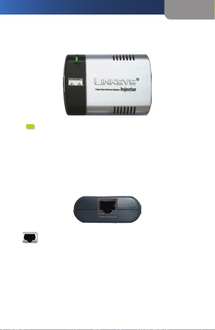
Injector
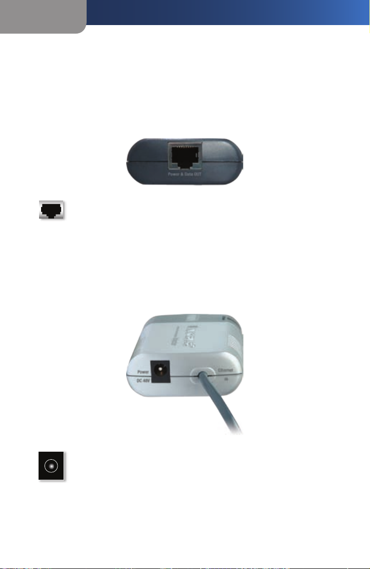
The Injector’s built-in cable and ports are located on side panels.
Injector’s First Side Panel
The Power & Data OUT port is located on the Injector’s first side panel.
Power & Data OUT This port allows you to connect the
Injector to the Splitter or a network device that supports inline
power. (You will use the included Ethernet network cable to
make this connection.)
Injector’s Second Side Panel
The built-in Ethernet network cable and Power port are located on the
Injector’s second side panel.
Power The Power port is where you will connect the included
adapter.
Ethernet IN The Injector has a built-in Ethernet network
cable. You will connect this cable to one of the Ethernet
network ports on your router or switch.
2
2
2
12 Volt Power Over Ethernet Adapter Kit
Page 7
Product Overview
Injector’s LED
The Power LED is located on the top of the Injector.
Power (Green) The Power LED lights up when the Injector is
powered on and ready for use.
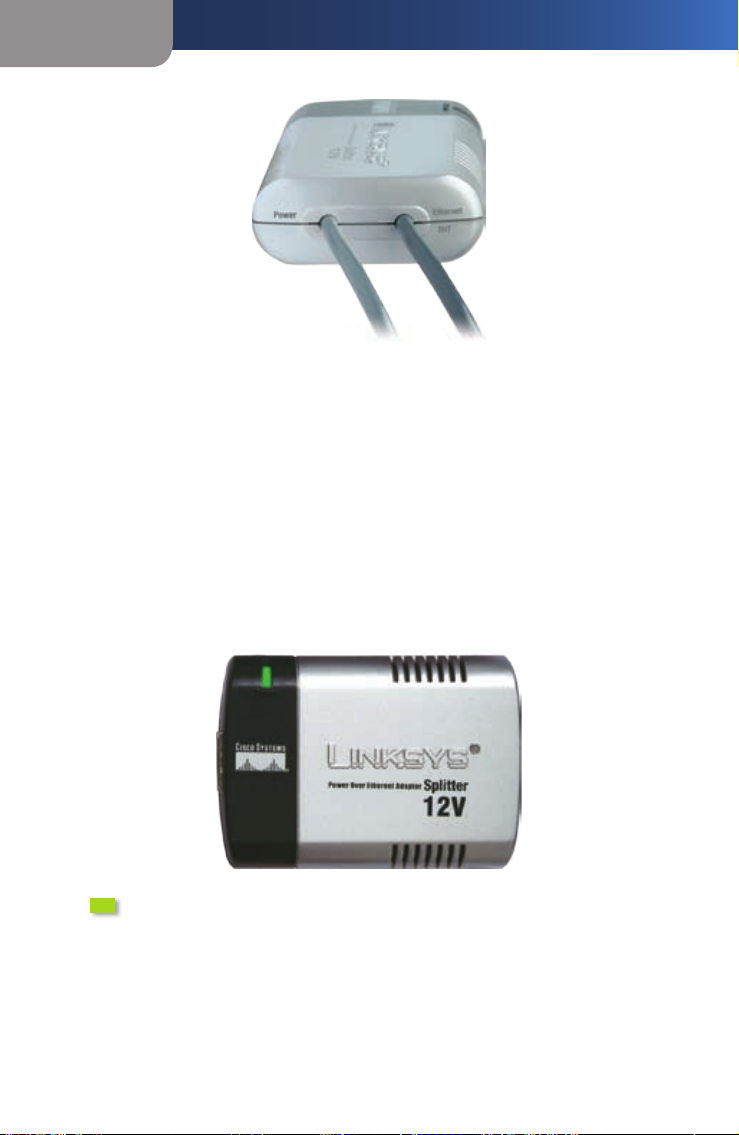
Splitter
The Splitter’s built-in cables and port are located on side panels.
Splitter’s First Side Panel
Chapter 1
The Power & Data IN port is located on the Injector’s first side panel.
Power & Data IN This port allows you to connect the Splitter
to the Injector. (You will use the included Ethernet network
cable to make this connection.)
Splitter’s Second Side Panel
The built-in Ethernet network and Power cables are located on the
Splitter’s second side panel.
12 Volt Power Over Ethernet Adapter Kit
3
3
Page 8
Chapter 1
Splitter’s LED
Product Overview
Ethernet OUT The Splitter has a built-in Ethernet network
cable. You will connect this cable to the Ethernet network
port of your remotely located access point or other network
device.
Power The Splitter has a built-in power cord. You will connect
this cord to the Power port of your remotely located access
point or other network device.
The Splitter’s LED is located on the top of the Splitter.
Power (Green) The Power LED lights up when the Splitter is
powered on and ready for use.
4
4
4
12 Volt Power Over Ethernet Adapter Kit
Page 9

Connection
Chapter 2
Chapter 2: Connection
Overview
This chapter gives instructions on how to connect the Power Over
Ethernet Kit. Once connected, the Kit will transmit data and power over
the Ethernet network cable to your remotely located network device.
The diagram shows an example of how the Kit can be connected to a
wired switch and a wireless access point.
Power Adapter
(24V typical)
Power Cable
Wireless
Access Point
Power Cable
Ethernet Cable
Network
Workgroup
Switch
Ethernet Cable
Power Over Ethernet
Ethernet Cable
Injector Splitter
Up to 328 feet
(100 m)
To connect the Kit to a device with a conventional power port, proceed
to the section, “Power on a Device that Uses a Standard Power Adapter.”
To connect the Injector to a device that supports inline power, proceed
to the section, “Power on a Device that Uses Inline Power.”
12 Volt Power Over Ethernet Adapter Kit
5
5
Page 10

Chapter 2
Connection
Power on a Device that Uses a Standard Power Adapter
Use the Injector and Splitter to power up a device that uses a standard
power adapter. Follow these instructions:
Connect the Injector’s built-in Ethernet network cable to your router,
1.
switch, or other network device.
Connect the Kit’s included Ethernet network cable to the Injector’s
2.
Power & Data OUT port.
NOTE: If this cable is not long enough, then you can use your
own Ethernet network cable.
Then connect the other end to the Splitter’s Power & Data IN port.
3.
Connect the Splitter’s built-in Ethernet network cable to the Ethernet
4.
port of your remotely located access point or other network device.
Connect the Splitter’s Power cord to the Power port of your remotely
5.
located access point or other network device.
6
6
6
12 Volt Power Over Ethernet Adapter Kit
Page 11

Connection
NOTE: If the plug of the Splitter’s Power cord does not fit
into your network device, then use the included barrel jack
adapter. Plug the Splitter’s Power cord into the jack end, and
plug the other end of the barrel jack adapter into the Power
port of your network device.
Connect the Kit’s power adapter to the Injector, and plug the other
6.
end into an electrical outlet or surge protector.
Congratulations! The installation of the 12 Volt Power Over
Ethernet Kit is complete.
Chapter 2
Power on a Device that Uses Inline Power
Use only the Injector to power up a device that supports inline power.
Follow these instructions:
Connect the Injector’s built-in Ethernet network cable to your router,
1.
switch, or other network device.
Connect the Kit’s included Ethernet network cable to the Injector’s
2.
Power & Data OUT port.
12 Volt Power Over Ethernet Adapter Kit
7
7
Page 12

Chapter 2
Then connect the other end to the Ethernet port of your remotely
3.
Connection
located access point or other network device.
NOTE: If the plug of the Splitter’s Power cord does not fit
into your network device, then use the included barrel jack
adapter. Plug the Splitter’s Power cord into the jack end, and
plug the other end of the barrel jack adapter into the Power
port of your network device.
Connect the Kit’s power adapter to the Injector, and plug the other
4.
end into an electrical outlet or surge protector.
Congratulations! The installation of the Power Over Ethernet Kit is
complete.
8
8
8
12 Volt Power Over Ethernet Adapter Kit
Page 13

Specifications
Appendix A: Specifications
Model WAPPOE12
Standards IEEE 802.3, 802.3u
Ports Injector: Power, Data and Power OUT
Splitter: Data and Power IN
Cabling Type Category 5 or better
LED Power
Environmental
Dimensions 3.15" x 0.87" x 2.20"
(80 x 22 x 56 mm)
Weight 2.65 oz. (0.075 kg)
Power External Adapter: 100~240VAC,
Injector 48VDC
Certication FCC Class B
Operating Temp. 32 to 104ºF (0 to 40ºC)
Storage Temp. -4 to 158ºF (–20 to 70ºC)
Operating Humidity 10 to 85% Noncondensing
Storage Humidity 5 to 90% Noncondensing
Appendix A
12 Volt Power Over Ethernet Adapter Kit
9
9
Page 14

Appendix A
Specifications
10
10
10
12 Volt Power Over Ethernet Adapter Kit
Page 15

Warranty Information
Appendix B
Appendix B: Warranty Information
Limited Warranty
Linksys warrants this Linksys hardware product against defects in materials and
workmanship under normal use for the Warranty Period, which begins on the date of
purchase by the original end-user purchaser and lasts for the period specified below:
One (1) year for new product
•
Ninety (90) days for refurbished product
•
This limited warranty is non-transferable and extends only to the original end-user
purchaser. Your exclusive remedy and Linksys’ entire liability under this limited warranty
will be for Linksys, at its option, to (a) repair the product with new or refurbished parts,
(b) replace the product with a reasonably available equivalent new or refurbished Linksys
product, or (c) refund the purchase price of the product less any rebates. Any repaired or
replacement products will be warranted for the remainder of the original Warranty Period
or thirty (30) days, whichever is longer. All products and parts that are replaced become
the property of Linksys.
Exclusions and Limitations
This limited warranty does not apply if: (a) the product assembly seal has been removed
or damaged, (b) the product has been altered or modified, except by Linksys, (c) the
product damage was caused by use with non-Linksys products, (d) the product has not
been installed, operated, repaired, or maintained in accordance with instructions supplied
by Linksys, (e) the product has been subjected to abnormal physical or electrical stress,
misuse, negligence, or accident, (f) the serial number on the Product has been altered,
defaced, or removed, or (g) the product is supplied or licensed for beta, evaluation, testing
or demonstration purposes for which Linksys does not charge a purchase price or license
fee.
ALL SOFTWARE PROVIDED BY LINKSYS WITH THE PRODUCT, WHETHER FACTORY LOADED
ON THE PRODUCT OR CONTAINED ON MEDIA ACCOMPANYING THE PRODUCT, IS PROVIDED
“AS IS” WITHOUT WARRANTY OF ANY KIND. Without limiting the foregoing, Linksys does
not warrant that the operation of the product or software will be uninterrupted or error
free. Also, due to the continual development of new techniques for intruding upon and
attacking networks, Linksys does not warrant that the product, software or any equipment,
system or network on which the product or software is used will be free of vulnerability
to intrusion or attack. The product may include or be bundled with third party software
or service offerings. This limited warranty shall not apply to such third party software or
service offerings. This limited warranty does not guarantee any continued availability of a
third party’s service for which this product’s use or operation may require.
TO THE EXTENT NOT PROHIBITED BY LAW, ALL IMPLIED WARRANTIES AND CONDITIONS OF
MERCHANTABILITY, SATISFACTORY QUALITY OR FITNESS FOR A PARTICULAR PURPOSE ARE
LIMITED TO THE DURATION OF THE WARRANTY PERIOD. ALL OTHER EXPRESS OR IMPLIED
12 Volt Power Over Ethernet Adapter Kit
11
11
Page 16

Appendix B
CONDITIONS, REPRESENTATIONS AND WARRANTIES, INCLUDING, BUT NOT LIMITED TO,
ANY IMPLIED WARRANTY OF NON-INFRINGEMENT, ARE DISCLAIMED. Some jurisdictions
do not allow limitations on how long an implied warranty lasts, so the above limitation
may not apply to you. This limited warranty gives you specific legal rights, and you may
also have other rights which vary by jurisdiction.
TO THE EXTENT NOT PROHIBITED BY LAW, IN NO EVENT WILL LINKSYS BE LIABLE FOR
ANY LOST DATA, REVENUE OR PROFIT, OR FOR SPECIAL, INDIRECT, CONSEQUENTIAL,
INCIDENTAL OR PUNITIVE DAMAGES, REGARDLESS OF THE THEORY OF LIABILITY
(INCLUDING NEGLIGENCE), ARISING OUT OF OR RELATED TO THE USE OF OR INABILITY TO
USE THE PRODUCT (INCLUDING ANY SOFTWARE), EVEN IF LINKSYS HAS BEEN ADVISED
OF THE POSSIBILITY OF SUCH DAMAGES. IN NO EVENT WILL LINKSYS’ LIABILITY EXCEED
THE AMOUNT PAID BY YOU FOR THE PRODUCT. The foregoing limitations will apply even if
any warranty or remedy provided under this limited warranty fails of its essential purpose.
Some jurisdictions do not allow the exclusion or limitation of incidental or consequential
damages, so the above limitation or exclusion may not apply to you.
Warranty Information
Obtaining Warranty Service
If you have a question about your product or experience a problem with it, please go
to www.linksys.com/support where you will find a variety of online support tools and
information to assist you with your product. If the product proves defective during the
Warranty Period, contact Linksys Technical Support for instructions on how to obtain
warranty service. The telephone number for Linksys Technical Support in your area can
be found in the product User Guide and at www.linksys.com. Have your product serial
number and proof of purchase on hand when calling. A DATED PROOF OF ORIGINAL
PURCHASE IS REQUIRED TO PROCESS WARRANTY CLAIMS. If you are requested to return
your product, you will be given a Return Materials Authorization (RMA) number. You are
responsible for properly packaging and shipping your product to Linksys at your cost and
risk. You must include the RMA number and a copy of your dated proof of original purchase
when returning your product. Products received without a RMA number and dated proof
of original purchase will be rejected. Do not include any other items with the product you
are returning to Linksys. Defective product covered by this limited warranty will be repaired
or replaced and returned to you without charge. Customers outside of the United States of
America and Canada are responsible for all shipping and handling charges, custom duties,
VAT and other associated taxes and charges. Repairs or replacements not covered under
this limited warranty will be subject to charge at Linksys’ then-current rates.
Technical Support
This limited warranty is neither a service nor a support contract. Information about Linksys’
current technical support offerings and policies (including any fees for support services)
can be found at: www.linksys.com/support.
This limited warranty is governed by the laws of the jurisdiction in which the Product was
purchased by you.
Please direct all inquiries to: Linksys, P.O. Box 18558, Irvine, CA 92623.
12
12
12
12 Volt Power Over Ethernet Adapter Kit
Page 17

Regulatory Information
Appendix C
Appendix C: Regulatory Information
FCC Statement
This product has been tested and complies with the specifications for
a Class B digital device, pursuant to Part 15 of the FCC Rules. These
limits are designed to provide reasonable protection against harmful
interference in a residential installation. This equipment generates, uses,
and can radiate radio frequency energy and, if not installed and used
according to the instructions, may cause harmful interference to radio
communications. However, there is no guarantee that interference will
not occur in a particular installation. If this equipment does cause harmful
interference to radio or television reception, which is found by turning
the equipment off and on, the user is encouraged to try to correct the
interference by one or more of the following measures:
Reorient or relocate the receiving antenna
•
Increase the separation between the equipment or devices
•
Connect the equipment to an outlet other than the receiver’s
•
Consult a dealer or an experienced radio/TV technician for
•
assistance
Safety Notices
Caution: To reduce the risk of fire, use only No.26 AWG or larger
telecommunication line cord.
Do not use this product near water, for example, in a wet basement or
near a swimming pool.
Avoid using this product during an electrical storm. There may be a
remote risk of electric shock from lightning.
WARNING: This product contains lead, known to the State
of California to cause cancer, and birth defects or other
reproductive harm. Wash hands after handling.
12 Volt Power Over Ethernet Adapter Kit
13
13
Page 18

Appendix C
Regulatory Information
Industry Canada Statement
This Class B digital apparatus complies with Canadian ICES-003.
Operation is subject to the following two conditions:
This device may not cause interference and
1.
This device must accept any interference, including interference that
2.
may cause undesired operation of the device.
Avis d’Industry Canada
Cet appareil est conforme à la norme NMB003 d’Industrie Canada.
Le fonctionnement est soumis aux conditions suivantes :
Ce périphérique ne doit pas causer d’interférences;
1.
Ce périphérique doit accepter toutes les interférences reçues,
2.
y compris celles qui risquent d’entraîner un fonctionnement
indésirable.
User Information for Consumer Products Covered by EU Directive 2002/96/EC on Waste Electric and Electronic Equipment (WEEE)
This document contains important information for users with regards
to the proper disposal and recycling of Linksys products. Consumers are
required to comply with this notice for all electronic products bearing
the following symbol:
14
14
14
12 Volt Power Over Ethernet Adapter Kit
Page 19

Regulatory Information
Appendix C
English - Environmental Information for Customers in the European
Union
European Directive 2002/96/EC requires that the equipment bearing this symbol
on the product and/or its packaging must not be disposed of with unsorted
municipal waste. The symbol indicates that this product should be disposed
of separately from regular household waste streams. It is your responsibility
to dispose of this and other electric and electronic equipment via designated
collection facilities appointed by the government or local authorities. Correct
disposal and recycling will help prevent potential negative consequences to
the environment and human health. For more detailed information about the
disposal of your old equipment, please contact your local authorities, waste
disposal service, or the shop where you purchased the product.
Български (Bulgarian) - Информация относно опазването на
околната среда за потребители в Европейския съюз
Европейска директива 2002/96/EC изисква уредите, носещи този символ
върху изделието и/или опаковката му, да не се изхвърля т с несортирани
битови отпадъци. Символът обозначава, че изделието трябва да се
изхвърля отделно от сметосъбирането на обикновените битови отпадъци.
Ваша е отговорността този и другите електрически и електронни уреди да
се изхвърлят в предварително определени от държавните или общински
органи специализирани пунктове за събиране. Правилното изхвърляне
и рециклиране ще спомогнат да се предотвратят евентуални вредни за
околната среда и здравето на населението последствия. За по-подробна
информация относно изхвърлянето на вашите стари уреди се обърнете към
местните власти, службите за сметосъбиране или магазина, от който сте
закупили уреда.
Ceština (Czech) - Informace o ochraně životního prostředí pro
zákazníky v zemích Evropské unie
Evropská směrnice 2002/96/ES zakazuje, aby zařízení označené tímto symbolem
na produktu anebo na obalu bylo likvidováno s netříděným komunálním
odpadem. Tento symbol udává, že daný produkt musí být likvidován odděleně
od běžného komunálního odpadu. Odpovídáte za likvidaci tohoto produktu a
dalších elektrických a elektronických zařízení prostřednictvím určených sběrných
míst stanovených vládou nebo místními úřady. Správná likvidace a recyklace
pomáhá předcházet potenciálním negativním dopadům na životní prostředí
a lidské zdraví. Podrobnější informace o likvidaci starého vybavení si laskavě
vyžádejte od místních úřadů, podniku zabývajícího se likvidací komunálních
odpadů nebo obchodu, kde jste produkt zakoupili.
12 Volt Power Over Ethernet Adapter Kit
15
15
Page 20

Appendix C
Regulatory Information
Dansk (Danish) - Miljøinformation for kunder i EU
EU-direktiv 2002/96/EF kræver, at udstyr der bærer dette symbol på produktet
og/eller emballagen ikke må bortskaffes som usorteret kommunalt affald.
Symbolet betyder, at dette produkt skal bortskaffes adskilt fra det almindelige
husholdningsaffald. Det er dit ansvar at bortskaffe dette og andet elektrisk og
elektronisk udstyr via bestemte indsamlingssteder udpeget af staten eller de
lokale myndigheder. Korrekt bortskaffelse og genvinding vil hjælpe med til at
undgå mulige skader for miljøet og menneskers sundhed. Kontakt venligst de
lokale myndigheder, renovationstjenesten eller den butik, hvor du har købt
produktet, angående mere detaljeret information om bortskaffelse af dit gamle
udstyr.
Deutsch (German) - Umweltinformation für Kunden innerhalb der
Europäischen Union
Die Europäische Richtlinie 2002/96/EC verlangt, dass technische Ausrüstung,
die direkt am Gerät und/oder an der Verpackung mit diesem Symbol versehen
ist , nicht zusammen mit unsortiertem Gemeindeabfall entsorgt werden darf.
Das Symbol weist darauf hin, dass das Produkt von regulärem Haushaltmüll
getrennt entsorgt werden sollte. Es liegt in Ihrer Verantwortung, dieses Gerät
und andere elektrische und elektronische Geräte über die dafür zuständigen und
von der Regierung oder örtlichen Behörden dazu bestimmten Sammelstellen
zu entsorgen. Ordnungsgemäßes Entsorgen und Recyceln trägt dazu bei,
potentielle negative Folgen für Umwelt und die menschliche Gesundheit zu
vermeiden. Wenn Sie weitere Informationen zur Entsorgung Ihrer Altgeräte
benötigen, wenden Sie sich bitte an die örtlichen Behörden oder städtischen
Entsorgungsdienste oder an den Händler, bei dem Sie das Produkt erworben
haben.
Eesti (Estonian) - Keskkonnaalane informatsioon Euroopa Liidus
asuvatele klientidele
Euroopa Liidu direktiivi 2002/96/EÜ nõuete kohaselt on seadmeid, millel on
tootel või pakendil käesolev sümbol , keelatud kõrvaldada koos sorteerimata
olmejäätmetega. See sümbol näitab, et toode tuleks kõrvaldada eraldi
tavalistest olmejäätmevoogudest. Olete kohustatud kõrvaldama käesoleva ja
ka muud elektri- ja elektroonikaseadmed riigi või kohalike ametiasutuste poolt
ette nähtud kogumispunktide kaudu. Seadmete korrektne kõrvaldamine ja
ringlussevõtt aitab vältida võimalikke negatiivseid tagajärgi keskkonnale ning
inimeste tervisele. Vanade seadmete kõrvaldamise kohta täpsema informatsiooni
saamiseks võtke palun ühendust kohalike ametiasutustega, jäätmekäitlusfirmaga
või kauplusega, kust te toote ostsite.
16
16
16
12 Volt Power Over Ethernet Adapter Kit
Page 21

Regulatory Information
Appendix C
Español (Spanish) - Información medioambiental para clientes de la
Unión Europea
La Directiva 2002/96/CE de la UE exige que los equipos que lleven este símbolo
en el propio aparato y/o en su embalaje no deben eliminarse junto con
otros residuos urbanos no seleccionados. El símbolo indica que el producto
en cuestión debe separarse de los residuos domésticos convencionales con
vistas a su eliminación. Es responsabilidad suya desechar este y cualesquiera
otros aparatos eléctricos y electrónicos a través de los puntos de recogida
que ponen a su disposición el gobierno y las autoridades locales. Al desechar
y reciclar correctamente estos aparatos estará contribuyendo a evitar posibles
consecuencias negativas para el medio ambiente y la salud de las personas.
Si desea obtener información más detallada sobre la eliminación segura de
su aparato usado, consulte a las autoridades locales, al servicio de recogida y
eliminación de residuos de su zona o pregunte en la tienda donde adquirió el
producto.
ξλληνικά (Greek) - Στοιχεία περιβαλλοντικής προστασίας για
πελάτες εντός της Ευρωπαϊκής Ένωσης
Η Κοινοτική Οδηγία 2002/96/EC απαιτεί ότι ο εξοπλισμός ο οποίος φέρει
αυτό το σύμβολο στο προϊόν και/ή στη συσκευασία του δεν πρέπει να
απορρίπτεται μαζί με τα μικτά κοινοτικά απορρίμματα. Το σύμβολο υποδεικνύει
ότι αυτό το προϊόν θα πρέπει να απορρίπτεται ξεχωριστά από τα συνήθη
οικιακά απορρίμματα. Είστε υπεύθυνος για την απόρριψη του παρόντος και
άλλου ηλεκτρικού και ηλεκτρονικού εξοπλισμού μέσω των καθορισμένων
εγκαταστάσεων συγκέντρωσης απορριμμάτων οι οποίες παρέχονται από
το κράτος ή τις αρμόδιες τοπικές αρχές. Η σωστή απόρριψη και ανακύκλωση
συμβάλλει στην πρόληψη πιθανών αρνητικών συνεπειών για το περιβάλλον και
την υγεία. Για περισσότερες πληροφορίες σχετικά με την απόρριψη του παλιού
σας εξοπλισμού, παρακαλώ επικοινωνήστε με τις τοπικές αρχές, τις υπηρεσίες
απόρριψης ή το κατάστημα από το οποίο αγοράσατε το προϊόν.
Français (French) - Informations environnementales pour les clients
de l’Union européenne
La directive européenne 2002/96/CE exige que l’équipement sur lequel est
apposé ce symbole sur le produit et/ou son emballage ne soit pas jeté avec les
autres ordures ménagères. Ce symbole indique que le produit doit être éliminé
dans un circuit distinct de celui pour les déchets des ménages. Il est de votre
responsabilité de jeter ce matériel ainsi que tout autre matériel électrique ou
électronique par les moyens de collecte indiqués par le gouvernement et les
pouvoirs publics des collectivités territoriales. L’élimination et le recyclage en
bonne et due forme ont pour but de lutter contre l’impact néfaste potentiel
de ce type de produits sur l’environnement et la santé publique. Pour plus
d’informations sur le mode d’élimination de votre ancien équipement, veuillez
prendre contact avec les pouvoirs publics locaux, le service de traitement des
déchets, ou l’endroit où vous avez acheté le produit.
12 Volt Power Over Ethernet Adapter Kit
17
17
Page 22

Appendix C
Regulatory Information
Italiano (Italian) - Informazioni relative all’ambiente per i clienti
residenti nell’Unione Europea
La direttiva europea 2002/96/EC richiede che le apparecchiature contrassegnate
con questo simbolo sul prodotto e/o sull’imballaggio non siano smaltite
insieme ai rifiuti urbani non differenziati. Il simbolo indica che questo prodotto
non deve essere smaltito insieme ai normali rifiuti domestici. È responsabilità del
proprietario smaltire sia questi prodotti sia le altre apparecchiature elettriche ed
elettroniche mediante le specifiche strutture di raccolta indicate dal governo o
dagli enti pubblici locali. Il corretto smaltimento ed il riciclaggio aiuteranno a
prevenire conseguenze potenzialmente negative per l’ambiente e per la salute
dell’essere umano. Per ricevere informazioni più dettagliate circa lo smaltimento
delle vecchie apparecchiature in Vostro possesso, Vi invitiamo a contattare gli
enti pubblici di competenza, il servizio di smaltimento rifiuti o il negozio nel
quale avete acquistato il prodotto.
Latviešu valoda (Latvian) - Ekoloģiska informācija klientiem Eiropas
Savienības jurisdikcijā
Direktīvā 2002/96/EK ir prasība, ka aprīkojumu, kam pievienota zīme uz paša
izstrādājuma vai uz tā iesaiņojuma, nedrīkst izmest nešķirotā veidā kopā ar
komunālajiem atkritumiem (tiem, ko rada vietēji iedzīvotāji un uzņēmumi). Šī
zīme nozīmē to, ka šī ierīce ir jāizmet atkritumos tā, lai tā nenonāktu kopā ar
parastiem mājsaimniecības atkritumiem. Jūsu pienākums ir šo un citas elektriskas
un elektroniskas ierīces izmest atkritumos, izmantojot īpašus atkritumu
savākšanas veidus un līdzekļus, ko nodrošina valsts un pašvaldību iestādes. Ja
izmešana atkritumos un pārstrāde tiek veikta pareizi, tad mazinās iespējamais
kaitējums dabai un cilvēku veselībai. Sīkākas ziņas par novecojuša aprīkojuma
izmešanu atkritumos jūs varat saņemt vietējā pašvaldībā, atkritumu savākšanas
dienestā, kā arī veikalā, kur iegādājāties šo izstrādājumu.
Lietuvškai (Lithuanian) - Aplinkosaugos informacija, skirta Europos
Sąjungos vartotojams
Europos direktyva 2002/96/EC numato, kad įrangos, kuri ir kurios pakuotė yra
pažymėta šiuo simboliu (įveskite simbolį), negalima šalinti kartu su nerūšiuotomis
komunalinėmis atliekomis. Šis simbolis rodo, kad gaminį reikia šalinti atskirai nuo
bendro buitinių atliekų srauto. Jūs privalote užtikrinti, kad ši ir kita elektros ar
elektroninė įranga būtų šalinama per tam tikras nacionalinės ar vietinės valdžios
nustatytas atliekų rinkimo sistemas. Tinkamai šalinant ir perdirbant atliekas, bus
išvengta galimos žalos aplinkai ir žmonių sveikatai. Daugiau informacijos apie
jūsų senos įrangos šalinimą gali pateikti vietinės valdžios institucijos, atliekų
šalinimo tarnybos arba parduotuvės, kuriose įsigijote tą gaminį.
18
18
18
12 Volt Power Over Ethernet Adapter Kit
Page 23

Regulatory Information
Appendix C
Malti (Maltese) - Informazzjoni Ambjentali għal Klijenti fl-Unjoni
Ewropea
Id-Direttiva Ewropea 2002/96/KE titlob li t-tagħmir li jkun fih is-simbolu fuq
il-prodott u/jew fuq l-ippakkjar ma jistax jintrema ma’ skart muniċipali li ma ġiex
isseparat. Is-simbolu jindika li dan il-prodott għandu jintrema separatament
minn ma’ l-iskart domestiku regolari. Hija responsabbiltà tiegħek li tarmi dan ittagħmir u kull tagħmir ieħor ta’ l-elettriku u elettroniku permezz ta’ faċilitajiet
ta’ ġbir appuntati apposta mill-gvern jew mill-awtoritajiet lokali. Ir-rimi b’mod
korrett u r-riċiklaġġ jgħin jipprevjeni konsegwenzi negattivi potenzjali għallambjent u għas-saħħa tal-bniedem. Għal aktar informazzjoni dettaljata dwar irrimi tat-tagħmir antik tiegħek, jekk jogħġbok ikkuntattja lill-awtoritajiet lokali
tiegħek, is-servizzi għar-rimi ta’ l-iskart, jew il-ħanut minn fejn xtrajt il-prodott.
Magyar (Hungarian) - Környezetvédelmi információ az európai
uniós vásárlók számára
A 2002/96/EC számú európai uniós irányelv megkívánja, hogy azokat a
termékeket, amelyeken, és/vagy amelyek csomagolásán az alábbi címke
megjelenik, tilos a többi szelektálatlan lakossági hulladékkal együtt kidobni.
A címke azt jelöli, hogy az adott termék kidobásakor a szokványos háztartási
hulladékelszállítási rendszerektõl elkülönített eljárást kell alkalmazni. Az Ön
felelõssége, hogy ezt, és más elektromos és elektronikus berendezéseit a
kormányzati vagy a helyi hatóságok által kijelölt gyűjtõredszereken keresztül
számolja fel. A megfelelõ hulladékfeldolgozás segít a környezetre és az emberi
egészségre potenciálisan ártalmas negatív hatások megelõzésében. Ha elavult
berendezéseinek felszámolásához további részletes információra van szüksége,
kérjük, lépjen kapcsolatba a helyi hatóságokkal, a hulladékfeldolgozási
szolgálattal, vagy azzal üzlettel, ahol a terméket vásárolta.
Nederlands (Dutch) - Milieu-informatie voor klanten in de Europese
Unie
De Europese Richtlijn 2002/96/EC schrijft voor dat apparatuur die is voorzien van
dit symbool op het product of de verpakking, niet mag worden ingezameld met
niet-gescheiden huishoudelijk afval. Dit symbool geeft aan dat het product apart
moet worden ingezameld. U bent zelf verantwoordelijk voor de vernietiging van
deze en andere elektrische en elektronische apparatuur via de daarvoor door
de landelijke of plaatselijke overheid aangewezen inzamelingskanalen. De juiste
vernietiging en recycling van deze apparatuur voorkomt mogelijke negatieve
gevolgen voor het milieu en de gezondheid. Voor meer informatie over het
vernietigen van uw oude apparatuur neemt u contact op met de plaatselijke
autoriteiten of afvalverwerkingsdienst, of met de winkel waar u het product
hebt aangeschaft.
12 Volt Power Over Ethernet Adapter Kit
19
19
Page 24

Appendix C
Regulatory Information
Norsk (Norwegian) - Miljøinformasjon for kunder i EU
EU-direktiv 2002/96/EF krever at utstyr med følgende symbol avbildet på
produktet og/eller pakningen, ikke må kastes sammen med usortert avfall.
Symbolet indikerer at dette produktet skal håndteres atskilt fra ordinær
avfallsinnsamling for husholdningsavfall. Det er ditt ansvar å kvitte deg med dette
produktet og annet elektrisk og elektronisk avfall via egne innsamlingsordninger
slik myndighetene eller kommunene bestemmer. Korrekt avfallshåndtering
og gjenvinning vil være med på å forhindre mulige negative konsekvenser for
miljø og helse. For nærmere informasjon om håndtering av det kasserte utstyret
ditt, kan du ta kontakt med kommunen, en innsamlingsstasjon for avfall eller
butikken der du kjøpte produktet.
Polski (Polish) - Informacja dla klientów w Unii Europejskiej o
przepisach dotyczących ochrony środowiska
Dyrektywa Europejska 2002/96/EC wymaga, aby sprzęt oznaczony symbolem
znajdującym się na produkcie i/lub jego opakowaniu nie był wyrzucany razem
z innymi niesortowanymi odpadami komunalnymi. Symbol ten wskazuje, że
produkt nie powinien być usuwany razem ze zwykłymi odpadami z gospodarstw
domowych. Na Państwu spoczywa obowiązek wyrzucania tego i innych urządzeń
elektrycznych oraz elektronicznych w punktach odbioru wyznaczonych przez
władze krajowe lub lokalne. Pozbywanie się sprzętu we właściwy sposób i jego
recykling pomogą zapobiec potencjalnie negatywnym konsekwencjom dla
środowiska i zdrowia ludzkiego. W celu uzyskania szczegółowych informacji
o usuwaniu starego sprzętu, prosimy zwrócić się do lokalnych władz, służb
oczyszczania miasta lub sklepu, w którym produkt został nabyty.
Português (Portuguese) - Informação ambiental para clientes da
União Europeia
A Directiva Europeia 2002/96/CE exige que o equipamento que exibe este símbolo
no produto e/ou na sua embalagem não seja eliminado junto com os resíduos
municipais não separados. O símbolo indica que este produto deve ser eliminado
separadamente dos resíduos domésticos regulares. É da sua responsabilidade
eliminar este e qualquer outro equipamento eléctrico e electrónico através das
instalações de recolha designadas pelas autoridades governamentais ou locais.
A eliminação e reciclagem correctas ajudarão a prevenir as consequências
negativas para o ambiente e para a saúde humana. Para obter informações mais
detalhadas sobre a forma de eliminar o seu equipamento antigo, contacte as
autoridades locais, os serviços de eliminação de resíduos ou o estabelecimento
comercial onde adquiriu o produto.
20
20
20
12 Volt Power Over Ethernet Adapter Kit
Page 25

Regulatory Information
Appendix C
Română (Romanian) - Informaţii de mediu pentru clienţii din
Uniunea Europeană
Directiva europeană 2002/96/CE impune ca echipamentele care prezintă acest
simbol pe produs şi/sau pe ambalajul acestuia să nu fie casate împreună cu
gunoiul menajer municipal. Simbolul indică faptul că acest produs trebuie să fie
casat separat de gunoiul menajer obişnuit. Este responsabilitatea dvs. să casaţi
acest produs şi alte echipamente electrice şi electronice prin intermediul unităţilor
de colectare special desemnate de guvern sau de autorităţile locale. Casarea
şi reciclarea corecte vor ajuta la prevenirea potenţialelor consecinţe negative
asupra sănătăţii mediului şi a oamenilor. Pentru mai multe informaţii detaliate
cu privire la casarea acestui echipament vechi, contactaţi autorităţile locale,
serviciul de salubrizare sau magazinul de la care aţi achiziţionat produsul.
Slovenčina (Slovak) - Informácie o ochrane životného prostredia pre
zákazníkov v Európskej únii
Podľa európskej smernice 2002/96/ES zariadenie s týmto symbolom na
produkte a/alebo jeho balení nesmie byť likvidované spolu s netriedeným
komunálnym odpadom. Symbol znamená, že produkt by sa mal likvidovať
oddelene od bežného odpadu z domácností. Je vašou povinnosťou likvidovať toto
i ostatné elektrické a elektronické zariadenia prostredníctvom špecializovaných
zberných zariadení určených vládou alebo miestnymi orgánmi. Správna
likvidácia a recyklácia pomôže zabrániť prípadným negatívnym dopadom na
životné prostredie a zdravie ľudí. Ak máte záujem o podrobnejšie informácie o
likvidácii starého zariadenia, obráťte sa, prosím, na miestne orgány, organizácie
zaoberajúce sa likvidáciou odpadov alebo obchod, v ktorom ste si produkt
zakúpili.
Slovenčina (Slovene) - Okoljske informacije za stranke v Evropski
uniji
Evropska direktiva 2002/96/EC prepoveduje odlaganje opreme, označene s
tem simbolom – na izdelku in/ali na embalaži – med običajne, nerazvrščene
odpadke. Ta simbol opozarja, da je treba izdelek odvreči ločeno od preostalih
gospodinjskih odpadkov. Vaša odgovornost je, da to in preostalo električno in
elektronsko opremo odnesete na posebna zbirališča, ki jih določijo državne
ustanove ali lokalna uprava. S pravilnim odlaganjem in recikliranjem boste
preprečili morebitne škodljive vplive na okolje in zdravje ljudi. Če želite izvedeti
več o odlaganju stare opreme, se obrnite na lokalno upravo, odpad ali trgovino,
kjer ste izdelek kupili.
12 Volt Power Over Ethernet Adapter Kit
21
21
Page 26

Appendix C
Regulatory Information
Suomi (Finnish) - Ympäristöä koskevia tietoja EU-alueen asiakkaille
EU-direktiivi 2002/96/EY edellyttää, että jos laitteistossa on tämä symboli itse
tuotteessa ja/tai sen pakkauksessa, laitteistoa ei saa hävittää lajittelemattoman
yhdyskuntajätteen mukana. Symboli merkitsee sitä, että tämä tuote on
hävitettävä erillään tavallisesta kotitalousjätteestä. Sinun vastuullasi on hävittää
tämä elektroniikkatuote ja muut vastaavat elektroniikkatuotteet viemällä
tuote tai tuotteet viranomaisten määräämään keräyspisteeseen. Laitteiston
oikea hävittäminen estää mahdolliset kielteiset vaikutukset ympäristöön ja
ihmisten terveyteen. Lisätietoja vanhan laitteiston oikeasta hävitystavasta saa
paikallisilta viranomaisilta, jätteenhävityspalvelusta tai siitä myymälästä, josta
ostit tuotteen.
Svenska (Swedish) - Miljöinformation för kunder i Europeiska
unionen
Det europeiska direktivet 2002/96/EC kräver att utrustning med denna symbol
på produkten och/eller förpackningen inte får kastas med osorterat kommunalt
avfall. Symbolen visar att denna produkt bör kastas efter att den avskiljts från
vanligt hushållsavfall. Det faller på ditt ansvar att kasta denna och annan
elektrisk och elektronisk utrustning på fastställda insamlingsplatser utsedda av
regeringen eller lokala myndigheter. Korrekt kassering och återvinning skyddar
mot eventuella negativa konsekvenser för miljön och personhälsa. För mer
detaljerad information om kassering av din gamla utrustning kontaktar du dina
lokala myndigheter, avfallshanteringen eller butiken där du köpte produkten.
22
22
22
WEB: For additional information, visit www.linksys.com
8021210B-JL
12 Volt Power Over Ethernet Adapter Kit
Page 27

Page 28

www.linksys.com
 Loading...