

Page 1

Instant WirelessTMSeries
Wireless Network
Access Point
Use this guide to install: WAP11 ver. 2.2
User Guide
Page 2

COPYRIGHT & TRADEMARKS
Copyright © 2002 Linksys, All Rights Reserved. Instant Wireless™ is a registered trademark of Linksys. Microsoft, Windows, and the Windows logo are registered trademarks
of Microsoft Corporation. All other trademarks and brand names are the property of their
respective proprietors.
LIMITED WARRANTY
Linksys guarantees that every Wireless Network Access Point is free from physical
defects in material and workmanship under normal use for one year from the date of purchase. If the product proves defective during this warranty period, call Linksys Technical
Support in order to obtain a Return Authorization Number. BE SURE TO HAVE YOUR
PROOF OF PURCHASE AND A BARCODE FROM THE PRODUCT’S PACKAGING ON
HAND WHEN CALLING. RETURN REQUESTS CANNOT BE PROCESSED WITHOUT
PROOF OF PURCHASE. When returning a product, mark the Return Authorization
Number clearly on the outside of the package and include a copy of your original proof
of purchase. All customers located outside of the United States of America and Canada
shall be held responsible for shipping and handling charges.
IN NO EVENT SHALL LINKSYS’ LIABILITY EXCEED THE PRICE PAID FOR THE PRODUCT FROM DIRECT, INDIRECT, SPECIAL, INCIDENTAL, OR CONSEQUENTIAL DAMAGES RESULTING FROM THE USE OF THE PRODUCT, ITS ACCOMPANYING SOFTWARE, OR ITS DOCUMENTATION. LINKSYS DOES NOT OFFER REFUNDS FOR ANY
PRODUCT. Linksys makes no warranty or representation, expressed, implied, or statutory, with respect to its products or the contents or use of this documentation and all
accompanying software, and specifically disclaims its quality, performance, merchantability, or fitness for any particular purpose. Linksys reserves the right to revise or
update its products, software, or documentation without obligation to notify any individual or entity. Please direct all inquiries to:
Linksys P.O. Box 18558, Irvine, CA 92623.
FCC STATEMENT
This product has been tested and complies with the specifications for a Class B digital
device, pursuant to Part 15 of the FCC Rules. These limits are designed to provide reasonable protection against harmful interference in a residential installation. This equipment generates, uses, and can radiate radio frequency energy and, if not installed and
used according to the instructions, may cause harmful interference to radio communications. However, there is no guarantee that interference will not occur in a particular
installation. If this equipment does cause harmful interference to radio or television
reception, which is found by turning the equipment off and on, the user is encouraged to
try to correct the interference by one or more of the following measures:
• Reorient or relocate the receiving antenna
• Increase the separation between the equipment or devices
• Connect the equipment to an outlet other than the receiver’s
• Consult a dealer or an experienced radio/TV technician for assistance
FCC Radiation Exposure Statement
This equipment complies with FCC radiation exposure limits set forth for an uncontrolled
environment. This equipment should be installed and operated with minimum distance
20cm between the radiator and your body.
UG-WAP11 ver. 2.2-081402C KL
Page 3

Wireless Network Access Point
Table of Contents
Chapter 1: Introduction 1
The Instant WirelessTMNetwork Access Point 1
Features 1
Package Contents 2
System Requirements 2
Chapter 2: Planning Your Wireless Network 3
Network Topology 3
Roaming 3
Chapter 3: Getting to Know the Wireless Network Access Point 4
The Wireless Network Access Point’s Ports 4
The Wireless Network Access Point’s LEDs 5
Chapter 4: Connecting the Wireless Network Access Point 6
Chapter 5: Setting Up the Wireless Network Access Point 7
Chapter 6: Configuring the Wireless Network Access Point 14
The Setup Tab 14
The Password Tab 19
The Status Tab 20
The Help Tab 22
The Filter Tab 23
The Wireless Tab 25
Appendix A: Troubleshooting 28
Frequently Asked Questions 28
Appendix B: Setting Up the TCP/IP Protocol 32
Setting Up TCP/IP in Windows 32
TCP/IP Setup for Windows 95, 98, and Millennium 33
TCP/IP Setup for Windows NT 4.0 34
TCP/IP Setup for Windows 2000 35
Appendix C: Glossary 36
INDUSTRY CANADA (CANADA)
This Class B digital apparatus complies with Canadian ICES-003.
Cet appareil numérique de la classe B est conforme à la norme NMB-003 du Canada.
The use of this device in a system operating either partially or completely outdoors may require
the user to obtain a license for the system according to the Canadian regulations.
EC DECLARATION OF CONFORMITY (EUROPE)
Linksys Group declares that the Instant Wireless™ Series products included in the Instant
Wireless™ Series conform to the specifications listed below, following the provisions of the EMC
Directive 89/336/EEC and Low Voltage Directive 73/23/EEC:
ETS 300-826, 301 489-1 General EMC requirements for Radio equipment.
EN 609 50 Safety
ETS 300-328-2 Technical requirements for Radio equipment.
Note: This equipment is intended to be used in all EU and EFTA countries. Outdoor use may
be restricted to certain frequencies and/or may require a license for operation. For more
details, contact Linksys Corporate Compliance.
Note: Combinations of power levels and antennas resulting in a radiated power level of above
100 mW are considered as not compliant with the above mentioned directive and are not
allowed for use within the European community and countries that have adopted the European
R&TTE directive 1999/5/EC and/or the CEPT recommendation Rec 70.03. For more details on
legal combinations of power levels and antennas, contact Linksys Corporate Compliance.
Linksys Group™ vakuuttaa täten että Instant Wireless IEEE 802.11 PC Card tyyppinen laite on
direktiivin 1999/5/EY, direktiivin 89/336/EEC ja direktiivin 73/23/EEC oleellisten vaatimusten ja
sitä koskevien näiden direktiivien muiden ehtojen mukainen.
Linksys Group™ déclare que la car te PC Instant Wireless IEEE 802.11 est conforme aux conditions essentielles et aux dispositions relatives à la directive 1999/5/EC, la directive
89/336/EEC, et à la directive 73/23/EEC.
Belgique B L’utilisation en extérieur est autorisé sur le canal 11 (2462 MHz), 12 (2467 MHz), et
13 (2472 MHz).
Dans le cas d’une utilisation privée, à l’extérieur d’un bâtiment, au-dessus d’un espace public,
aucun enregistrement n’est nécessaire pour une distance de moins de 300m. Pour une distance supérieure à 300m un enregistrement auprès de l’IBPT est requise. Pour une utilisation
publique à l’extérieur de bâtiments, une licence de l’IBPT est requise. Pour les enregistrements
et licences, veuillez contacter l’IBPT.
France F: Bande de fréquence restreinte: seuls les canaux 10, 11, 12, 13 (2457, 2462, 2467,
et 2472 MHz respectivement) doivent être utilisés en France.
Toute utilisation, qu'elle soit intérieure ou extérieure, est soumise à autorisation. Vous pouvez
contacter l'Autorité de Régulation des Télécommuniations
(<http://www.art-telecom.fr>) pour la procédure à suivre.
France F: Restricted frequency band: only channels 10, 11, 12, 13 (2457, 2462, 2467, and
2472 MHz respectively) may be used in France. License required for every indoor and outdoor
installations. Please contact ART for procedure to follow.
Deutschland D: Anmeldung im Outdoor-Bereich notwending, aber nicht genehmigungspflichtig. Bitte mit Händler die Vorgehensweise abstimmen.
Germany D: License required for outdoor installations. Check with reseller for procedure to follow
Italia I: E' necessaria la concessione ministeriale anche per l'uso interno. Verificare con i rivenditori la procedura da seguire. L'uso per installazione in esterni non e' permessa.
Italy I: License required for indoor use. Use with outdoor installations not allowed.
the Netherlands NL License required for outdoor installations. Check with reseller for procedure to follow.
Nederlands NL Licentie verplicht voor gebruik met buitenantennes. Neem contact op met
verkoper voor juiste procedure
Page 4

Wireless Network Access Point
Chapter 1: Introduction
The Instant WirelessTMNetwork Access Point
Don’t be bound by cabling restrictions any longer! The Instant Wireless™
Network Access P oint from Linksys deliv ers the freedom to configure your network yourway. Utilization of state-of-the-art wireless technology gives you the
ability to set up workstations in ways you never thought possible; no cables to
install means fewer expenses and fewer hassles.
The Instant Wireless™ Network Access Point’s high-powered antennae offer a
range of operation of up to 1500 feet, providing seamless roaming throughout
your LAN infrastructure. Advanced user authentication ensures a high level of
security for wireless networking, while easy-to-use W indo ws-based diagnostics
and statistics tools ensure that you’ll always be in control. Best of all, the
Instant Wireless™ Network Access Point features easy installation—just plug
it in and you’re ready to go!
When all these features come together in one compact, lightweight, and powerefficient unit, you have the ultimate in flexible networking—the Linksys
Instant Wireless™ Network Access Point.
Features
• Highly Efficient Dipole Antennae Provide Extensive Range of Operation
• Enjoy Your Wireless Off ice Beyond the Range of Ethernet Networking
• Auto Fall-Back Data Rate for Long-Distance Communication and Noisy
Environments
• High-Speed Data Transfer Rate Up to 11 Mbps
• Interoperable with IEEE 802.11b (DSSS) 2.4GHz-Compliant Equipment
• Features Roaming and Network Traffic Filtering
• Extensive Operating Range Supports up to 300 ft. (Indoors) and 500 feet
(Outdoors)
• Up to 256-Bit Wired Equivalent Privacy Supported
• Free Software Driver Upgrades
• Compatible with Virtually All Major Operating Systems
• Free Technical Support—24 Hours a Day, 7 Days a Week for North America
Only
• 1-Year Limited Warranty
1
Appendix D: Specifications 44
Environmental 45
Appendix E: Warranty Information 46
Appendix F: Contact Information 47
Instant WirelessTMSeries
Page 5
Wireless Network Access Point
3
Chapter 2: Planning Your
Wireless Network
A wireless LAN is a group of computers, each equipped with one Instant
Wireless™ Series adapter. Computers in a wireless LAN must be conf igured
to share the same radio channel.
The Instant Wireless™ Series adapters pro vide access to a wired LAN for wireless workstations. An integrated wireless and wired LAN is called an
Infrastructure configuration. A group of Instant Wireless™ Series adapter
users and an Instant Wireless™ Wireless Network Access Point compose a
Basic Service Set (BSS). Each Instant Wireless™ Series adapter PC in a BSS
can talk to any computer in a wired LAN infrastructure via the Instant
Wireless™ Wireless Network Access Point.
An infrastructure configuration extends the accessibility of an Instant
Wireless™ Series adapter PC to a wired LAN, and doubles the effective wireless transmission range for two Instant Wireless™ Series adapter PCs. Since
the Wireless Network Access Point is able to forward data within its BSS, the
effective transmission range in an infrastructure LAN is doubled.
Infrastructure mode also supports roaming capabilities for mobile users. More
than one BSS can be configured as an Extended Service Set (ESS). This continuous network allows users to roam freely. All PCs equipped with an Instant
Wireless™ Series adapter must be configured with the same SSID and use the
same radio channel.
Before enabling a network with roaming capability, choosing a feasible radio
channel and optimum Wireless Network Access Point position is recommended. Proper Wireless Network Access Point positioning combined with a clear
radio signal will greatly enhance performance.
Instant WirelessTMSeries
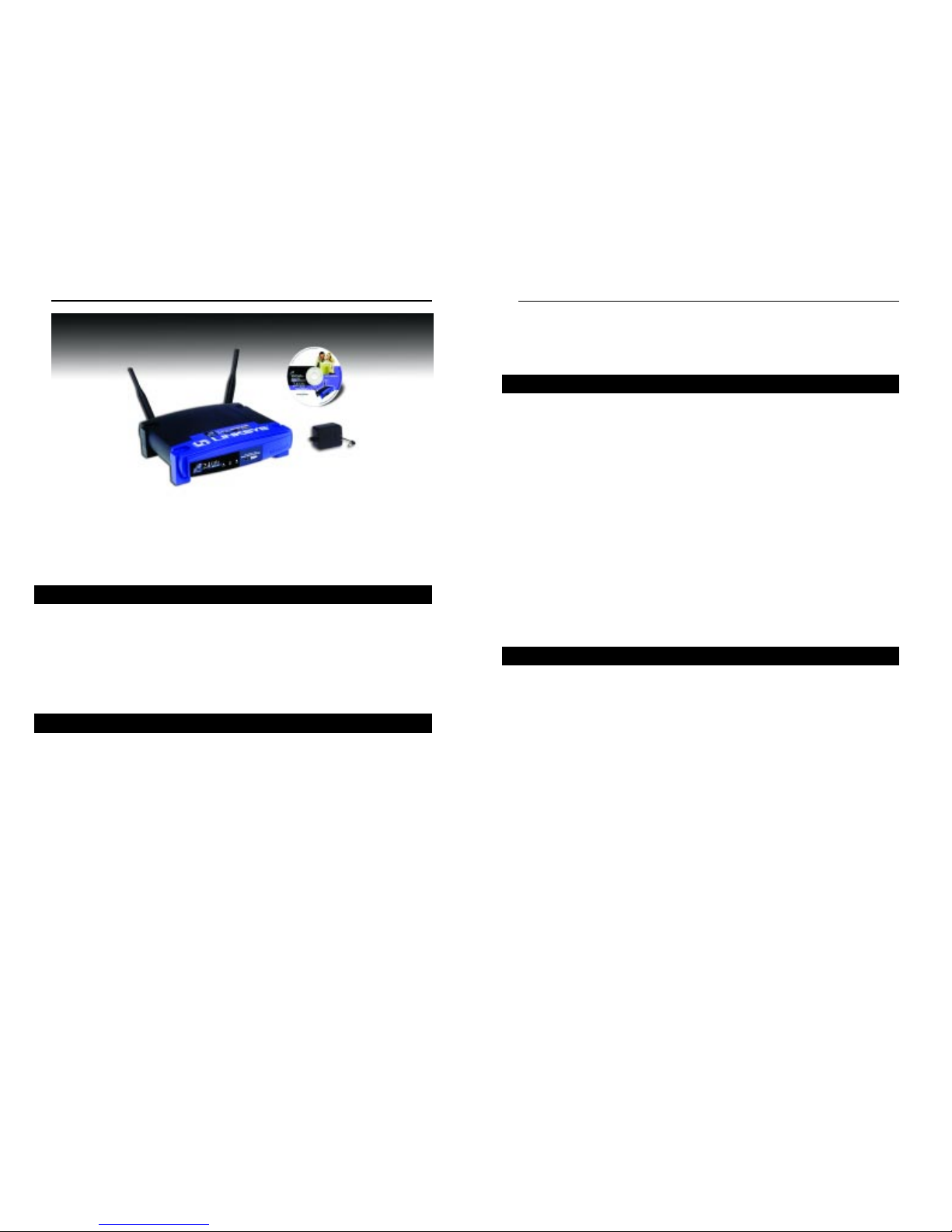
Package Contents
• One Instant WirelessTMWireless Network Access Point
• One AC Pow er Adapter
• One Setup Wizard CD-ROM (with User Guide)
• Two Detachable Antennae
• One Quick Installation and Registration Card (not shown)
• One CAT 5 Ethernet Cable (not shown)
System Requirements
• A Windows 95, 98, Millennium, NT version 4.0, 2000, or XP PC
• Internet Explorer ver. 4.0 or higher
• One CD-ROM Drive
2
Roaming
Figure 1-1
Network Topology
Page 6
Wireless Network Access Point
Instant WirelessTMSeries
Chapter 3: Getting to Know the
Wireless Network Access Point
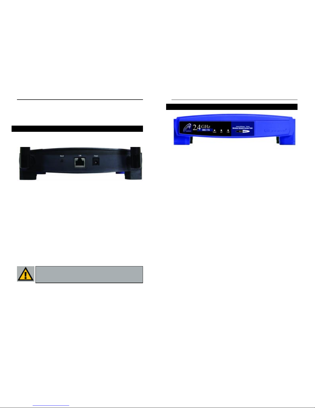
The Access Point’s ports, where a network cable is connected, are located on
the Access Point’s rear panel.
Dipole Antenna
Connectors These two round connections are where the antennae are
connected to the Access Point.
LAN This LAN (Local Area Network) port connects to
Ethernet network devices, such as a hub, switch, or
router.
Power The Power port is where you will connect the power
adapter.
Reset Button There are two ways to Reset the Access Point’s factory
defaults. Briefly press the Reset Button for approximately
ten seconds, or use the Password tab of the Access Point’s
Web-Based Utility.
4
The Wireless Network Access Point’s Ports
Figure 3-1
T
Power Red. The Powe r LED lights up when the Access Point is
powered on.
ACT Green. If the LED is flickering, the Access Point is actively
sending or receiving data to or from one of the devices on the
network.
LINK Amber. The LINK LED ser ves two purposes. If the LED is
continuously lit up, the Access Point is successfully connected to a device through the LAN port. If the LED is flickering, it is an indication of any network activity.
The Wireless Network Access Point’s LEDs
Figure 3-2
Important: Resetting the Access Point will erase all of your settings
(WEP Encryption, Wireless and LAN settings, etc.) and replace
them with the factory defaults.
5
Page 7

Chapter 5: Setting Up the
Wireless Network Access Point
Now that you’ve connected the Access Point to your wired network, you are
ready to begin setting it up. This Setup Wizard will take you through all the
steps necessary to get the Access Point connecting your wireless network to
your wired network and communicating more efficiently.
1. Insert the Setup Wizard CD into your PC’s CD-ROM driv e. Optimall y, your
PC should be on your wired network.
2. The screen in Figure 5-1 should appear on your monitor. If it does not, this
means the autorun is not functioning. Start the autorun manually by clicking the Start button, selecting Run, and typing d:\setup.exe (where “D” is
your PC’s CD-ROM drive). Click the Setup button to continue this Setup
Wizard. Clicking the User Guide button opened this User Guide. To access
the Linksys web site on an active Internet connection, click the Linksys
We b button or to exit this Setup Wizard, click the Exit button.
Chapter 4: Connecting the
Wireless Network Access Point
1. Locate an optimum location for the Access Point.The best place for the
Access Point is usually at the center of your wireless network, with line of
sight to all of your mobile stations.
2. Fix the direction of the antenna. Try to place it in a position which can
best cover your wireless network. Normally, the higher you place the antenna, the better the performance will be. The antenna’s position enhances the
receiving sensitivity. Both antennae should be perpendicular to the ground
and parallel to each other.
3. Connect a standard Ethernet network cable to the Access Point. Then,
connect the other end of the Ethernet cable to a switch or hub. The Access
Point will then be connected to your 10/100 Network.
4. Connect the AC Power Adapter to the Access Point’s Power Socket.
Only use the power adapter supplied with the Access Point. Use of a different adapter may result in product damage.
Now that the hardware installation is complete, proceed to Chapter 5:Setting
Up the Wireless Network Access Point for directions on how to setup the
Access Point.
6
Wireless Network Access Point
Instant WirelessTMSeries
Have You: Connected the Access Point to a hub, switch or router
on your wired network as shown in Chapter 4: Connecting the
Note: While the Access Point has been designed to work correctly right out of the box, setting it up on a wireless computer will
require you to use the Linksys default settings. These settings can
then be changed with the Web-based Browser Utility.
Note: In order for all other wireless devices to communicate with
the Access Point, those devices must be operating in the
Infrastructure Mode. If any wireless devices are conf igured in
the Ad Hoc Mode, they will not be recognized by the Access P oint.
7
Page 8

9
3. The following screen, shown in F igure 5-2, displays how there are two wa ys
to configure the Access Point in this Setup Wizard. Optimally, you should
perform this setup through a PC on your wired network. You can also set up
the Access Point through one of the PCs on your wireless network. Click
the Next button to continue or Exit to exit the Setup Wizard.
8
4. The next screen to appear, shown in Figure 5-3, will display a list of access
points on your network along with the status information for each access
point. If this is the only access point on your network, it will be the onl y one
displayed. If there are more than one displayed, select the Access Point by
clicking on it and click the Yes button to continue or No to exit the Setup
Wizard.
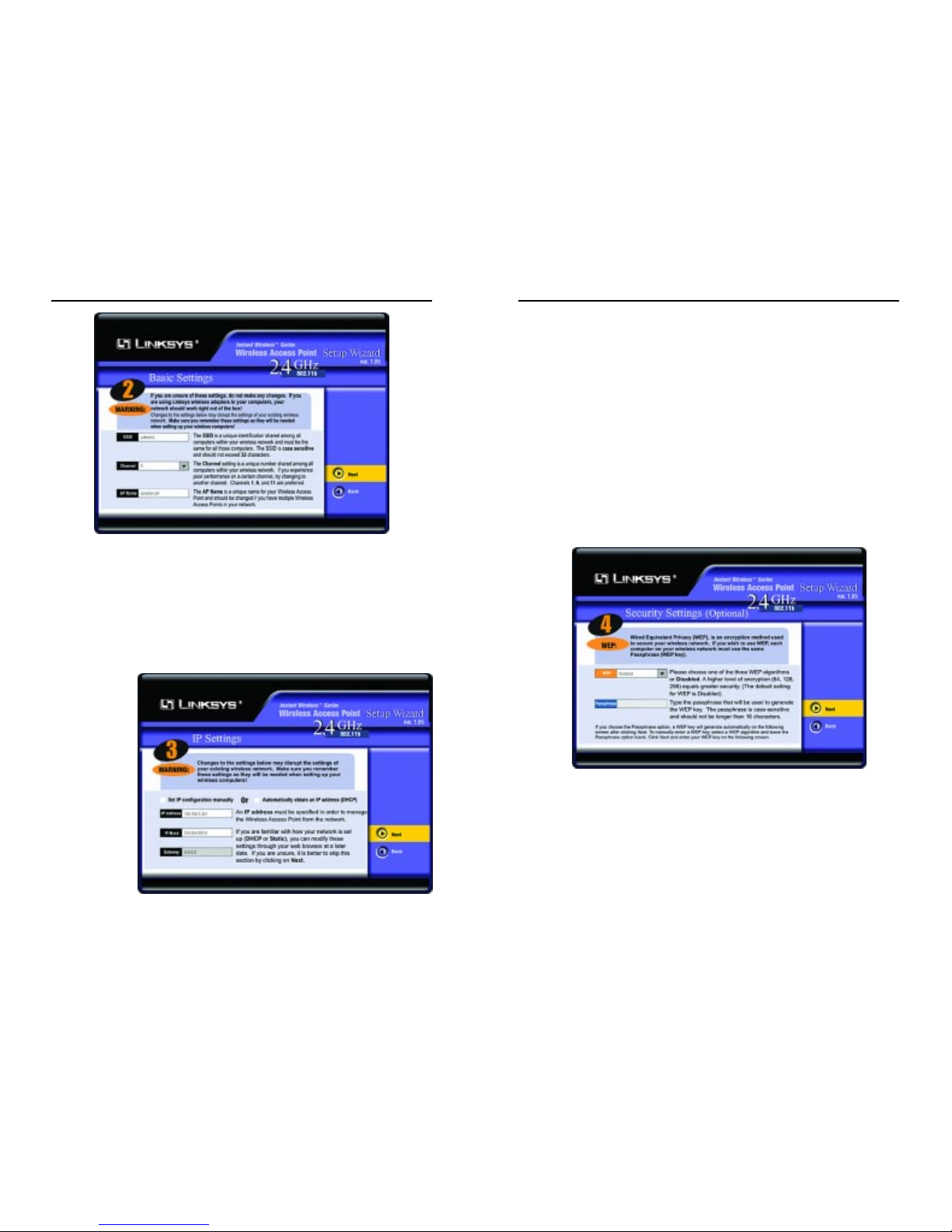
5. As shown in Figure 5-4, the Basic Settings screen will now appear. Enter
your wireless network’s SSID, select the channel at which the network
broadcasts its wireless signal, and enter a unique access point name for the
Access Point. Then, click the Next button to continue or Back to previous
page.
• SSID. The SSID is the unique name shared among all points in a wire-
less network. The SSID must be identical for all points in the wireless
network. It is case sensitive and must not exceed 32 characters, which
may be any keyboard character. Make sure this setting is the same for all
points in your wireless network.
• Channel. Select the appropriate channel from the list provided to corre-
spond with your network settings, between 1 and 11 (in North America).
All points in your wireless network must use the same channel in order
to function correctly.
Wireless Network Access PointInstant WirelessTMSeries
Figure 5-2
Figure 5-3
Figure 5-1
Page 9
• IP Address. This IP address must be unique to your network. (The
default IP address of 192.168.1.251.) As this is a private IP address,
there is no need to purchase a separate IP address from your service
provider.
• IP Mask. The Access Point’s IP Mask (also known as a Subnet Mask)
must be the same as your Ethernet network.
• Gateway. This setting only appears when the DHCP, Automatically
obtain an IP Address, option is enabled; it indicates the status of the
gateway and is not user-adjustable.
7. The Security Settings screen (Figure 5-6) will appear next. From this
screen, you will set the Wired Equivalent Privacy (WEP) encryption for
your wired network. Select a WEP configuration method and a passphrase.
Then, click the Next button to continue or Back to previous page.
• WEP (Disable/64-bit WEP/128-bit WEP/256-bit WEP). In order to
utilize WEP encryption, select the WEP setting from the pull-down
menu. If you do not wish to utilize WEP encryption, make sure Disable
is selected. The Access Point’s WEP encryption is unique to Linksys and
may conflict with other vendors’WEP encryption.
11
• Access Point Name. You may assign any name to the Access Point.
Unique, memorable names are helpful, especially if you are employing
multiple access points on the same network.
6. As shown in Figure 5-5, the IP Settings screen will appear next. Unless your network has a DHCP server, you will want to click the radio button beside Set IP
Address Manually to select this option. Enter an IP Address and IP Mask appropriate to your network. Then, click the Next button to continue or Back to previous page.
10
Wireless Network Access Point
Instant WirelessTMSeries
Figure 5-5
Figure 5-6
Figure 5-4
Page 10

• Passphrase. This is the code used when logging a wireless device onto
the wireless network. It is a text string with a maximum of 16 alphanumeric characters. The WEP Key Settings are based upon the Passphrase
determined by you. Type that here. This passphrase may not work with
non-Linksys products due to possible incompatibility with other vendors’
passphrase generators.
8. The following Security Settings screen, shown in F igure 5-7, will allow you
to enter your WEP key. Each point in your wireless network must use the
same WEP key for the network to function properly. Verify that the appropriate key is entered and click the Next button to continue or Back to previous page.
12
Instant WirelessTMSeries
Wireless Network Access Point
9. The next screen (Figure 5-8) will allow y ou to re vie w y our settings. If these
settings are correct, click the Yes button to save these settings. If there are
any problems with the settings, click the No button and you will return to
the screen shown in Figure 5-2.
10. At this point, the configuration performed with the Setup Wizard is complete, as shown in Figure 5-9. To configure any other Access Points in your
network, you can run this Setup Wizard again. Click the Exit button to exit
the Setup Wizard.
13
Figure 5-9
Figure 5-7
Figure 5-8
Page 11

14
• Obtain an IP Address Automatically.Click this radio button to allow the
Access Point to obtain a dynamic IP address from a DHCP server.
• Specify an IP Address. This IP address must be unique to your network.
W e suggest y ou use the default IP address of 192.168.1.251. As this is a private IP address, there is no need to purchase a separate IP address from
your service provider. Verify the address and click the Apply button to save
changes.
• Subnet Mask. The Access Point’s Subnet Mask (or IP Mask) must be the
same as your Ethernet network. Verify this is correct and click the Apply
button to set it.
• Gateway. This setting only appears when the DHCP client is enabled and
the IP Address is obtained automatically. It indicates the status of the gateway and is not user-adjustable.
15
Wireless Network Access Point
Instant WirelessTMSeries
Chapter 6: Configuring the
Wireless Network Access Point
The Access Point has been designed to be functional right out of the box, with
the default settings in the Setup Wizard. However, if you’d like to change these
settings, the Access P oint can be configured through your web bro wser with the
Web-Based Utility. This chapter explains how to configure the Access Point in
this manner.
Open your web browser
and type the IP Address
you entered in the Setup
Wizard. Press the Enter
key and the following
screen, shown in Figure
6-1, will appear. Leave
the User Name field
blank. The first time
you open the WebBased Utility, use the
default password
admin. You can set a
new password on the
screen shown in Figure
6-7.
The first screen that appears, shown in Figure 6-2, is the “Setup” tab. This
allows you to change the Access Point’s general settings. Change these settings
as described here and click the Apply button to apply your changes or Cancel
to cancel your changes. If you require online help, click the Help button.
• Access Point Name. You may assign any name to the Access Point.
Unique, memorable names are helpful, especially if you are employing
multiple access points on the same network. Verify this is the name you
wish to use and click the Apply button to set it.
Figure 6-1
Figure 6-2
The Setup Tab
Note: The Access Point is designed to function properly after
using the Setup Wizard. This chapter is provided solely for those
who wish to perform more advanced configuration or monitoring.
Page 12

The Mode pull-down menu will allow y ou to set the Passphrase in He xadecimal
or ASCII characters. Hexadecimal characters on your keyboard are the letters
“A” through “F” and the numbers “0” through “9”, while ASCII characters are
any character on your keyboard.
There are two wa ys to create WEP Encryption keys. The first method is by typing a Passphrase into that field and clicking the Generate button. This will generate WEP Encryption keys based upon that passphrase. A second method is to
type the WEP Encryption key in the available fields manually.
SETTING THE AP MODE:
The Access Point offers four modes of operation: Access Point, Access Point
Client, Wireless Bridge, and Wireless Bridge Point to MultiPoint. For all bridging modes, make sure the channel, SSID, and WEP keys are the same.
• Access Point - The Operational Mode is set to Access Point by default.
This connects your wireless PCs to a wired network. In most cases, no
change is necessary.
• Access Point Client - When set to Access Point Client mode, the Access Point
Client is able to talk to one remote access point within its range. This mode
allows the Access Point Client to act as a client of a remote access point. The
Access Point Client cannot communicate directly with any wireless clients. A
separate network attached to the Access Point Client can then be wirelessly
bridged to the remote access point. Enter the required LAN MAC address of the
remote access point.
Wireless Network Access Point
17
• SSID. The SSID is the unique name shared among all points in a wire-
less network. The SSID must be identical for all points in the wireless
network. It is case sensitive and must not exceed 32 alphanumeric characters, which may be any k eyboard character. Make sure this setting is the
same for all points in your wireless network.
• Channel. Select the appropriate channel from the list provided to corre-
spond with your network settings, between 1 and 11 (in North America).
All points in your wireless network must use the same channel in order
to function correctly.
• WEP. The WEP Encr yption method is Disabled by default. To enable
WEP, or make it mandatory, click the WEP Key Settingbutton.
Clicking the Backup button will store the Access Point’s configuration to your
PC’s hard drive. You can restore this information by clicking the Restore button.
Click the Apply button to apply your changes or Cancel to cancel your
changes. If you require online help, click the Help button.
SETTING WEP ENCRYPTION:
Setting WEP Encryption through
the Web-based Browser Utility is
done by clicking the WEP Key
Setting button on the Setup
Screen as shown in Figure 6-2.
A screen will pop up, asking you to confirm the WEP change to mandatory, as
shown in Figure 6-3. Click the OK button to enable WEP Encryption or
Cancel to return to the Setup Screen.
This will open the WEP Key Setting screen, Figure 6-4. From this screen, you
can select the type of WEP encryption to use as well as set the Passphrase for
that encryption.
From the pull-down menu at the top of the screen, select 64-bit, 128-bit, or 256bit encryption.
Instant WirelessTMSeries
16
Figure 6-3
Important: Always remember that each point in your wireless network MUST use the same WEPEncr yption method and encr yption
key or your wireless network will not function properly.
Figure 6-4
Page 13

Wireless Network Access Point
Only one of the Access Points must be in Point to MultiPoint mode. For all
other bridged Access Points, select the Point to Point option, and enter the
Remote LAN MAC Address of the Access Point set to Point to MultiPoint.
Click the Apply button to apply your changes or Cancel to cancel your
changes. If you require online help, click the Help button.
The “Password” tab, shown in Figure 6-7, allows you to change the Access
Point’s password and restore factory def aults.
Changing the sign-on password for the Access Point is as easy as typing the
password into the AP Password field. Then, type it again into the second field
to confirm.
To restore the Access Point’s factory default settings, click the Yes button
beside Restore Factory Defaults.
19
Instant Wireless™ Series
• Wireless Bridge - If you are trying to make a wireless connection between
two wired networks, as shown in Figure 6-5, select Wireless Bridge. This
mode connects two physically separated LAN segments with two Access
Points.
To configure a Wireless Bridge environment, click Wireless Bridge and
enter the Remote Bridge LAN MAC Address of the remote Access Point.
The remote Access Point also needs to be set up as a Wireless Bridge.
Note: All devices on each wired network must be connected through a hub
or switch.
• Wireless BridgePoint to MultiPoint- If you are trying to make a wireless
connection between more than two wired networks, as shown in Figure 66, select Wireless Bridge Point to MultiPoint. This mode allows you to
construct a network that has multiple Access Points bridging wirelessly.
To configure a Wireless Bridge Point to MultiPoint environment, click
Wireless Bridge Point to MultiPoint for the Access Point used in LAN 1.
No MAC Address binding is needed. Then, set the Access Points in LAN 2
and LAN 3 to Point to Point, and have them look for the MAC Address of
18
The Password Tab
Important: Restoring the Access Point’s factory defaults will erase
all of your settings (WEP Encryption, Wireless and LAN settings,
etc.), replacing them with the factory defaults. Do not reset the
Access Point if you want to retain these settings
Note: In Wireless Bridge mode, the Access Point can ONLY be
accessed by another access point in Wireless Bridge mode. In order
for your other wireless devices to access the Access Point, you must
reset it to Access P oint mode. The two modes are mutually exclusiv e.
Figure 6-5
Note: Linksys recommends bridging no more than three remote
LANs in Wireless Bridge Point to MultiPoint mode. Bridging additional remote LANs will result in a significant decrease in bandwidth.
Figure 6-6
Page 14

Wireless Network Access Point
• SSID. The unique name shared among all points in your wireless network
is displayed here.
• Encryption Function. The encryption method you chose in the Setup
Wizard or changed from the Setup Tab of this Web-based Utility is displayed here.
• Channel. The wireless channel shared by all wireless devices connected to
this Access Point is displayed here.
• Send and Recv. The Send and Recv fields under the Wireless’s status dis-
play the amount of packets sent and received. Some packet loss is normal
in wireless networking.
21
Instant Wireless™ Series
Click the Apply button to apply your changes or Cancel to cancel your
changes. If you require online help, click the Help button.
The “Status” tab, shown in Figure 6-8, will display current infor mation on the
Access Point, its settings and performance.
• Firmware Version. This displays the current version of the Access Point’s
firmware. Firmware should only be upgraded if you experience problems
with the Access Point and can be upgraded from the Help tab.
• IP Address. This IP address is the unique address to your network.
• Subnet Mask. The Access Point’s Subnet Mask (also known as a IP Mask),
which is the same as your Ethernet network.
• Gateway. This setting indicated the Network’s Gateway mask, only applicable when DHCP is enabled.
• Send and Recv. The Send and Recv fields under the LAN’s status display
the amount of packets sent and received. Some packet loss is normal in
wireless networking.
20
Figure 6-8
Figure 6-7
The Status Tab
Page 15

Wireless Network Access Point
The following resources require an Internet connection in order to access them.
Click the Linksys Website link to connect to the Linksys homepage for
Knowledgebase help files and information about other Linksys products.
For an Online Manual in PDFformat, click that text link. The manual will appear
in Adobe pdf format. If you do not have the Adobe PDF Reader installed on your
computer, click the Adobe Website link or go to the Setup Wizard CD-ROM to
download this software. To download from the CD-R OM, click the Startbutton and
select Run. Type D:\Acrobat(where “D” is the letter of your CD-ROM drive).
Firmware can be upgraded by clicking the Upgrade Firmwar elink. Do not upgrade
your firmware unless you are experiencing problems with the Access Point.
The “Filter” tab, shown in Figure 6-11, allows you to block or allow certain computers, by their MACAddress, from communicating with the Access Point.
To enable f iltering of computers by their MAC Addresses, click the Enable radio
button. To disable this feature, click the radio button by Disable.
23
Instant Wireless™ Series
To view a log of the Access Point’s activity, select the “Log” tab, shown in
Figure 6-9.
To enable logging activity, click the Enable radio button beside Access Log.
The default setting for this function is Disable.
The Send Log to option designates from which PC you can view the log. Third
party “View Log” software is required to take advantage of this option.
To view the log, click the View Log button.
Click the Apply button to apply your changes or Cancel to cancel your
changes. If you require online help, click the Help button.
For help on the various tabs in this Web-based Utility, along with upgrading the
Access Point’s firmware and viewing this User Guide, click the “Help” tab,
shown in Figure 6-10.
The help files for the various tabs in this Web-based Utility are listed by tab
name on the left hand side of the screen.
22
Figure 6-10
The Filter Tab
The Log Tab
Figure 6-9
The Help Tab
Page 16

Wireless Network Access Point
Before making any changes to the Wireless tab, shown in Figure 6-12, please
check your wireless settings on other systems, as these changes will alter the
effectiveness of the Access Point. In most cases, these settings do not need to
be changed.
• Beacon Interval. This value indicates the frequency interval of the beacon.
A beacon is a packet broadcast by the Access P oint to keep the network synchronized. A beacon includes the wireless LAN service area, the AP
address, the Broadcast destination addresses, a time stamp, Delivery T raf fic
Indicator Maps, and the Traff ic Indicator Message (TIM).
• RTS Threshold. This value should remain at its default setting of 2,432.
Should you encounter inconsistent data flow, only minor modifications are
recommended.
25
Instant Wireless™ Series
Next, determine if the Access P oint will den yaccess only to the MAC addresses you
will specify, OR if the Access Point will allow access only to the MAC Addresses
you will specify. Click the radio button next to the option that is appropriate.
Above the MAC Address fields, there is a pull-down menu. This pull-down
menu is for selecting the number of computers on your wireless network. For
computers one through ten on your wireless network, 1~10 is selected by
default. If you have more than ten computers on your wireless network, use this
pull-down menu to select 11~20, 21~30, etc., up to a maximum of 50 MAC
Addresses.
Then, type the MAC Address(es) you wish to filter in the MAC Address fields.
When you’ve completed making any changes on this tab, click the Apply button to save those changes or Undo to exit the Web-based Utility without saving
changes. For more information on this tab, you can click the Help button.
24
The Wireless Tab
Figure 6-12
Figure 6-11
Page 17

Wireless Network Access Point
• SSID Broadcast. For security purposes, this selection can be disabled,
allowing only those wireless network cards with the Access Point’s SSID to
communicate with the Access Point. By default, this selection is enabled,
allowing all wireless network cards in your wireless network to communicate with the Access Point.
When you’ve completed making any changes on this tab, click the Apply button to save those changes or Cancel to exit the Web-based Utility without saving changes. For more information on this tab, you can click the Help button.
2726
Important: The Access Point will not be recognized by “site-survey” utilities, such as the Microsoft®Windows®XP Zero
Configuration Utility, if SSID Broadcast is disabled.
• Fragmentation Threshold. This specifies the maximum size a data packet will be before splitting and creating a new packet and should remain at
its default setting of 2,346. A smaller setting means smaller packets, which
will create more packets for each transmission. Only minor modifications
of this value are recommended.
• DTIM Interval. This value indicates the interval of the Delivery Traffic
Indication Message (DTIM). A DTIM field is a countdown field informing
clients of the next window for listening to broadcast and multicast messages. When the Access Point has buffered broadcast or multicast messages
for associated clients, it sends the next DTIM with a DTIM Interval value.
Access Point Clients hear the beacons and awaken to receive the broadcast
and multicast messages.
• Transmission Rates. The basic transfer rates should be set depending on
the speed of your wireless network. You must select 1-2 (MBps) if you have
older 802.11 compliant equipment on your network, such as wireless
adapters that support only 1 or 2 Mbps. Selecting 1-2 (MBps), however,
does not limit the basic transfer rates of faster adapters.
• Preamble Type. The preamble def ines the length of the CRC block for
communication between the Access Point and a roaming Network Card.
(High network traffic areas should use the shorter preamble type.) Select
the appropriate preamble type and click the Applybutton to set it. All wireless points (nodes) on your network should use the same preamble type.
• Authentication Type. You may choose between Open System, Shared
Key, and Both. The Authentication Type default is set to Open System.
Shared Key is when both the sender and the recipient share a secret key.
All points on your network must use the same authentication type. It is recommended that you use the default setting.
• Antenna Selection. This selection is for choosing which antenna transmits
data. By default, the Diversity Antenna selection, used to increase reception, is chosen.
Instant WirelessTMSeries
Page 18

Wireless Network Access Point
What is Infrastructure?
An integrated wireless and wired LAN is called an Infrastructure configuration. Infrastructure is applicable to enterprise scale for wireless access to a central database, or wireless application for mobile workers.
What is Roaming?
Roaming is the ability of a portable computer user to communicate continuously while moving freely throughout an area greater than that covered by a
single Access Point. Before using the roaming function, the workstation must
make sure that it is the same channel number as the Access Point of the dedicated coverage area.
To achieve true seamless connectivity, the wireless LAN must incorporate a
number of different functions. Each node and Access Point, for example, must
alwa ys acknowledge receipt of each message. Each node must maintain contact
with the wireless network even when not actually transmitting data. Achieving
these functions simultaneously requires a dynamic RF networking technology
that links Access P oints and nodes. In such a system, the user’s end node undertakes a search for the best possible access to the system. First, it evaluates such
factors as signal strength and quality, as well as the message load currently
being carried by each Access P oint and the distance of each Access Point to the
wired backbone. Based on that information, the node next selects the right
Access Point and registers its address. Communications between end node and
host computer can then be transmitted up and down the backbone.
As the user moves on, the end node’s RF transmitter regularly checks the system to determine whether it is in touch with the original Access Point or
whether it should seek a new one. When a node no longer receives acknowledgment from its original Access Point, it undertakes a new search. Upon finding a new Access Point, it then re-registers, and the communication process
continues.
What is BSS ID?
A specific Ad-hoc LAN is called a Basic Service Set (BSS). Computers in a
BSS must be configured with the same BSS ID.
What is ESSID?
An Infrastructure configuration could also support roaming capability for
mobile workers. More than one BSS can be configured as an Extended Service
Set (ESS). Users within an ESS could roam freely between BSSs while maintaining a continuous connection to the wireless network stations and Access
Points.
29
Instant Wireless™ Series
Appendix A: Troubleshooting
This chapter provides solutions to problems usually encountered during the
installation and operation of the Access Point. Read the description below to
solve your problems. If you can’t find an answer here, check the Linksys website at www.linksys.com.
Can the Access Point act as my DHCP Server?
No. The Access Point is nothing more than a wireless hub, and as such, cannot
be configured to handle DHCP capabilities.
Can I run an application from a remote computer over the wireless network?
This will depend on whether or not the application is designed to be used over
a network. Consult the application’s user guide to determine if it supports operation over a network.
Can I play multiplayer games with other users of the wireless network?
Yes, as long as the game supports multiple players over a LAN (local area network). Refer to the game’s user guide for more information.
What is the IEEE 802.11b standard?
The IEEE 802.11b Wireless LAN standards subcommittee is formulating a
standard for the industry. The objective is to enable wireless LAN hardware
from different manufacturers to communicate.
What IEEE 802.11 features are supported?
The product supports the following IEEE 802.11 functions:
• CSMA/CA plus Acknowledge protocol
• Multi-Channel Roaming
• Automatic Rate Selection
• RTS/CTS feature
• Fragmentation
• Power Management
What is Ad-hoc?
An Ad-hoc wireless LAN is a group of computers, each with a WLAN adapter ,
connected as an independent wireless LAN. An Ad-hoc wireless LAN is applicable at a departmental scale for a branch or SOHO operation.
28
Frequently Asked Questions
Page 19

Wireless Network Access Point
Can Instant WirelessTMproducts support file and printer sharing?
Instant WirelessTMproducts perform the same function as LAN products.
Therefore, Instant WirelessTMproducts can work with Netware, Windows
NT/2000, or other LAN operating systems to support printer or file sharing.
What is WEP?
WEP is Wired Equivalent Privacy, a data privacy mechanism based on a 40 bit
shared key algorithm, as described in the IEEE 802.11 standard.
What is a MAC Address?
The Media Access Control (MAC) address is a unique number assigned by the
manufacturer to any Ethernet networking device, such as a network adapter,
that allows the network to identify it at the hardw are le vel. For all practical purposes, this number is usually permanent. Unlike IP addresses, which can
change every time a computer logs on to the network, the MAC address of a
device stays the same, making it a valuable identif ier for the network.
31
Instant Wireless™ Series
What is ISM band?
The FCC and their counterparts outside of the U.S. have set aside bandwidth
for unlicensed use in the ISM (Industrial, Scientific and Medical) band.
Spectrum in the vicinity of 2.4 GHz, in particular, is being made available
worldwide. This presents a truly revolutionary opportunity to place convenient
high speed wireless capabilities in the hands of users around the globe.
What is Spread Spectrum?
Spread Spectrum technology is a wideband radio frequency technique developed by the military for use in reliable, secure, mission-critical communications systems. It is designed to trade off bandwidth efficiency for reliability,
integrity, and security. In other words, more bandwidth is consumed than in the
case of narrowband transmission, but the trade-off produces a signal that is, in
effect, louder and thus easier to detect, provided that the receiver knows the
parameters of the spread-spectrum signal being broadcast. If a receiver is not
tuned to the right frequency, a spread-spectrum signal looks like background
noise. There are two main alternatives, Direct Sequence Spread Spectrum
(DSSS) and Frequency Hopping Spread Spectrum (FHSS).
What is DSSS? What is FHSS? And what are their differences?
Frequency Hopping Spread Spectrum (FHSS) uses a narrowband carrier that
changes frequency in a pattern that is known to both transmitter and receiver.
Properly synchronized, the net effect is to maintain a single logical channel. To
an unintended receiver, FHSS appears to be short-duration impulse noise.
Direct Sequence Spread Spectrum (DSSS) generates a redundant bit pattern for
each bit to be transmitted. This bit pattern is called a chip (or chipping code).
The longer the chip, the greater the probability that the original data can be
recovered. Even if one or more bits in the chip are damaged during transmission, statistical techniques embedded in the radio can recover the original data
without the need for retransmission. To an unintended receiver, DSSS appears
as low power wideband noise and is rejected (ignored) by most narrowband
receivers.
Would the information be intercepted while transmitting on air?
WLAN features two-fold protection in security. On the hardware side, as with
Direct Sequence Spread Spectrum technology, it has the inherent security feature of scrambling. On the software side, the WLAN series offers the encryption function (WEP) to enhance security and access control. Users can set it up
depending upon their needs.
30
Page 20

Wireless Network Access Point
The following instructions are provided as examples for reference only. For
complete instructions on installing and troubleshooting TCP/IP, consult your
Windows operating system documentation.
1. Click the Start button, select Settings, and open the Control Panel. Inside
the Control Panel, double-click the Network icon.
2. If the TCP/IP Protocol is listed for your network adapter, go to step five.
Otherwise, click the Add button.
3. When the Component Typewindow appears, select Protocol and click the
Add button.
4. Select Microsoft in the Manufacturers list and choose TCP/IP in the
Network Protocols list. Then, click the OK button.
5. When the Network window reappears, click TCP/IP and then click the
Properties button.
6. Select Specify an IP Address.
7. Enter an IP Address for the computer, along with a Subnet Mask. Click the
OK button. If you do not have these values, consult your network administrator.
8. When the Network window reappears, click the OK button. Restar t your
machine. TCP/IP has now been successfully installed.
33
Instant Wireless™ Series
Appendix B: Setting Up the TCP/IP
Protocol
Before a computer can communicate with the Access Point, it must be configured with the TCP/IP protocol. If you know how to set up TCP/IP on your computers, do so now. Otherwise, use the guidelines below to help get TCP/IP
installed on all of the computers that need to communicate with the Access
Point. If you are unable to successfully install TCP/IP on one or more computers after following the directions, contact the manufacturer of your computers'
network operating system for further assistance. Check with your network
administrator for your TCP/IP settings.
The directions below provide general guidelines for coming up with IP addresses and subnet masks. Check with your network administrator to see if you need
to use specific IP addresses or DHCP settings.
First, each computer on the network will require an IP address, which is a series
of numbers, separated by periods, identifying the PC on the network. To make
things simple, it is recommended you use the following numbering scheme:
192.168.1.X
In this example, X is a unique, arbitrarily assigned number from 1 to 254. Each
computer must have its o wn unique X number. Note: Never use 0 or 255 for X.
These numbers are reserved by TCP/IP for other uses.
For example, if you have three computers, you could number them as follows:
192.168.1.17
192.168.1.44
192.168.1.126
In this case, 17, 44, and 126 are arbitrary numbers between 1 and 254.
Each computer will also require a subnet mask, which is a numerical “filter”
that tells a computer what kinds of TCP/IP data packets to accept. If you’re not
sure which mask to use, the following mask is recommended:
255.255.255.0
32
TCP/IP Setup for Windows 95, 98, and Millennium
Setting Up TCP/IP in Windows
Page 21

Wireless Network Access Point
1. At the Windows 2000 desktop, right click My Network Places. Then, right
click Local Area Connection. Choose Properties.
2. If the TCP/IP Protocol is listed for your network adapter, go to step five.
Otherwise, click the Install button.
3. When the Component Typewindow appears, select Protocol, and click the
Install button.
4. Select Internet Protocol (TCP/IP) from the list and click the OK button.
5. When the Network window reappears, select TCP/IP, and click the
Properties button.
6. Select Use the following IP Address.
7. Enter an IP Address for the computer, along with a Subnet Mask and
Default Gateway. Then, click the OK button. If you do not have these values, consult your network administrator.
8. When the Network window reappears, click the OK button. Restart your
computer. TCP/IP has now been successfully installed.
35
Instant Wireless™ Series
1. Click the Start button, select Settings, and open the Control Panel. Inside
the Control Panel, double-click the Network icon.
2. When the Network window appears, click the Protocols tab. Then, click
the Add button.
3. Find the TCP/IP protocol in the Select Network Protocol f ield. Click on
it once and then click the OK button.
4. When asked if you want to use DHCP, choose No.
5. If asked to supply your Windows NT CD, do so. NT will copy the necessary files to your system. You may have to switch between the Access
Point’s Setup CD and the NT CD.
6. When TCP/IP appears in the Network Protocols window, click the
Bindings tab. Windows will store your new bindings.
7. Click the Protocols tab. Then, select TCP/IP.
8. Click the Properties button. Select the type of network adapter you have
from the Adapters box and select Specify an IP Address.
9. Enter the computer’s IP Address and Subnet Mask. Check with your network administrator for your settings.
10. Enter your Default Gateway if you have one.
11. When you finish, click the OK button. If NT asks about WINS, ignore it.
12. When the Network window reappears, click the Close button. Restart your
computer when prompted. TCP/IP has now been successfully installed.
34
TCP/IP Setup for Windows 2000TCP/IP Setup for Windows NT 4.0
NNoottee::
a Default Gateway is not required. Check with your network administrator.
Page 22

considered by the buffer designer. Like a cache, a buffer is a "midpoint holding place" but exists not so much to accelerate the speed of an activity as to
support the coordination of separate activities.
CSMA/CA (Carrier Sense Multiple Access/Collision Avoidance) - In local
area networking, this is the CSMA technique that combines slotted time-division multiplexing with carrier sense multiple access/collision detection
(CSMA/CD) to avoid having collisions occur a second time. This works best if
the time allocated is short compared to packet length and if the number of situations is small.
CSMA/CD (Carrier Sense Multiple Access/Collision Detection) - The LAN
access method used in Ethernet. When a device wants to gain access to the
network, it checks to see if the network is quiet (senses the carrier). If it is not,
it waits a random amount of time before retrying. If the network is quiet and
two devices access the line at exactl y the same time, their signals collide. When
the collision is detected, they both back off and each wait a random amount of
time before retrying.
Database - A database is a collection of data that is organized so that its contents can easily be accessed, managed, and updated.
DHCP (Dynamic Host Configuration Protocol) - A protocol that lets network
administrators manage centrally and automate the assignment of Internet
Protocol (IP) addresses in an organization's network. Using the Internet's set of
protocol (TCP/IP), each machine that can connect to the Internet needs a
unique IP address. When an organization sets up its computer users with a connection to the Internet, an IP address must be assigned to each machine.
Without DHCP, the IP address must be entered manually at each computer and,
if computers move to another location in another part of the network, a new IP
address must be entered. DHCP lets a network administrator supervise and distribute IP addresses from a central point and automatically sends a new IP
address when a computer is plugged into a different place in the network.
DHCP uses the concept of a "lease" or amount of time that a given IP address
will be valid for a computer. The lease time can vary depending on how long a
user is likely to require the Internet connection at a particular location. It's especially useful in education and other environments where users change frequently. Using very short leases, DHCP can dynamically reconfigure networks
in which there are more computers than there are available IP addresses.
DHCP supports static addresses for computers containing Web servers that
need a permanent IP address.
Wireless Network Access Point
3736
Instant WirelessTMSeries
Appendix C: Glossary
Adapter - Printed circuit board that plugs into a PC to add to capabilities or
connectivity to a PC. In a networked environment, a network interface card is
the typical adapter that allows the PC or server to connect to the intranet and/or
Internet.
Ad-hoc Network- An ad-hoc network is a wireless network or other small network in which some of the network devices are part of the network only for the
duration of a communications session while in some close proximity to the rest
of the network.
Backbone - The part of a network that connects most of the systems and networks together and handles the most data.
Bandwidth - The transmission capacity of a given facility, in terms of how
much data the facility can transmit in a fixed amount of time; expressed in bits
per second (bps).
Beacon Interval - A beacon is a packet broadcast by the Access Point to keep
the network synchronized. A beacon includes the wireless LAN service area,
the AP address, the Broadcast destination addresses, a time stamp, Delivery
Traffic Indicator Maps, and the Traff ic Indicator Message (TIM).
Bit - A binary digit. The value - 0 or 1-used in the binary numbering system.
Also, the smallest form of data.
Browser - A browser is an application program that provides a way to look at
and interact with all the information on the World Wide Web or PC. The word
"browser" seems to have originated prior to the Web as a generic term for user
interfaces that let you browse text files online.
BSS (Basic Service Set) - A group of wireless Network PC Card users and an
Access Point.
Buffer - A buffer is a shared or assigned memory area used by hardware
devices or program processes that operate at different speeds or with different
sets of priorities. The buffer allows each device or process to operate without
being held up by the other. In order for a buffer to be effective, the size of the
buffer and the algorithms for moving data into and out of the buffer need to be
Page 23

FHSS (Frequency Hopping Spread Spectrum) - FHSS continuously changes
the center frequency of a conventional carrier several times per second according to a pseudo-random set of channels, while chirp spread spectrum changes
the carrier frequency. Because a fixed frequency is not used, illegal monitoring
of spread spectrum signals is extremely difficult, if not downright impossible
depending on the particular method.
Firmware - Programming that is inserted into programmable read-only memory (programmable read-only memory), thus becoming a permanent part of a
computing device.
Fragmentation - Breaking a packet into smaller units when transmitting over
a network medium that cannot support the original size of the packet.
Gateway - A device that interconnects networks with different, incompatible
communications protocols.
Hardware - Hardware is the physical aspect of computers, telecommunications, and other information technology devices. The term arose as a wa y to distinguish the "box" and the electronic circuitry and components of a computer
from the program you put in it to make it do things. The program came to be
known as the software.
Hub - The device that serves as the central location for attaching wires from
workstations. Can be passive, where there is no amplification of the signals; or
active, where the hubs are used like repeaters to provide an extension of the
cable that connects to a workstation.
IEEE (The Institute of Electrical and Electronics Engineers) - The IEEE
describes itself as "the world's largest technical professional society, promoting
the development and application of electrotechnology and allied sciences for
the benefit of humanity, the advancement of the profession, and the well-being
of our members."
The IEEE fosters the development of standards that often become national and
international standards. The organization publishes a number of journals, has
many local chapters, and several large societies in special areas, such as the
IEEE Computer Society.
Infrastructure- An infrastructure network is a wireless network or other small
network in which the wireless network devices are made a part of the network
through the Access Point which connects them to the rest of the network.
Wireless Network Access Point
39
Instant WirelessTMSeries
38
Download - To receive a file transmitted over a network. In a communications
session, download means receive, upload means transmit.
Driver - A workstation or server software module that provides an interface
between a device and the upper-layer protocol software running in the computer; it is designed for a specific device, and is installed during the initial installation of a network-compatible client or server operating system.
DSSS (Direct-Sequence Spread-Spectrum) - DSSS generates a redundant bit
pattern for each bit to be transmitted. This bit pattern is called a chip (or chipping code). The longer the chip, the greater the probability that the original data
can be recovered. Even if one or more bits in the chip are damaged during
transmission, statistical techniques embedded in the radio can recover the original data without -the need for retransmission. To an unintended receiver, DSSS
appears as low power wideband noise and is rejected (ignored) by most narrowband receivers.
DTIM (Delivery Traffic Indication Message) - A DTIM field is a countdown
field informing clients of the next window for listening to broadcast and multicast messages. When the AP has buffered broadcast or multicast messages for
associated clients, it sends the next DTIM with a DTIM Interval value. AP
Clients hear the beacons and awaken to receive the broadcast and multicast
messages.
Dynamic IP Address - An IP address that is automatically assigned to a client
station in a TCP/IP network, typically by a DHCP server. Network devices that
serve multiple users, such as servers and printers, are usually assigned static IP
addresses.
Encryption - A security method that applies a specific algorithm to data in
order to alter the data's appearance and prevent other devices from reading the
information.
ESS - More than one BSS in a network.
Ethernet - IEEE standard network protocol that specifies how data is placed
on and retrieved from a common transmission medium. Has a transfer rate of
10 Mbps. Forms the underlying transport vehicle used by several upper-level
protocols, including TCP/IP and XNS.
Page 24

Wireless Network Access Point
Passphrase - Used much like a password, a passphrase simplifies the WEP
encryption process by automatically generating the WEP encryption keys for
Linksys products.
PC Card - A credit-card sized removable module that contains memory, I/O,
or a hard disk.
Port - A pathway into and out of the computer or a network device such as a
switch or router. For example, the serial and parallel ports on a personal computer are external sockets for plugging in communications lines, modems and
printers.
RJ-45 (Registered Jack-45) - A connector similar to a telephone connector that
holds up to eight wires, used for connecting Ethernet devices.
Roaming - The ability to use a wireless device and be able to move from one
access point's range to another without losing the connection.
Router - Protocol-dependent device that connects subnetworks together.
Routers are useful in breaking down a very large network into smaller subnetworks; they introduce longer delays and typically have much lower throughput
rates than bridges.
RTS (Request To Send) - An RS-232 signal sent from the transmitting station
to the receiving station requesting permission to transmit.
Server - Any computer whose function in a network is to provide user access
to files, printing, communications, and other services.
Software- Instructions for the computer. A series of instructions that performs
a particular task is called a "program." The two major cate gories of software are
"system software" and "application software." System software is made up of
control programs such as the operating system and database management system (DBMS). Application software is any program that processes data for the
user.
A common misconception is that software is data. It is not. Software tells the
hardware how to process the data.
SOHO (Small Office/Home Off ice) - Market segment of professionals who
work at home or in small offices.
41
IP Address - In the most widely installed level of the Internet Protocol
(Internet Protocol) today, an IP address is a 32-binary digit number that identifies each sender or receiver of information that is sent in packet across the
Internet. When you request an HTML page or send e-mail, the Internet
Protocol part of TCP/IP includes your IP address in the message (actually, in
each of the packets if more than one is required) and sends it to the IP address
that is obtained by looking up the domain name in the Uniform Resource
Locator you requested or in the e-mail address you're sending a note to. At the
other end, the recipient can see the IP address of the Web page requestor or the
e-mail sender and can respond by sending another message using the IP address
it received.
ISM band - The FCC and their counterparts outside of the U.S. have set aside
bandwidth for unlicensed use in the ISM (Industrial, Scientific and Medical)
band. Spectrum in the vicinity of 2.4 GHz, in particular, is being made available worldwide. This presents a truly revolutionary opportunity to place convenient high-speed wireless capabilities in the hands of users around the globe.
LAN - A local area network (LAN) is a group of computers and associated
devices that share a common communications line and typically share the
resources of a single processor or server within a small geographic area (for
example, within an office building).
MAC (Media Access Control) Address - A unique number assigned by the
manufacturer to any Ethernet networking device, such as a network adapter,
that allows the network to identify it at the hardware level.
Mbps (MegaBits Per Second) - One million bits per second; unit of measure-
ment for data transmission.
Multicasting - Sending data to a group of nodes instead of a single destination.
Network- A system that transmits an y combination of v oice, video and/or data
between users.
Node - A network junction or connection point, typically a computer or work
station.
Packet- A unit of data routed between an origin and a destination in a network.
Instant WirelessTMSeries
40
Page 25

Wireless Network Access Point
Throughput- The amount of data mo v ed successfully from one place to another in a given time period.
Topology - A network's topology is a logical characterization of how the
devices on the network are connected and the distances between them. The
most common network devices include hubs, switches, routers, and gateways.
Most large networks contain several levels of interconnection, the most important of which include edge connections, backbone connections, and wide-area
connections.
Upgrade - To replace existing software or f ir mware with a newer version.
Upload - To transmit a file over a network. In a communications session,
upload means transmit, download means receive.
UTP - Unshielded twisted pair is the most common kind of copper telephone
wiring. Twisted pair is the ordinary copper wire that connects home and many
business computers to the telephone company. To reduce crosstalk or electromagnetic induction between pairs of wires, two insulated copper wires are
twisted around each other. Each signal on twisted pair requires both wires.
Since some telephone sets or desktop locations require multiple connections,
twisted pair is sometimes installed in two or more pairs, all within a single
cable.
WEP (Wired Equivalent Privacy) - A data privacy mechanism based on a 64-
bit, 128-bit, or 256-bit shared key algorithm, as described in the IEEE 802.11
standard.
43
Instant Wireless™ Series
Spread Spectrum - Spread Spectrum technology is a wideband radio frequency technique developed by the military for use in reliable, secure, mission-critical communications systems. It is designed to trade off bandwidth efficiency
for reliability, integrity, and security. In other words, more bandwidth is consumed than in the case of narrowband transmission, but the trade off produces
a signal that is, in effect, louder and thus easier to detect, provided that the
receiver knows the parameters of the spread-spectrum signal being broadcast.
If a receiver is not tuned to the right frequency, a spread-spectrum signal looks
like background noise. There are two main alternatives, Direct Sequence
Spread Spectrum (DSSS) and Frequency Hopping Spread Spectrum (FHSS).
SSID (Service Set Identifier) - A unique name shared among all points in a
wireless network. The SSID must be identical for each point in the wireless
network and is case-sensitive. Also known as “ESSID.”
Static IP Address - A permanent IP address that is assigned to a node in an IP
or a TCP/IP network.
Subnet Mask - The method used for splitting IP networks into a series of subgroups, or subnets. The mask is a binary pattern that is matched up with the IP
address to turn part of the host ID address f ield into a field for subnets.
Switch - 1. A data switch connects computing devices to host computers,
allowing a large number of devices to share a limited number of ports. 2. A
device for making, breaking, or changing the connections in an electrical circuit.
TCP (Transmission Control Protocol) - A method (protocol) used along with
the Internet Protocol (Internet Protocol) to send data in the form of message
units between computers over the Internet. While IP takes care of handling the
actual delivery of the data, TCP takes care of keeping track of the individual
units of data (called packet) that a message is divided into for efficient routing
through the Internet.
TCP/IP (Transmission Control Protocol/Internet Protocol) - The basic com-
munication language or protocol of the Internet. It can also be used as a communications protocol in a private network (either an intranet or an extranet).
When you are set up with direct access to the Internet, your computer is provided with a copy of the TCP/IP program just as every other computer that you
may send messages to or get information from also has a copy of TCP/IP.
42
Page 26

Instant Wireless™ Series
Appendix D: Specifications
Standards: IEEE 802.3 (10BaseT), IEEE 802.3u (100BaseTX)
IEEE 802.11b (Wireless)
Channels: 11 Channels (US, Canada)
13 Channels (Europe)
14 Channels (Japan)
Ports: One 10/100 RJ-45 Port
Cabling T ype: UTP Category 5 or better
Operating Range
(Wireless): Indoors: Up to 300 ft. (97 m)
Outdoors: Up to 1500 ft. (457 m)
Data Rate: Up to 11Mbps (Wireless), 10/100Mbps (Ethernet)
LEDs: Power, Act, Link (Wired - Link/Activity)
1.1 General
Emission Type: Direct Sequence Spread Spectrum (DSSS)
RF Frequency: 2471MHz - 2497MHz - Japan
2400MHz - 2483.5MHz - North America, Europe,
Korea and Extended Japan
2455MHz - 2475MHz - Spain
2446.5MHz - 2483.5MHz - France
Radio Chipset: RFMD
MAC Controller: TI ACX100 w/BBP
Power Output: 20 dBm
44
1.2 Transmitter
Frequency Stability: Within + 25 ppm
Data Modulation Type: BPSK (1/5.5Mbps) / QPSK (2/11 Mbps)
CCK (5.5/11 Mbps)
1.3 Power
Po wer Voltage: DC 5.0 Volt + 5%, AC Adapter AC 20V
Power Consumption: 5.0 Volt, 2.0A (Typical)
Dimensions: 7.31" x 6.16" x 1.88" (186mm x 154mm x 48mm)
Unit W eight: 20.5 oz. (0.58 kg)
Power: 5V, 550mA Tx, 230mA Rx
Certifications: FCC Class C, CE Mark
Operating T emp.: 0ºC to 55ºC (32ºF to 131ºF)
Storage Temp.: 0ºC to 70ºC (32ºF to 158ºF)
Operating Humidity: 0% to 70% Non-Condensing
Storage Humidity: 0% to 95% Non-Condensing
Environmental
45
Wireless Network Access Point
Page 27

Instant Wireless™ Series
46
Appendix F: Contact Information
For help with the installation or operation of this product, contact Linksys
Technical Support at one of the phone numbers or Inter net addresses below.
Sales Information 800-546-5797 (LINKSYS)
Technical Support 800-326-7114
RMA Issues 949-271-5461
Fax 949-265-6655
Email support@linksys.com
Web http://www.linksys.com
FTP Site ftp.linksys.com
47
Wireless Network Access Point
Appendix E: Warranty Information
BE SURE TO HAVE YOUR PROOF OF PURCHASE AND A BARCODE
FROM THE PRODUCT’S PACKAGING ON HAND WHEN CALLING.
RETURN REQUESTS CANNOT BE PROCESSED WITHOUT PROOF OF
PURCHASE.
IN NO EVENT SHALL LINKSYS’S LIABILITY EXCEED THE PRICE
PAID FOR THE PRODUCT FROM DIRECT, INDIRECT, SPECIAL, INCIDENTAL, OR CONSEQUENTIAL DAMAGES RESULTING FROM THE
USE OF THE PRODUCT, ITS ACCOMPANYING SOFTWARE, OR ITS
DOCUMENTATION. LINKSYS DOES NOT OFFER REFUNDS FOR ANY
PRODUCT.
LINKSYS OFFERS CROSS SHIPMENTS, A FASTER PROCESS FOR PROCESSING AND RECEIVING YOUR REPLACEMENT. LINKSYS PAYS
FOR UPS GROUND ONLY. ALL CUSTOMERS LOCATED OUTSIDE OF
THE UNITED STATES OF AMERICA AND CANADA SHALL BE HELD
RESPONSIBLE FOR SHIPPING AND HANDLING CHARGES. PLEASE
CALL LINKSYS FOR MORE DETAILS.
Page 28

© Copyright 2002 Linksys,All Rights Reserved.
http://www.linksys.com
 Loading...