

Page 1
10/100 Switches
Use this guide to install the following products:
5-Port 10/100 Switch SD205
8-Port 10/100 Switch SD208
16-Port 10/100 Switch SD216
User Guide
Page 2

Table of Contents
English 3
Français 15
Deutsch 27
Italiano 39
Portuguese 51
Español 63
1
Page 3

COPYRIGHT & TRADEMARKS
Specifications are subject to change without notice. Copyright © 2003 Cisco Systems,
Inc. All rights reserved. Linksys is a registered trademark of Cisco Systems, Inc. Other
brands and product names are trademarks or registered trademarks of their respective
holders.
FCC STATEMENT
Every 10/100 Switch has been tested and complies with the limits for a Class B digital
device, pursuant to Part 15 of the FCC Rules. These limits are designed to provide
reasonable protection against harmful interference in a residential installation. This
equipment generates, uses, and can radiate radio frequency energy and, if not installed
and used according to the instructions, may cause harmful interference to radio
communications. However, there is no guarantee that interference will not occur in a
particular installation. If this equipment does cause harmful interference to radio or
television reception, which is found by turning the equipment off and on, the user is
encouraged to try to correct the interference by one or more of the following measures:
• Reorient or relocate the receiving antenna
• Increase the separation between the equipment or devices
• Connect the equipment to an outlet other than the receiver’s
• Consult a dealer or an experienced radio/TV technician for assistance
Table of Contents
Chapter 1: Introduction 4
The 10/100 Switch 4
Features 4
Chapter 2: Getting to Know the 10/100 Switch 5
Overview 5
Front Panel LEDs 5
Back and Side Panel Features 5
Chapter 3: Connecting the 10/100 Switch 7
Overview 7
Connecting Network Devices 8
Placement Options 9
EC Declaration of Conformity (Europe)
In compliance with the EMC Directive 89/336/EEC, Low Voltage Directive 73/23/EEC, and
Amendment Directive 93/68/EEC, this product meets the requirements of the following
standards:
• EN55022 Emission
• EN55024 Immunity
SD205_SD208_SD216-EU-UG-30606NC JL
Appendix A: Specifications 10
Environmental 11
Appendix B: Warranty Information 12
2
3
Page 4
Chapter 1: Introduction
r
The 10/100 Switch
This newly redesigned Linksys 5-, 8-, or 16-Port 10/100 Switch can
significantly increase your network traffic’s speed. A switch serves the same
function as a hub in a network design—tying your network equipment together.
But unlike a simple-minded hub which divides the network’s bandwidth among
all the attached devices, a switch delivers full network speeds at each port.
Installing this cost-effective 5-, 8-, or 16-Port 10/100 Switch can potentially
increase your network speed by five, eight, or sixteen times!
It's the perfect way of integrating 10Mbps Ethernet and 100Mbps Fast Ethernet
devices, too. All ports are auto speed negotiating, and have automatic
MDI/MDI-X crossover detection, so you don’t have to worry about the cable
type. Each port independently negotiates for best speed and half- or full-duplex
mode, for up to 200Mbps of bandwidth per port. Fast store-and-forward
switching prevents damaged packets from being passed on into the network.
Chapter 2: Getting to Know the
10/100 Switch
Planning Your Network Layout
Overview
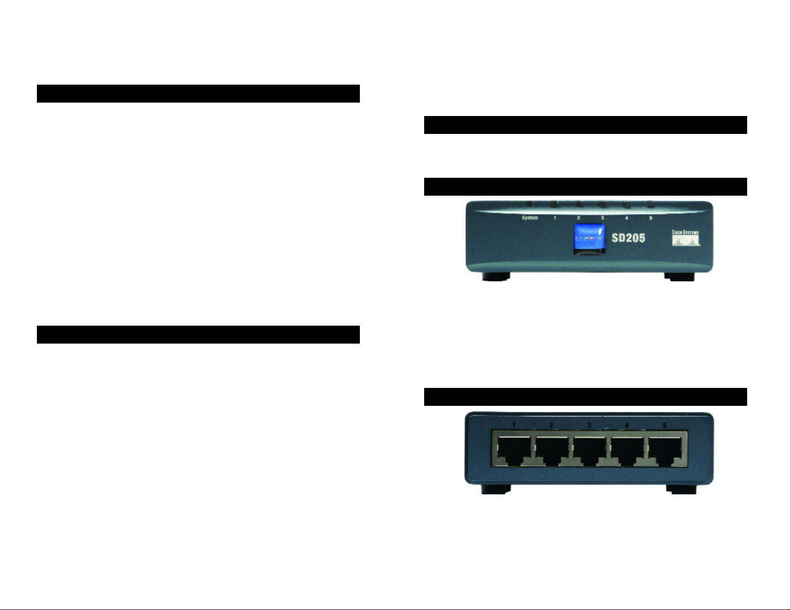
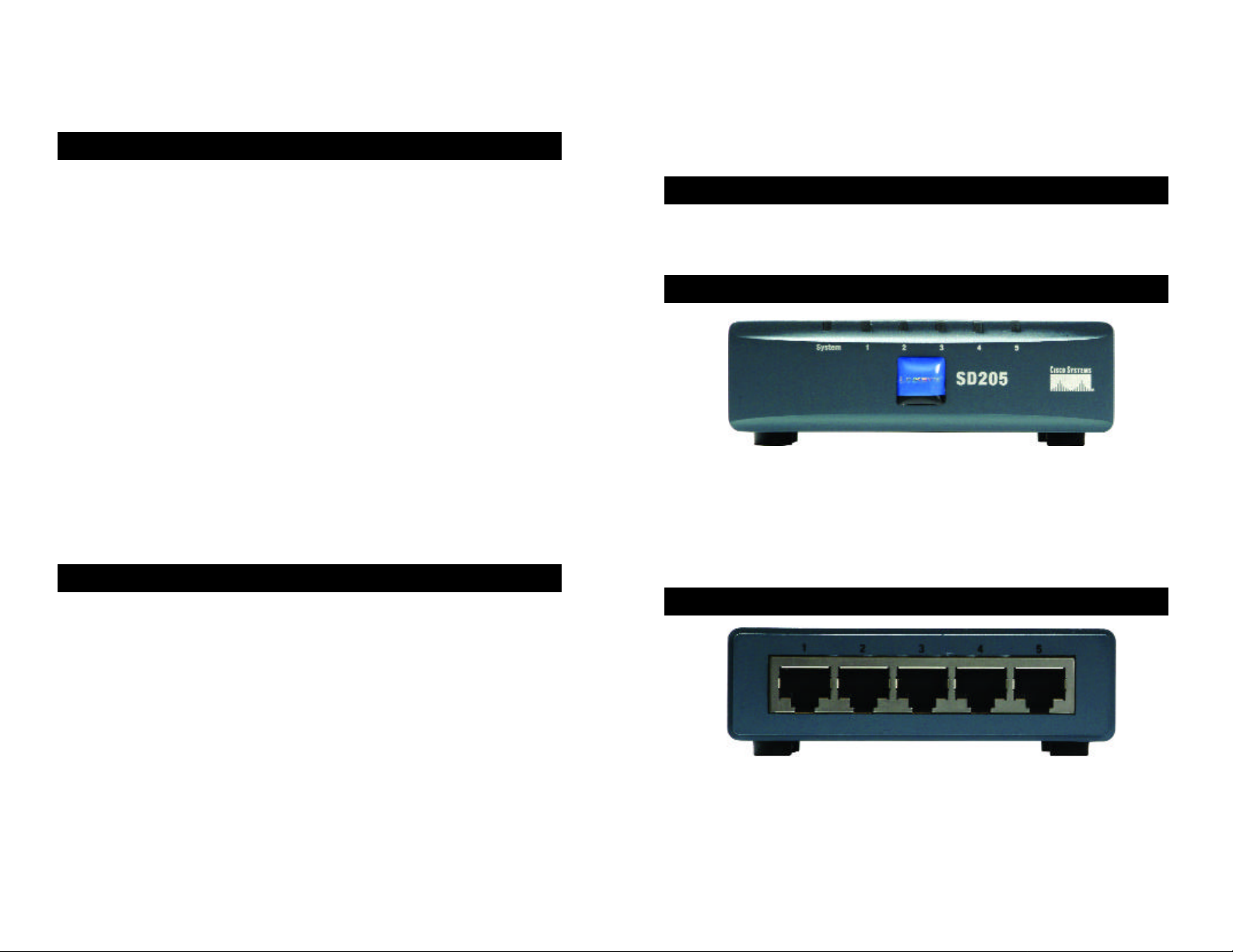
The 5-, 8-, and 16-Port 10/100 Switches differ in number of LEDs and ports.
Pictured here is the 5-Port 10/100 Switch; however, the other Switches are
similar in form.
Front Panel LEDs
The new, ultra-compact case design is sure to fit into your workgroup
environment. Let the Linksys 5-, 8-, or 16-Port 10/100 Switch kick your 10/100
network into high gear.
Features
• Ideal for Integrating Your 10BaseT and 100BaseTX Network Hardware
• 5, 8, or 16 10/100 Ports Provide Dedicated Bandwidth in Half- or FullDuplex Modes
• Each Port Supports Auto MDI/MDI-X Cable Detection
• Compatible with All Major Network Operating Systems
• Advanced Store-and-Forward Packet Switching Optimizes Data Transfers
• Auto Partitioning Protects PCs from Downed Network Lines
• Signal Regeneration Ensures Data Transfer Integrity
• Limited Lifetime Warranty
4
Figure 2-1
System Green. The System LED will light up when the Switch is
powered on.
1-5, 1-8, or 1-16 Green. Each LED will light up when there is a connection
made through its corresponding port. It will flash when there
is activity on its corresponding port.
Back and Side Panel Features
Figure 2-2
The network ports are located on the back panel of the Switch.
1-5, 1-8, or 1-16 These ports are connection points for PCs and other network
devices, such as additional switches.
5
Page 5
Chapter 3: Connecting the
10/100 Switch
Planning Your Network Layout
Overview
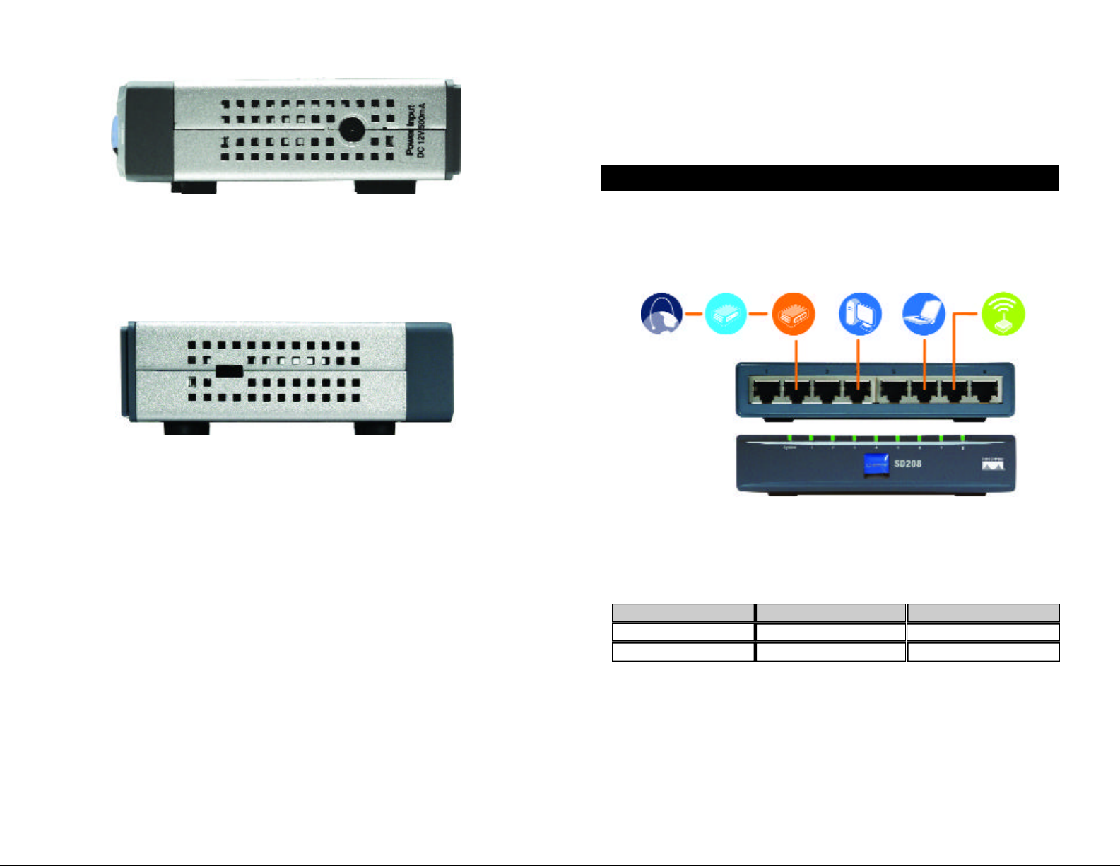
Figure 2-3
The power port is located on the side panel of the Switch (see Figure 2-3).
(power) The power port is where you will connect the included power
adapter.
Figure 2-4
The security slot is located on the other side panel (see Figure 2-4).
(security slot) The security slot is where you can attach a lock so the Switch
will be protected from theft.
This chapter will explain how to connect network devices to the Switch. For an
example of a typical network configuration, see the application diagram shown
in Figure 3-1.
Internet
When you connect your network devices, make sure you don’t exceed the
maximum cabling distances, which are listed in the following table:
Maximum Cabling Distances
Switch or Hub
*A hub refers to any type of 100Mbps hub, including regular hubs and stackable hubs. A 10Mbps hub
connected to another 10Mbps hub can span up to 100 meters (328 feet).
Cable/DSL
Modem
From
Switch
Broadband
Router Desktop PC Notebook Access Point
Figure 3-1
To
Switch or Hub*
Computer
Maximum Distance
1 00 meters (328 feet) 1
1 00 meters (328 feet) 1
6
7
Page 6
Connecting Network Devices
Placement Options
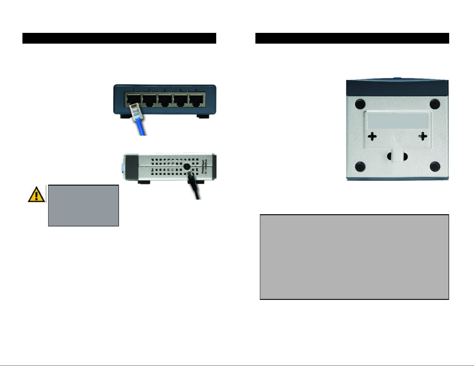
Follow these instructions for the 5-, 8-, and 16-Port 10/100 Switches (the 5-Port
10/100 Switch is shown in Figures 3-2 and 3-3).
1. Make sure all the devices you will connect to the Switch are powered off.
2. Connect a Category 5 Ethernet
network cable to one of the
numbered ports on the Switch.
3. Connect the other end to a PC
or other network device.
4. Repeat steps 2 and 3 to
connect additional devices.
Figure 3-2
5. Connect the supplied power
adapter to the power port on the
Switch’s side panel.
Note: Make sure you use the
power adapter included with
the Switch. Using a different
power adapter may result in
Figure 3-3
damage to the Switch.
6. Plug the other end of the adapter into a power outlet.
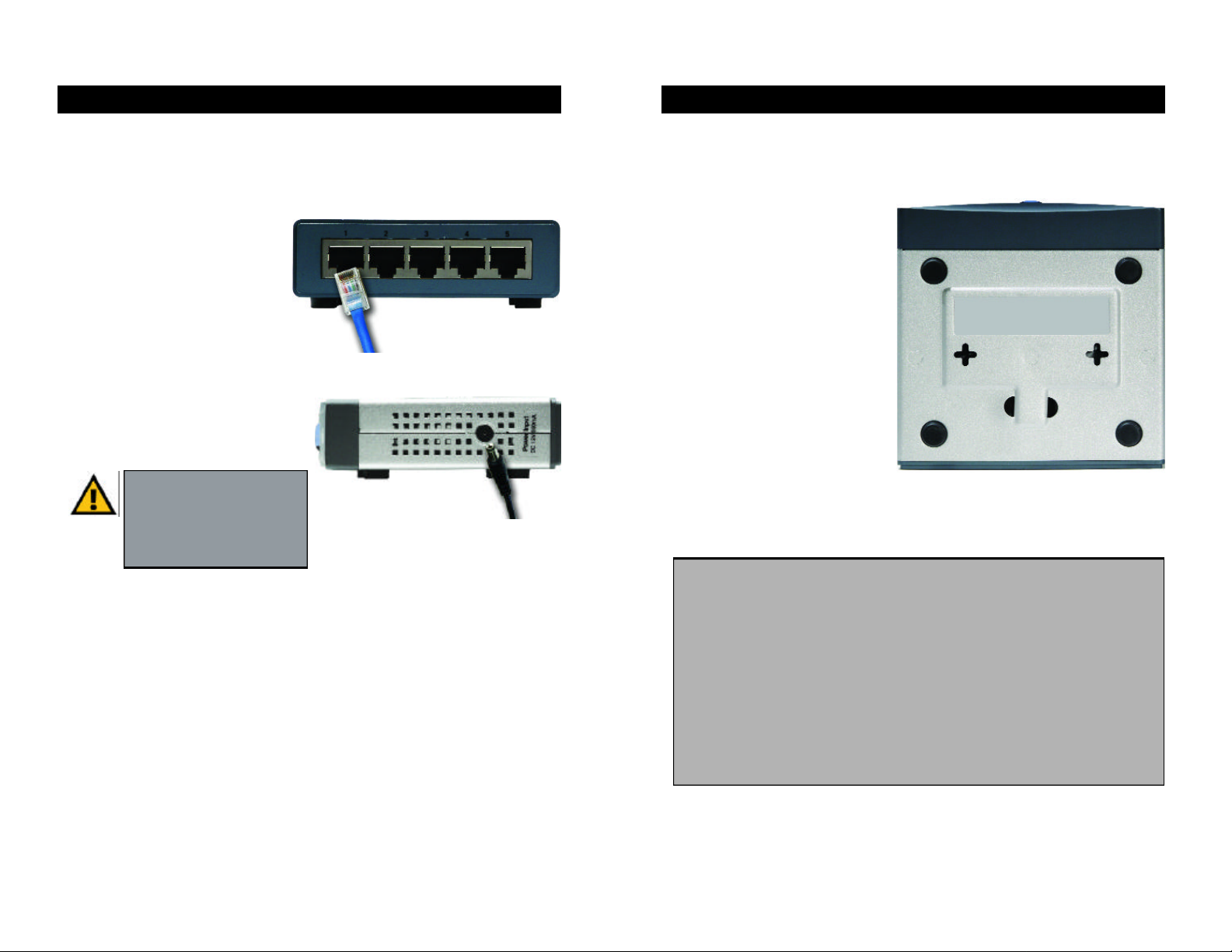
Set the Switch on its four rubber feet. For the 8- or 16-Port 10/100 Switch, you
can choose to hang it on a wall using its wall-mount slots. To use this option,
follow these instructions:
1. The wall-mount slots are two
crisscross slots on the Switch’s
bottom panel, as shown in
Figure 3-4. Attach two screws
to the wall, so that the Switch’s
wall-mount slots line up with
the two screws.
2. Maneuver the Switch so the
screws are inserted into the
two slots.
Congratulations!
The installation of the 10/100
Figure 3-4
Switch is complete.
For help with the installation or operation of the 10/100 Switch, contact
Linksys Technical Support at one of the phone numbers listed on the
Technical Support insert or one of the Internet addresses below:
7. Power on the devices connected to the Switch. Each active port’s
corresponding LED will light up on the Switch.
Proceed to the following section, “Placement Options.”
8
E-mail: Europe europe-support@linksys.com
United Kingdom &Ireland uks@linksys.com
Latin America latam-soporte@linksys.com
For unlisted regions or the most up-to-date contact information, please
visit the website below:
Website http://www.linksys.com/international
9
Page 7

Appendix A: Specifications
Model Number SD205 5-Port 10/100 Switch
SD208 8-Port 10/100 Switch
SD216 16-Port 10/100 Switch
Standards IEEE 802.3, IEEE 802.3u
Ports
SD205 5 RJ-45 10/100, Power
SD208 8 RJ-45 10/100, Power
SD216 16 RJ-45 10/100, Power
Cabling Type Category 5 Ethernet
LEDs
SD205 System, Port Status 1, 2, 3, 4, and 5
SD208 System, Port Status 1, 2, 3, 4, 5, 6, 7, and 8
SD216 System, Port Status 1, 2, 3, 4, 5, 6, 7, 8, 9, 10,
11, 12, 13, 14, 15, and 16
Environmental
Dimensions
SD205 93 mm x 30 mm x 90 mm
(3,66" x 1,18" x 3,54")
SD208 130 mm x 30 mm x 127 mm
(5,12" x 1,18" x 5,00")
SD216 130 mm x 40 mm x 127 mm
(5,12" x 1,57" x 5,00")
Unit Weight
SD205 0,23 kg (8 oz.)
SD208 0,43 kg (15 oz.)
SD216 0,54 kg (19 oz.)
Power
SD205 DC 12V, 500 mA
SD208 DC 12V, 500 mA
SD216 DC 12V, 1,5 A
Certifications FCC Class B, CE Mark
10
Operating Temp. 0ºC to 50ºC (32ºF to 122ºF)
Storage Temp. -40ºC to 70ºC (-40ºF to 158ºF)
Operating Humidity 20% to 95%, Non-Condensing
Storage Humidity 5% to 90%, Non-Condensing
11
Page 8

Appendix B: Warranty Information
LIMITED WARRANTY
Linksys warrants to the original end user purchaser (“You”) that, for a period of the
product’s lifetime, (the “Warranty Period”) Your Linksys product will be free of defects in
materials and workmanship under normal use. Your exclusive remedy and Linksys’s
entire liability under this warranty will be for Linksys at its option to repair or replace the
product or refund Your purchase price less any rebates.
If the product proves defective during the Warranty Period call Linksys Technical Support
in order to obtain a Return Authorization Number. BE SURE TO HAVE YOUR PROOF OF
PURCHASE ON HAND WHEN CALLING. When returning a product, mark the Return
Authorization Number clearly on the outside of the package and include a copy of your
original proof of purchase. RETURN REQUESTS CANNOT BE PROCESSED WITHOUT
PROOF OF PURCHASE. You are responsible for shipping defective products to Linksys.
Linksys pays for UPS Ground shipping from Linksys back to You only. Customers located
outside of the United States of America and Canada are responsible for all shipping and
handling charges.
ALL IMPLIED WARRANTIES AND CONDITIONS OF MERCHANTABILITY OR FITNESS
FOR A PARTICULAR PURPOSE ARE LIMITED TO THE DURATION OF THE WARRANTY
PERIOD. ALL OTHER EXPRESS OR IMPLIED CONDITIONS, REPRESENTATIONS AND
WARRANTIES, INCLUDING ANY IMPLIED WARRANTY OF NON-INFRINGEMENT, ARE
DISCLAIMED. Some jurisdictions do not allow limitations on how long an implied
warranty lasts, so the above limitation may not apply to You. This warranty gives You
specific legal rights, and You may also have other rights which vary by jurisdiction.
TO THE EXTENT NOT PROHIBITED BY LAW, IN NO EVENT WILL LINKSYS BE LIABLE
FOR ANY LOST DATA, REVENUE OR PROFIT, OR FOR SPECIAL, INDIRECT,
CONSEQUENTIAL, INCIDENTAL OR PUNITIVE DAMAGES, HOWEVER CAUSED
REGARDLESS OF THE THEORY OF LIABILITY, ARISING OUT OF OR RELATED TO THE
USE OF OR INABILITY TO USE THE PRODUCT, EVEN IF LINKSYS HAS BEEN ADVISED
OF THE POSSIBILITY OF SUCH DAMAGES. IN NO EVENT WILL LINKSYS' LIABILITY
EXCEED THE AMOUNT PAID BY YOU FOR THE PRODUCT.
The foregoing limitations will apply even if any warranty or remedy provided under this
Section fails of its essential purpose. Some jurisdictions do not allow the exclusion or
limitation of incidental or consequential damages, so the above limitation or exclusion
may not apply to You.
This Warranty is valid and may be processed only in the country of purchase.
Please direct all inquiries to: Linksys, P.O. Box 18558, Irvine, CA 92623.
12
13
Page 9

COPYRIGHT & MARQUES DE COMMERCE
Les spécifications peuvent être modifiées sans préavis. Copyright © 2003 Cisco
Systems, Inc. Tous droits réservés. Linksys est une marque déposée de Cisco Systems,
Inc. Les autres noms de marque et de produit sont des marques commerciales ou
déposées de leur détenteur respectif.
Déclaration de conformité CE (Europe)
Conformément aux directives 89/336/EEC sur la compatibilité électromagnétique,
73/23/EEC sur les basses tensions et 93/68/EEC sur les modifications, ce produit satisfait
aux exigences des normes suivantes :
• Norme EN55022 sur les émissions
• Norme EN55024 sur l’immunité
Table des matières
Chapitre 1 : Introduction 16
Commutateur 10/100 16
Caractéristiques techniques 16
Chapitre 2 : Présentation du
commutateur 10/100 17
Présentation 17
Voyants du panneau avant 17
Fonctionnalités des panneaux arrière et latéraux 17
Chapitre 3 : Branchement du
commutateur 10/100 19
Présentation 19
Branchement des périphériques réseau 20
Options d’emplacement 21
Annexe A : Spécifications 22
Conditions environnementales 23
Annexe B : Garantie 24
SD205_SD208_SD216-EU-UG-30606NC JL
14
15
Page 10
Chapitre 1 : Introduction
r
Commutateur 10/100
Remodelé dernièrement, ce commutateur 10/100 5, 8 ou 16 ports de Linksys
peut augmenter de façon significative le débit du trafic sur votre réseau. Un
commutateur tient le même rôle qu’un concentrateur au sein d’un réseau : il
relie les périphériques du réseau entre eux. Toutefois, au lieu d’agir
« naïvement » comme un concentrateur qui divise la bande passante du réseau
entre tous les périphériques connectés, un commutateur fournit un haut débit
réseau à chaque port. L’installation de ce commutateur 10/100 5, 8 ou 16 ports,
qui offre un excellent rapport coût/efficacité, peut potentiellement multiplier le
débit de votre réseau par 5, 8 ou 16 !
En outre, il permet également d’intégrer des périphériques Ethernet 10 Mbit/s
et Fast Ethernet 100 Mbit/s. Comme tous les ports peuvent négocier le débit et
détecter la liaison MDI/MDI-X automatiquement, vous n’avez plus à vous
préoccuper du type de câble. Chaque port négocie indépendamment le débit le
mieux adapté et le mode Full ou Semi Duplex pour une bande passante
atteignant 200 Mbit/s par port. La commutation rapide en différé empêche la
transmission des paquets endommagés sur le réseau.
Le nouveau boîtier ultra-compact ne peut que convenir à l’environnement de
votre groupe de travail. Permettez à votre réseau 10/100 de « passer la
cinquième» grâce au commutateur 10/100 5, 8 ou 16 ports de Linksys.
Caractéristiques techniques :
• Idéal pour intégrer vos périphériques réseau 10BaseT et 100BaseTX
• 5, 8 ou 16 ports 10/100 offrant une bande passante dédiée en mode Full et
Semi Duplex
• Chaque port prend en charge la détection automatique des câbles MDI/MDI-X
• Compatible avec tous les principaux systèmes d’exploitation de réseau
• La commutation avancée de paquets en différé optimise les transferts de donnée s
• Partitionnement automatique protégeant les PC des lignes réseau défectueuses
• La régénération du signal garantit l’intégrité du transfert des données
• Garantie à durée limitée
Chapitre 2 :Présentation du
commutateur 10/100
Planification de la configuration du réseau
Présentation
Les commutateurs 10/100 5, 8 et 16 ports ne possèdent pas le même nombre de
voyants et de ports. L’illustration ci-après représente un commutateur 10/100 5 ports.
Les autres commutateurs ont une forme similaire.
Voyants du panneau avant
Figure 2-1
System Vert. Le voyant System (Système) s’allume lorsque le
commutateur est mis sous tension.
1-5, 1-8 ou 1-16 Vert. Chaque voyant s’allume en cas de connexion via le port
correspondant. Il clignote lorsque le port correspondant est
utilisé.
Fonctionnalités des panneaux arrière et latéraux
Figure 2-2
16
Les ports réseau sont situés sur le panneau arrière du commutateur.
1-5, 1-8 ou 1-16 Ces ports représentent les points de connexion des PC et
autres périphériques réseau, comme les commutateurs
supplémentaires.
17
Page 11

Chapitre 3 :Branchement du
commutateur 10/100
Planification de la configuration du réseau
Présentation
Figure 2-3
Le port d’alimentation est situé sur le panneau latéral du commutateur (voir
figure 2-3).
(alimentation) Le port d’alimentation permet de brancher l’adaptateur
électrique fourni.
Figure 2-4
Le connecteur de sécurité est situé sur l’autre panneau latéral (voir figure 2-4).
(connecteur de sécurité) Le connecteur de sécurité permet de fixer un verrou
afin de protéger le commutateur contre le vol.
Ce chapitre décrit comment relier les périphériques réseau au commutateur.
La schématisation de l’application de la figure 3-1 est un exemple de
configuration réseau type.
Internet
Modem
câble/DSL
Routeur
haut débit
ordinateur
de bureau
Ordinateur
portable
Point d’accès
Figure 3-1
Lorsque vous branchez vos périphériques réseau, veillez à ne pas dépasser les
distances maximales de câblage énumérées dans le tableau suivant :
Distances maximales de câblage
De
Commutateur
Commutateur ou concentrateur
A
Commutateur ou concentrateur*
Ordinateur
Distance maximale
100 mètres 1
100 mètres 1
18
*Concentrateur signifie tout type de concentrateur 100 Mbit/s, y compris les concentrateurs directs et
les concentrateurs empilables. Deux concentrateurs 10 Mbit/s reliés entre eux peuvent couvrir une
distance maximale de 100 mètres.
19
Page 12
Branchement des périphériques réseau
Options d’emplacement
Procédez comme suit pour les commutateurs 10/100 5, 8 et 16 ports (les
figures 3-2 et 3-3 représentent le commutateur 10/100 5 ports).
1. Veillez à ce que tous les périphériques à connecter au commutateur soient
hors tension.
2. Reliez un câble réseau
Ethernet de catégorie 5 à l’un
des ports numérotés du
commutateur.
3. Reliez l’autre extrémité du
câble à un PC ou à un autre
périphérique réseau.
4. Répétez les étapes 2 et 3 pour
Figure 3-2
brancher d’autres périphériques.
5. Reliez l’adaptateur électrique
fourni au port d’alimentation situé
sur le panneau latéral du
commutateur.
Remarque : Veillez à utiliser
l’adaptateur électrique fourni
avec le commutateur.
L’utilisation d’un autre
Figure 3-3
adaptateur électrique pourrait
endommager le commutateur.
6. Branchez l’autre extrémité de l’adaptateur sur une prise d’alimentation.
Posez le commutateur sur ses quatre pieds en caoutchouc. Si vous le souhaitez,
vous pouvez monter le commutateur 10/100 8 ou 16 ports au mur au moyen des
orifices de montage mural. Pour ce faire, procédez comme suit :
1. Les orifices de montage mural
sont deux orifices en forme de
croix situés sur le panneau
inférieur du commutateur
comme illustré dans la figure
3-4. Fixez deux vis au mur de
sorte de pouvoir les aligner
avec les orifices de montage
mural du commutateur.
2. Manoeuvrez le commutateur de
sorte d’insérer les vis dans les
deux orifices.
Félicitations !
L’installation du
commutateur 10/100 est
Figure 3-4
terminée.
Pour toute assistance relative à l’installation ou au fonctionnement du
commutateur 10/100, veuillez contacter le support technique de Linksys à
l’un des numéros de téléphone mentionnés dans l’encart Support technique
ou en envoyant un message à l’une des adresses Internet ci-après :
7. Mettez sous tension les périphériques connectés au commutateur. Le voyant
correspondant à chaque port actif s’allume sur le commutateur.
E-mail : Europe europe-support@linksys.com
Royaume-Uni et
Irlande uks@linksys.com
Amérique latine latam-soporte@linksys.com
Passez à la section « Options d’emplacement ».
Si votre région n’est pas mentionnée ou si vous souhaitez mettre à jour les
données relatives au contact, veuillez visiter le site Web ci-après :
Site Web http://www.linksys.com/international
20 21
Page 13

Annexe A : Spécifications
Référence du modèle SD205 Commutateur 10/100 5 ports
SD208 Commutateur 10/100 8 ports
SD216 Commutateur 10/100 16 ports
Normes IEEE 802.3, IEEE 802.3u
Ports
SD205 5 ports RJ-45 10/100, alimentation
SD208 8 ports RJ-45 10/100, alimentation
SD216 16 ports RJ-45 10/100, alimentation
Type de câblage Ethernet catégorie 5
Conditions environnementales
Dimensions
SD205 93 x 30 x 90 mm
(3,66 x 1,18 x 3,54")
SD208 130 x 30 x 127 mm
(5,12 x 1,18 x 5,00")
SD216 130 x 40 x 127 mm
(5,12 x 1,57 x 5,00")
Poids
SD205 0,23kg
SD208 0,43kg
SD216 0,54kg
Voyants
SD205 Système, état des ports 1, 2, 3, 4 et 5
SD208 Système, état des ports 1, 2, 3, 4, 5, 6, 7 et 8
SD216 Système, état des ports 1, 2, 3, 4, 5,
6, 7, 8, 9, 10,11, 12, 13, 14, 15 et 16
Alimentation
SD205 CC 12V, 500 mA
SD208 CC 12V, 500 mA
SD216 CC 12V, 1,5A
Certifications FCC Classe B, Marquage CE
Température en
fonctionnement 0ºC à 50ºC
Température
de stockage -40ºC à 70ºC
Humidité en
fonctionnement 20% à 95%, non condensée
Humidité de
stockage 5% à 90%, non condensée
22 23
Page 14

Annexe B :Garantie
GARANTIE LIMITEE
Linksys garantit à l’acheteur/utilisateur final (« Vous ») que, pour la période relative à la
durée de vie du produit (la « Période de garantie»), votre produit Linksys sera exempt
de défaut de pièce et de main d’oeuvre dans le cadre d’une utilisation normale. Votre
unique recours et la responsabilité totale de Linksys dans le cadre de cette garantie se
résument à la possibilité pour Linksys, à son propre grès, de faire réparer ou remplacer
le produit ou de vous rembourser son prix d’achat moins toutes remises.
Si ce produit devait s’avérer défectueux pendant cette période de garantie, contactez le
support technique de Linksys pour obtenir un numéro d’autorisation de retour.
N’OUBLIEZ PAS DE CONSERVER VOTRE PREUVE D’ACHAT A PORTEE DE MAIN
LORSQUE VOUS TELEPHONEZ. Lorsque vous retournez un produit, indiquez clairement
le numéro d’autorisation de retour à l’extérieur de l’emballage et n’oubliez pas de joindre
une copie de l’original de votre preuve d’achat. IL EST IMPOSSIBLE DE TRAITER LES
DEMANDES DE RETOUR EN L’ABSENCE DE LA PREUVE D’ACHAT. Le retour des
produits défectueux à Linksys relève de votre responsabilité. Linksys prend uniquement
en charge les envois via UPS Ground de Linksys chez Vous. Les frais d’envoi restent à
la charge des clients implantés en dehors des Etats-Unis et du Canada.
TOUTES LES GARANTIES IMPLICITES ET CONDITIONS DE VALEUR MARCHANDE OU
D’ADEQUATION A UN USAGE PARTICULIER SONT LIMITEES A LA DUREE DE LA
PERIODE DE GARANTIE. TOUTES LES AUTRES CONDITIONS, DECLARATIONS ET
GARANTIES IMPLICITES OU EXPLICITES, Y COMPRIS TOUTE GARANTIE IMPLICITE DE
NON CONTREFACON SONT DEMENTIES. Certaines juridictions n’autorisent pas les
restrictions relatives à la durée d’une garantie implicite. Par conséquent, la restriction
susmentionnée peut ne pas s’appliquer dans votre cas. Cette garantie vous accorde des
droits spécifiques. Vous pouvez avoir d’autres droits qui varient en fonction des juridictions.
CONFORMEMENT A LA LOI ET INDEPENDAMMENT DE LA THEORIE SUR LES
RESPONSABILITES, LINKSYS NE POURRA EN AUCUN CAS ETRE TENUE
RESPONSABLE DES PERTES DE DONNEES, DE CHIFFRE D’AFFAIRES OU DE
BENEFICE OU DES DOMMAGES SPECIAUX, INDIRECTS, CONSECUTIFS,
ACCIDENTELS OU DISSUASIFS, LIE OU NON LIE A L’UTILISATION OU A L’INCAPACITE
A UTILISER LE PRODUIT, MEME SI LINKSYS A ETE AVERTI DE LA POSSIBILITE DE
TELS DOMMAGES. EN AUCUN CAS LA RESPONSABILITE DE LINKSYS NE POURRA
EXCEDER LE MONTANT QUE VOUS AVEZ PAYE POUR ACQUERIR LE PRODUIT.
Les restrictions susmentionnées s’appliqueront même si toute garantie ou tout recours
indiqué dans cette section ne remplit pas sa fonction principale. Certaines juridictions
n’autorisent pas l’exclusion ou la restriction des dommages accidentels et consécutifs.
Par conséquent, la restriction ou l’exclusion susmentionnée peut ne pas s’appliquer
dans votre cas.
Cette garantie est valide et peut ne s’appliquer que dans le pays d’acquisition du produit.
Veuillez envoyer toutes vos demandes de renseignement à l’adresse suivante : Linksys,
24 25
Page 15

COPYRIGHT & MARKEN
Technische Änderungen vorbehalten. Copyright © 2003 Cisco Systems, Inc. Alle Rechte
vorbehalten. Linksys ist eine eingetragene Marke von Cisco Systems, Inc. Andere
Handelsmarken und Produktnamen sind Marken bzw. eingetragene Marken der
jeweiligen Inhaber.
EU-KONFORMITÄTSERKLÄRUNG (EUROPA)
In Einklang mit der EWG-Richtlinie 89/336/EWG, der Niederspannungsrichtlinie
73/23/EWG sowie dem Merkblatt zur EU-Richtlinie 93/68/EWG entspricht dieses Produkt
den folgenden Standards:
• EN55022 Emission
• EN55024 Immunität
Inhalt
Kapitel 1: Einführung 28
Der 10/100 Switch 28
Funktionen 28
Kapitel 2: Beschreibung des 10/100 Switch 29
Übersicht 29
Lämpchen an der Vorderseite 29
Ports an der Rückseite und an den Seitenwänden 29
Kapitel 3: Anschließen des 10/100 Switch 31
Übersicht 31
Anschließen von Netzwerkgeräten 32
Standortoptionen 33
Anhang A: Spezifikationen 34
Umgebungsbedingungen 35
Anhang B: Garantieinformationen 36
SD205_SD208_SD216-EU-UG-30606NC JL
26 27
Page 16

Kapitel 1: Einführung
r
Der 10/100 Switch
Der neu aufgelegte Linksys 5-, 8- oder 16-Port 10/100 Switch kann die
Übertragungsgeschwindigkeiten in Ihrem Netzwerk beträchtlich
beschleunigen. Ein Switch hat im Netzwerk dieselbe Funktion wie ein Hub: er
ist das Bindeglied zwischen den Netzwerkgeräten. Im Gegensatz zu einem
einfachen Hub, der die Bandbreite des Netzwerks zwischen allen
angeschlossenen Geräten verteilt, erzielt ein Switch jedoch an jedem Port die
volle Netzwerkgeschwindigkeit. Durch die Installation dieses kosteneffektiven
5-, 8- oder 16-Port 10/100 Switch können Sie Ihre Netzwerkgeschwindigkeit
unter Umständen um das Fünffache, Achtfache oder Sechzehnfache steigern!
Darüber hinaus bietet er eine optimale Möglichkeit zur Integration von
10 MBit/s-Ethernet- und 100 MBit/s-Fast Ethernet-Geräten. Alle Ports
verfügen über Funktionen zur automatischen Anpassung der
Übertragungsgeschwindigkeit sowie automatische MDI/MDI-X-CrossoverErkennung, sodass Sie sich keine Gedanken über den Kabeltyp machen müssen.
Die Anpassung für optimale Geschwindigkeit und Halb- bzw. Vollduplexmodus
erfolgt individuell für jeden Port für bis zu 200 MBit/s Bandbreite pro Port.
Schnelles Switching mit Speicher- und Weiterleitungsfunktionen verhindert,
dass beschädigte Pakete in das Netzwerk weitergeleitet werden.
Kapitel 2: Beschreibung des
10/100 Switch
Festlegen des Netzwerk-Layouts
Übersicht
Die 5-, 8- und 16-Port 10/100 Switches verfügen über eine unterschiedliche
Anzahl an Lämpchen und Ports. Die folgenden Abbildungen zeigen den 5-Port
10/100 Switch. Die anderen Switches sind jedoch ähnlich aufgebaut.
Lämpchen an der Vorderseite
Abbildung 2-1
System Grün. Das System-Lämpchen leuchtet auf, wenn der Switch
eingeschaltet wird.
Das neue hochgradig kompakte Format fügt sich problemlos in Ihre
Arbeitsgruppenumgebung ein. Bringen Sie Ihr 10/100-Netzwerk mit dem
neuen Linksys 5-, 8- oder 16-Port 10/100 Switch auf Trab.
Funktionen
• Ideal zur Integration Ihrer 10BaseT- und 100BaseTX-Netzwerk-Hardware
• Fünf, acht oder sechzehn 10/100 Ports sorgen für dedizierte Bandbreite im
Halb- oder Vollduplex-Modus
• An jedem Port wird die automatische MDI/MDI-X-Kabelerkennung
unterstützt
• Mit allen gängigen Netzwerkbetriebssystemen kompatibel
• Erweitertes Paket-Switching mit Speicher- und Weiterleitungsfunktionen
sorgt für optimierte Datenübertragung
• Automatische Partitionierung schützt den PC bei Zusammenbrüchen von
Netzwerkleitungen
• Signalregeneration gewährleistet Integrität bei der Datenübertragung
• Eingeschränkte Garantie
28 29
1-5, 1-8, 1-16 Grün. Die einzelnen Lämpchen leuchten auf, wenn eine
Verbindung über den zugehörigen Port hergestellt wird. Sie
blinken, wenn Aktivitäten am zugehörigen Port stattfinden.
Ports an der Rückseite und an den Seitenwänden
Abbildung 2-2
Die Netzwerk-Ports befinden sich an der Rückseite des Switch.
1-5, 1-8, 1-16 Diese Ports bilden die Verbindungspunkte für PCs und andere
Netzwerkgeräte, wie beispielsweise zusätzliche Switches.
Page 17

Kapitel 3: Anschließen des
10/100 Switch
Festlegen des Netzwerk-Layouts
Übersicht
Abbildung 2-3
Der Netzstrom-Port befindet sich an der Seitenwand des Switch (siehe
Abbildung 2-3).
(Netzstrom) Schließen Sie den im Lieferumfang enthaltenen
Netzstromadapter an den Netzstrom-Port an.
Abbildung 2-4
Der Sicherheitssteckplatz befindet sich an der anderen Seitenwand (siehe
Abbildung 2-4).
(Sicherheitssteckplatz) Am Sicherheitssteckplatz können Sie ein Schloss
anbringen, um den Switch gegen Diebstahl zu
schützen.
In diesem Kapitel wird erklärt, wie Sie Netzwerkgeräte an den Switch
anschließen. Das Anwendungsbeispiel in Abbildung 3-1 zeigt eine typische
Netzwerkkonfiguration.
Internet
Achten Sie beim Anschließen der Netzwerkgeräte darauf, dass die in der
folgenden Tabelle angegebenen maximalen Kabellängen nicht überschritten
werden:
Maximale Kabellängen
Switch oder Hub
Kabel-/DSL-
Modem
Vom
Switch
Broadband-
Router
Abbildung 3-1
Zum
Switch oder Hub*
Computer
Desktop-
PC Notebook Access Point
Maximaler Abstand
1 00 Meter 1
1 00 Meter 1
*Als Hub werden hier alle Arten von 100-MBit/s-Hubs bezeichnet (einschließlich regulärer Hubs und
stapelfähiger Hubs). Wird an einen 10-MBit/s-Hub ein weiterer 10-MBit/s-Hub angeschlossen, können
bis zu 100 Meter überbrückt werden.
30 31
Page 18

Anschließen von Netzwerkgeräten
Standortoptionen
Fahren Sie mit den folgenden Anweisungen für 5-, 8- und 16-Port 10/100 Switches
fort (in Abbildung 3-2 und 3-3 wird der 5-Port 10/100 Switch dargestellt).
1. Vergewissern Sie sich, dass alle an den Switch anzuschließenden Geräte
ausgeschaltet sind.
2. Schließen Sie ein EthernetNetzwerkkabel der Kategorie 5
an einen der nummeriert Ports
am Switch an.
3. Schließen Sie das andere Ende
an einen PC oder an ein
anderes Netzwerkgerät an.
Abbildung 3-2
4. Wiederholen Sie die Schritte 2 und 3, um weitere Geräte anzuschließen.
5. Schließen Sie den im Lieferumfang
enthaltenen Netzstromadapter an
den Netzstrom-Port an der
Seitenwand des Switch an.
Hinweis: Verwenden Sie nur
den im Lieferumfang des
Switch enthaltenen
Netzstromadapter. Bei
Abbildung 3-3
Verwendung eines anderen
Netzstromadapters kann der
Switch beschädigt werden.
6. Schließen Sie das andere Ende des Adapters an eine Netzsteckdose an.
7. Schalten Sie die an den Switch angeschlossenen Geräte ein. Die Lämpchen
der aktiven Ports leuchten am Switch auf.
Stellen Sie den Switch auf den vier Gummifüßen auf. Beim 8- bzw. 16-Port
10/100 Switch ist auch eine Wandmontage mithilfe der entsprechenden Löcher
möglich. Fahren Sie in diesem Fall mit den folgenden Anweisungen fort:
1. Bei den Löchern für die
Wandmontage handelt es sich
um zwei sich kreuzende
Schlitze auf der Unterseite des
Switch (siehe Abbildung 3-4).
Bringen Sie zwei Schrauben an
der Wand an. Achten Sie
darauf, dass deren Abstand
dem Abstand zwischen den
Kreuzlöchern am Switch
entspricht.
2. Schieben Sie den Switch so hin
und her, dass die Schrauben in
die Kreuzlöcher eingreifen.
Abbildung 3-4
Geschafft!
Die Installation des 10/100
Switch ist abgeschlossen.
Hilfestellung zur Installation oder Verwendung des 10/100 Switch erhalten
Sie beim technischen Kundendienst von Linksys unter einer der in der
Technischen Support-Beilage aufgelisteten Telefonnummern bzw. unter
einer der im Folgenden aufgelisteten Internet-Adressen:
E-Mail:Europa europe-support@linksys.com
Großbritannien und Irland uks@linksys.com
Lateinamerika latam-soporte@linksys.com
Fahren Sie mit dem folgenden Abschnitt „Standortoptionen“ fort.
Informationen zu nicht aufgelisteten Regionen und die aktuellsten
Kontaktinformationen finden Sie auf folgender Website:
Website http://www.linksys.com/international
32 33
Page 19

Anhang A: Spezifikationen
Modellnummer SD205 5-Port 10/100 Switch
SD208 8-Port 10/100 Switch
SD216 16-Port 10/100 Switch
Umgebungsbedingungen
Abmessungen
SD205 93 mm x 30 mm x 90 mm
SD208 130 mm x 30 mm x 127 mm
SD216 130 mm x 40 mm x 127 mm
Standards IEEE 802.3, IEEE 802.3u
Ports
SD205 5 RJ-45 10/100, Netzstrom
SD208 8 RJ-45 10/100, Netzstrom
SD216 16 RJ-45 10/100 , Netzstrom
Kabeltyp Ethernet Kategorie 5
Lämpchen
SD205 System, Port-Status 1, 2, 3, 4 und 5
SD208 System, Port-Status 1, 2, 3, 4, 5, 6, 7 und 8
SD216 System, Port-Status 1, 2, 3, 4, 5, 6, 7, 8, 9, 10,
11, 12, 13, 14, 15 und 16
Gerätegewicht
SD205 0,23 kg
SD208 0,43 kg
SD216 0,54 kg
Netzstrom
SD205 12 V GS, 500 mA
SD208 12 V GS, 500 mA
SD216 12 V GS, 1,5 A
Zertifizierungen FCC Class B, CE-Markierung
Betriebstemperatur 0 ºC bis 50 ºC
Lagertemperatur -40 ºC bis 70 ºC
Betriebsfeuchtigkeit 20 % bis 95 %, nicht kondensierend
Lagerfeuchtigkeit 5 % bis 90 %, nicht kondensierend
34 35
Page 20

Anhang B:Garantieinformationen
EINGESCHRÄNKTE GEWÄHRLEISTUNG
Linksys sichert dem ursprünglichen Endbenutzer, der das Produkt erwirbt, („Ihnen“) für
einen bestimmten Zeitraum der Lebensdauer des Produkts (die „Gewährleistungsfrist“)
zu, dass dieses Linksys-Produkt bei normaler Verwendung keine Material- oder
Verarbeitungsfehler aufweist. Im Rahmen dieser Gewährleistung beschränken sich Ihre
Rechtsmittel und der Haftungsumfang von Linksys wie folgt: Linksys kann nach eigener
Wahl das Produkt reparieren oder austauschen oder Ihnen den Kaufpreis abzüglich
etwaiger Nachlässe zurückerstatten.
Sollte sich das Produkt während der Gewährleistungsfrist als fehlerhaft erweisen, wenden
Sie sich an den technischen Kundendienst von Linksys, um eine sog. Return Authorization
Number (Nummer zur berechtigten Rücksendung) zu erhalten. WENN SIE SICH AN DEN
TECHNISCHEN KUNDENDIENST WENDEN, SOLLTEN SIE IHREN KAUFBELEG ZUR
HAND HABEN. Markieren Sie bei Rücksendung des Produkts die Nummer zur
berechtigten Rücksendung deutlich auf der Außenseite der Verpackung, und legen Sie
eine Kopie des Kaufbelegs bei. RÜCKSENDEANFRAGEN KÖNNEN NICHT OHNE DEN
KAUFBELEG BEARBEITET WERDEN. Der Versand fehlerhafter Produkte an Linksys
unterliegt Ihrer Verantwortung. Linksys kommt nur für Versandkosten von Linksys zu Ihrem
Standort per UPS auf dem Landweg auf. Bei Kunden außerhalb der USA und Kanada sind
sämtliche Versand- und Abfertigungskosten durch die Kunden selbst zu tragen.
ALLE GEWÄHRLEISTUNGEN UND BEDINGUNGEN STILLSCHWEIGENDER ART
HINSICHTLICH DER MARKTÜBLICHEN QUALITÄT ODER DER EIGNUNG FÜR EINEN
BESTIMMTEN ZWECK SIND AUF DIE DAUER DER GEWÄHRLEISTUNGSFRIST
BESCHRÄNKT. JEGLICHE WEITEREN BEDINGUNGEN, ZUSICHERUNGEN UND
GEWÄHRLEISTUNGEN SOWOHL AUSDRÜCKLICHER ALS AUCH
STILLSCHWEIGENDER ART, EINSCHLIESSLICH JEGLICHER STILLSCHWEIGENDER
GEWÄHRLEISTUNG DER NICHTVERLETZUNG, WERDEN AUSGESCHLOSSEN. Einige
Gerichtsbarkeiten gestatten keine Beschränkungen hinsichtlich der Gültigkeitsdauer
einer stillschweigenden Gewährleistung; die oben genannte Beschränkung findet daher
unter Umständen bei Ihnen keine Anwendung. Die vorliegende Gewährleistung sichert
Ihnen bestimmte gesetzlich verankerte Rechte zu. Darüber hinaus stehen Ihnen je nach
Gerichtsbarkeit unter Umständen weitere Rechte zu.
SOWEIT NICHT GESETZLICH UNTERSAGT, SCHLIESST LINKSYS JEGLICHE HAFTUNG
FÜR VERLOREN GEGANGENE DATEN, ENTGANGENE EINNAHMEN, ENTGANGENE
GEWINNE ODER SONSTIGE SCHÄDEN BESONDERER, INDIREKTER, MITTELBARER,
BEILÄUFIGER ODER BESTRAFENDER ART AUS, DIE SICH AUS DER VERWENDUNG
BZW. DER NICHTVERWENDBARKEIT PRODUKTS ERGEBEN ODER MIT DIESER
ZUSAMMENHÄNGEN, UNABHÄNGIG VON DER URSACHE UND DER
HAFTUNGSTHEORIE, AUCH WENN LINKSYS ÜBER DIE MÖGLICHKEIT SOLCHER
SCHÄDEN INFORMIERT WURDE. DIE HAFTUNG VON LINKSYS IST STETS AUF DEN
FÜR DAS PRODUKT GEZAHLTEN BETRAG BESCHRÄNKT.
Die oben genannten Beschränkungen kommen auch dann zur Anwendung, wenn eine
in diesem Abschnitt aufgeführte Gewährleistung oder Zusicherung ihren wesentlichen
Zweck verfehlt. Einige Gerichtsbarkeiten gestatten keinen Ausschluss bzw. keine
Beschränkungen von beiläufigen oder mittelbaren Schäden; die oben genannte
Beschränkung oder der oben genannte Ausschluss findet daher unter Umständen bei
Ihnen keine Anwendung.
Die vorliegende Gewährleistung ist nur in dem Land gültig bzw. kann dort verarbeitet
werden, in dem das Produkt erworben wurde.
Richten Sie alle Anfragen direkt an: Linksys, P.O. Box 18558, Irvine, CA 92623, USA.
36 37
Page 21

COPYRIGHT E MARCHI
Le specifiche sono soggette a modifiche senza preavviso. Copyright © 2003 Cisco
Systems, Inc. Tutti i diritti riservati. Linksys è un marchio registrato di Cisco Systems, Inc.
Altri marchi e nomi di prodotti sono marchi o marchi registrati dei rispettivi proprietari.
Dichiarazione di conformità CE (Europa)
Questo prodotto è conforme alle specifiche tecniche elencate di seguito, in osservanza
alle clausole della direttiva EMC 89/336/EEC, della direttiva sulla bassa tensione
73/23/EEC e della direttiva sugli emendamenti 93/68/EEC:
• EN55022 - Emissioni
• EN55024 - Immunità
Indice
Capitolo 1: Introduzione 40
Switch 10/100 40
Funzioni 40
Capitolo 2: Introduzione allo switch 10/100 41
Informazioni generali 41
LED del pannello anteriore 41
Funzioni dei pannelli posteriore e laterale 41
Capitolo 3: Collegamento dello switch 10/100 43
Informazioni generali 43
Collegamento dei dispositivi di rete 44
Opzioni di posizionamento 45
Appendice A: Specifiche 46
Specifiche ambientali 47
Appendice B: Informazioni sulla garanzia 48
SD205_SD208_SD216-EU-UG-30606NC JL
38 39
Page 22

Capitolo 1: Introduzione
r
Switch 10/100
Questo switch 10/100 a 5, 8 o 16 porte di Linksys, che vanta una recente
riprogettazione, è in grado di aumentare notevolmente la velocità del traffico di
rete. La funzione di uno switch è uguale a quella di un hub in un ambiente di
rete, ovvero unire i dispositivi di una rete. Tuttavia, diversamente da un
semplice hub che divide la larghezza di banda della rete tra tutti i dispositivi
collegati, lo switch fornisce l’intera velocità di rete ad ogni porta.
L’installazione di questo conveniente switch 10/100 a 5, 8 o 16 porte può
aumentare potenzialmente la velocità di rete di cinque, otto o sedici volte.
Inoltre, rappresenta il modo migliore di integrare i dispositivi Ethernet
10 Mbps e Fast Ethernet 100 Mbps. Tutte le porte supportano la negoziazione
automatica della velocità e dispongono del rilevamento incrociato MDI/MDI -X
automatico, evitando in questo modo la necessità di controllare il tipo di cavo.
Ogni porta negozia in modo autonomo la migliore velocità e la modalità half
duplex o full duplex, fino a 200 Mbps di larghezza di banda per porta. Una
commutazione veloce a memorizzazione e ritrasmissione evita che i pacchetti
danneggiati avanzino nella rete.
Il nuovo design estremamente compatto garantisce un adattamento a qualsiasi
ambiente di lavoro. Con lo switch 10/100 a 5, 8 o 16 porte di Linksys la rete
10/100 avrà una marcia in più!
Funzioni
• Ideale per l’integrazione dell’hardware di rete 10BaseT e 100BaseTX
• Le 5, 8 o 16 porte 10/100 forniscono una larghezza di banda dedicata nelle
modalità half duplex o full duplex
• Ogni porta supporta il rilevamento automatico dei cavi MDI/MDI-X
• Compatibile con tutti i principali sistemi operativi di rete
• La commutazione avanzata dei pacchetti a memorizzazione e ritrasmissione
ottimizza i trasferimenti dei dati
• La partizione automatica protegge i PC dalle linee di rete disattivate
• La rigenerazione dei segnali assicura l’integrità del trasferimento di dati
• Garanzia limitata
Capitolo 2: Introduzione allo switch
10/100
Pianificazione della disposizione di rete
Informazioni generali
Gli switch 10/100 a 5, 8 e 16 porte differiscono per numero di LED e porte. Le
seguenti illustrazioni mostrano lo switch 10/100 a 5 porte; tuttavia, l’aspetto
degli altri switch è simile.
LED del pannello anteriore
Figura 2-1
Sistema Verde. Il LED di sistema si illumina quando lo switch è
acceso.
1-5, 1-8 o 1-16 Verde. Ogni LED si illumina quando viene stabilito un
collegamento attraverso la porta corrispondente, lampeggia
quando si registra attività sulla porta corrispondente.
Funzioni dei pannelli posteriore e laterale
Figura 2-2
Le porte di rete si trovano sul pannello posteriore dello switch.
1-5, 1-8 o 1-16 Queste porte rappresentano dei punti di collegamento per PC
e altri dispositivi di rete, ad esempio altri switch.
40 41
Page 23

Capitolo 3: Collegamento dello
switch 10/100
Pianificazione della disposizione di rete
Informazioni generali
Figura 2-3
La porta di alimentazione si trova sul pannello laterale dello switch (vedere la
Figura 2-3).
(alimentazione) La porta di alimentazione consente di collegare
l’adattatore di corrente in dotazione.
Figura 2-4
Lo slot di sicurezza si trova sull’altro pannello laterale (vedere la Figura 2-4).
(slot di sicurezza) Lo slot di sicurezza consente di inserire un lucchetto in
modo che lo switch sia protetto contro eventuali furti.
Questo capitolo descrive come collegare i dispositivi di rete allo switch. Come
esempio di una tipica configurazione di rete, vedere lo schema di applicazione
mostrato nella Figura 3-1.
Internet
Quando si collegano i dispositivi di rete, assicurarsi di non superare le distanze
massime consentite per i cavi, elencate nella seguente tabella:
Distanze massime dei cavi
Switch o hub
Modem via
cavo/DSL
Da
Switch
Router a
banda larga PC desktop Notebook Access Point
Figura 3-1
A
Switch o hub*
Computer
Distanza massima
1 00 metri 1
1 00 metri 1
*Per hub si intende qualsiasi tipo di hub 100 Mbps, compresi gli hub nomali e quelli impilabili. Un hub
10 Mbps collegato a un altro hub 10 Mbps può espandersi fino a 100 metri.
42 43
Page 24

Collegamento dei dispositivi di rete
Opzioni di posizionamento
Seguire le istruzioni per gli switch 10/100 a 5, 8 e 16 porte (lo switch 10/100 a
5 porte viene mostrato nelle Figure 3-2 e 3-3).
1. Assicurarsi che tutti i dispositivi da collegare allo switch siano spenti.
2. Collegare il cavo di rete
Ethernet di Categoria 5 a una
delle porte numerate sullo
switch.
3. Collegare l’altra estremità a un
PC o un altro dispositivo di
rete.
Figura 3-2
4. Ripetere i punti 2 e 3 per collegare altri dispositivi.
5. Collegare l’adattatore di corrente
in dotazione alla porta di
alimentazione sul pannello laterale
dello switch.
Nota: utilizzare l’adattatore
di corrente fornito con lo
switch. L’uso di un diverso
Figura 3-3
adattatore di corrente può
provocare danni allo switch.
6. Collegare l’altra estremità dell’adattatore in una presa di alimentazione.
Posizionare lo switch sui quattro piedini gommati. Gli switch 10/100 a 8 o
16 porte possono essere attaccati al muro grazie ai relativi alloggiamenti di
montaggio. Per utilizzare questa opzione, attenersi alle seguenti istruzioni.
1. Gli alloggiamenti per il
montaggio a muro sono due
fessure a croce sul pannello
inferiore dello switch, come
mostrato nella Figura 3-4.
Inserire due viti al muro, in
modo che gli alloggiamenti per
il montaggio a muro dello
switch siano allineati alle due
viti.
2. Spostare lo switch in modo da
inserire le viti nei due
alloggiamenti.
Congratulazioni.
Figura 3-4
L’installazione dello switch
10/100 è completata.
Per ulteriori informazioni sull’installazione o il funzionamento dello switch
10/100, contattare l’Assistenza tecnica di Linksys a uno dei numeri di
telefono riportati nel Supplemento per l’assistenza tecnica oppure
utilizzare gli indirizzi Internet riportati di seguito:
7. Accendere i dispositivi collegati allo switch. Il LED corrispondente ad ogni
porta attiva si illuminerà sullo switch.
E-mail: Europa europe-support@linksys.com
Regno Unito e Irlanda uks@linksys.com
America Latina latam-soporte@linksys.com
Andare alla sezione seguente, “Opzioni di posizionamento”.
Per i Paesi non presenti nell’elenco o per le informazioni più aggiornate sui
contatti, visitare il sito Web al seguente indirizzo:
Sito Web http://www.linksys.com/international
44 45
Page 25

Appendice A: Specifiche
Numero di modello SD205 Switch 10/100 a 5 porte
SD208 Switch 10/100 a 8 porte
SD216 Switch 10/100 a 16 porte
Specifiche ambientali
Dimensioni
SD205 93 mm x 30 mm x 90 mm
SD208 130 mm x 30 mm x 127 mm
Standard IEEE 802.3, IEEE 802,3u
Porte
SD205 5 RJ-45 10/100, alimentazione
SD208 8 RJ-45 10/100, alimentazione
SD216 16 RJ-45 10/100, alimentazione
Tipo di cavo Ethernet Categoria 5
LED
SD205 Sistema, stato porta 1, 2, 3, 4 e 5
SD208 Sistema, stato porta 1, 2, 3, 4, 5, 6, 7 e 8
SD216 Sistema, stato porta 1, 2, 3, 4, 5, 6, 7, 8, 9, 10,
11, 12, 13, 14, 15 e 16
SD216 130 mm x 40 mm x 127 mm
Peso dell’unità
SD205 0,23 kg
SD208 0,43 kg
SD216 0,54 kg
Alimentazione
SD205 CC 12V, 500 mA
SD208 CC 12V, 500 mA
SD216 CC 12V, 1,5 A
Certificazioni FCC Classe B, Marchio CE
Temperatura
d’esercizio Da 0º C a 50º C
Temperatura di
conservazione Da -40º C a 70º C
Umidità d’esercizio Da 20% a 95%, senza condensa
Umidità di
immagazzinamento Da 5% a 90%, senza condensa
46 47
Page 26

Appendice B: Informazioni sulla
garanzia
GARANZIA LIMITATA
Linksys garantisce all’acquirente finale originale (“Acquirente”) che, per un periodo della
durata del prodotto (il “Periodo di garanzia”), il prodotto Linksys sarà privo di difetti nei
materiali e nella manodopera in condizioni di funzionamento normale. La responsabilità
totale di Linksys e i rimedi esclusivi dell’acquirente previsti da questa garanzia saranno,
a discrezione di Linksys, la riparazione o la sostituzione del prodotto o il rimborso della
somma pagata meno eventuali sconti.
Se durante il Periodo di garanzia il prodotto dovesse presentare difetti, contattare l’Assistenza
tecnica di Linksys per ottenere un numero di autorizzazione per la restituzione. ASSICURARSI
DI AVERE LA PROVA DI ACQUISTO A PORTATA DI MANO QUANDO SI CONTATTA
L’ASSISTENZA. Quando si restituisce un prodotto, indicare chiaramente il numero di
autorizzazione per la restituzione sull’esterno della confezione e includere una copia della
prova di acquisto originale. LE RICHIESTE DI RESTITUZIONE NON POSSONO ESSERE
ELABORATE SENZA PROVA DI ACQUISTO. L’acquirente è responsabile della spedizione di
prodotti difettosi a Linksys. I costi sostenuti da Linksys riguardano esclusivamente la
spedizione tramite UPS Ground da Linksys all’acquirente. I clienti residenti al di fuori di Stati
Uniti e Canada sono responsabili di tutti i costi di gestione e spedizione.
TUTTE LE GARANZIE IMPLICITE E LE CONDIZIONI DI COMMERCIABILITÀ O IDONEITÀ
A UNO SCOPO SPECIFICO SONO LIMITATE ALLA DURATA DEL PERIODO DI
GARANZIA. TUTTE LE ALTRE CONDIZIONI ESPRESSE O IMPLICITE, LE DICHIARAZIONI
E LE GARANZIE, INCLUSE EVENTUALI GARANZIE IMPLICITE DI NON VIOLAZIONE,
SONO ESCLUSE. Alcune giurisdizioni non consentono limitazioni sulla durata della
garanzia implicita, nel qual caso le limitazioni sopra indicate potrebbero non essere
applicabili. Questa garanzia conferisce all’utente diritti legali specifici ed è possibile che
l’utente disponga di altri diritti che possono variare da una giurisdizione all’altra.
NELLA MISURA IN CUI NON SIA PROIBITO DALLA LEGGE, IN NESSUN CASO LINKSYS
POTRÀ ESSERE RITENUTA RESPONSABILE DI QUALSIASI PERDITA DI DATI, INTROITI
E GUADAGNI O DI DANNI SPECIFICI, INDIRETTI, CONSEQUENZIALI, INCIDENTALI O
PUNITIVI, COMUNQUE CAUSATI INDIPENDENTEMENTE DALLA TEORIA DI
RESPONSABILITÀ, DERIVANTI O CONNESSI ALL’USO O ALLA IMPOSSIBILITÀ DI
USARE IL PRODOTTO, ANCHE QUALORA LINKSYS SIA STATA AVVERTITA DELLA
POSSIBILITÀ DI TALI DANNI. IN NESSUN CASO LA RESPONSABILITÀ DI LINKSYS
SUPERERÀ LA SOMMA VERSATA DALL’ACQUIRENTE PER IL PRODOTTO.
Tali limitazioni si applicano anche in caso di mancato raggiungimento dello scopo di
qualsiasi garanzia o rimedio previsti nella presente sezione. Alcune giurisdizioni non
prevedono l’esclusione o la limitazione di responsabilità per danni incidentali o
consequenziali, nel qual caso le limitazioni od esclusioni sopra indicate non sono applicabili.
La presente garanzia è valida e può essere discussa sono nel Paese di acquisto.
Inviare tutte le domande a: Linksys, P.O. Box 18558, Irvine, CA 92623.
48 49
Page 27

DIREITOS DE AUTOR E MARCAS COMERCIAIS
As especificações estão sujeitas a alterações sem aviso prévio. Copyright © 2003 Cisco
Systems, Inc. Todos os direitos reservados.. Linksys é uma marca registada da Cisco
Systems, Inc. Outras marcas e nomes de produtos são marcas comerciais ou marcas
registadas dos respectivos proprietários.
Declaração de conformidade da UE (Europa)
Em conformidade com a Directiva EMC 89/336/EEC, a Directiva de Baixa Tensão
73/23/EEC e a Directiva de Emenda 93/68/EEC, este produto está em conformidade com
os requisitos das seguintes normas:
• EN55022 Emissões
• EN55024 Imunidade
Índice
Capítulo 1: Introdução 52
Comutador 10/100 52
Características 52
Capítulo 2: Conhecer o Comutador 10/100 53
Descrição geral 53
LEDs do painel da frente 53
Funcionalidades dos painel de trás e lateral 53
Capítulo 3: Ligar o Comutador 10/100 55
Descrição geral 55
Ligar dispositivos de rede 56
Opções de colocação 57
Apêndice A: Especificações técnicas 58
Ambiente 59
Apêndice B: Informações sobre a garantia 60
SD205_SD208_SD216-EU-UG-30606NC JL
50 51
Page 28

Capítulo 1: Introdução
r
Comutador 10/100
Este novo Comutador 10/100 de 5, 8 ou 16 portas da Linksys poderá aumentar
significativamente a velocidade do tráfego da rede. Um comutador tem a
mesma função que um hub numa rede. Destina-se a englobar o equipamento de
rede numa unidade homogénea. No entanto, ao contrário de um simples hub
que divide a largura de banda da rede entre todos os dispositivos ligados, um
comutador disponibiliza uma velocidade total da rede a cada porta. A
instalação deste Comutador 10/100 de 5, 8 ou 16 portas poderá potencialmente
multiplicar a velocidade da rede por cinco, oito ou dezasseis vezes!
É a forma ideal de integrar dispositivos de Ethernet a 10Mbps e de Fast
Ethernet a 100Mbps. Todas as portas configuram a velocidade da rede
automaticamente e têm uma detecção automática de cruzamento (crossover)
MDI/MDI-X, para que os utilizadores não tenham de se preocupar com o tipo
de cabo. Cada porta negoceia de forma independente a melhor velocidade e o
modo half- ou full-duplex, para uma largura de banda de até 200Mbps por
porta. A comutação rápida de armazenamento e envio impede que os pacotes
danificados sejam enviados para a rede.
O novo e ultra-compacto design da caixa assegura que poderá ser instalado em
qualquer ambiente de grupo de trabalho. Deixe que o Comutador 10/100
Linksys de 5, 8 ou 16 portas aumente a velocidade da sua rede 10/100.
Características
Capítulo 2: Conhecer o Comutador
10/100
Planear a disposição da rede
Descrição geral
Os Comutadores 10/100 de 5, 8 e 16 portas diferem no número de LEDs e de
portas. As figuras apresentam o Comutador 10/100 de 5 portas. No entanto,
todos os outros Comutadores são semelhantes.
LEDs do painel da frente
Figura 2-1
System (Sistema) Verde. O LED System (Sistema) ficará activo
quando o Comutador estiver ligado.
1-5, 1-8 ou 1-16 Verde. Cada LED ficará activo quando estiver esta-
belecida uma ligação à porta correspondente.
Ficará intermitente quando houver actividade na
porta correspondente.
Funcionalidades dos painel de trás e lateral
• Ideal para integrar o hardware de rede 10BaseT e 100BaseTX
• As 5, 8 ou 16 portas de 10/100 fornecem uma largura de banda dedicada
nos modos Half- ou Full-Duplex
• Cada porta suporta a detecção automática de cabo MDI/MDI-X
• Compatível com os principais sistemas operativos
• A comutação avançada de armazenamento e envio de pacotes optimiza as
transferências de dados
• A partição automática protege os PCs de linhas de rede em baixo
• A regeneração de sinal assegura a integridade da transferência de dados
• Garantia limitada vitalícia
52 53
As portas de rede estão localizadas no painel posterior do Comutador.
1-5, 1-8 ou 1-16 Estas portas são pontos de ligação para PCs e
Figura 2-2
outros dispositivos de rede tal como, por exemplo,
comutadores adicionais.
Page 29

Capítulo 3: Ligar o
Comutador 10/100
Planear a disposição da rede
Descrição geral
Figura 2-3
A porta de alimentação está localizada no painel lateral do Comutador
(consulte a Figura 2-3).
(power) (alimentação) A porta de alimentação destina-se a ligar o
transformador incluído.
Figura 2-4
A ranhura de segurança está localizada no outro painel lateral (consulte a
Figura 2-4).
(ranhura de segurança) A ranhura de segurança destina-se a instalar um
cadeado para proteger o Comutador contra roubos.
Este capítulo explica como estabelecer ligação de dispositivos de rede ao
Comutador. Para um exemplo de um configuração de rede típica, consulte o
diagrama na Figura 3-1.
Internet
Quando ligar dispositivos de rede, assegure-se de que não excede as distâncias
máximas dos cabos, indicadas na seguinte tabela:
Distâncias máximas dos cabos
Comutador
Comutador ou Hub
*Hub refere-se a qualquer tipo de hub de 100Mbps, incluindo hubs normais e empilháveis. Um hub de
10Mbps ligado a outro hub de 10Mbps pode estar a uma distância máxima de 100 metros (328 pés).
Modem de
cabo/DSL
De
Router de
banda larga
Comutador ou Hub*
de secretária
Figura 3-1
Para
Computador
Computador
Computador
portátil
Distância máxima
100 metros (328 pés) 1
1 00 metros (328 pés) 1
Ponto de
acesso
54 55
Page 30

Ligar dispositivos de rede
Opções de colocação
Siga estas instruções para os Comutadores 10/100 de 5, 8 e 16 portas
(o comutador 10/100 de 5 portas é apresentado nas Figuras 3-2 e 3-3).
1. Assegure-se de que todos os dispositivos que vai ligar ao Comutador estão
desligados.
2. Ligue um cabo de rede
Ethernet de Categoria 5 a uma
das portas numeras do
Comutador.
3. Ligue a outra extremidade do
cabo a um PC ou a outro
dispositivo de rede.
Figura 3-2
4. Repita os passos 2 e 3 para
ligar outros dispositivos.
5. Ligue o transformador fornecido à
porta de alimentação no painel
lateral do Comutador.
Nota: Assegure-se de que
utiliza o transformador
incluído com o Comutador.
Figura 3-3
Utilizar um transformador
diferente poderá resultar em
danos no Comutador.
6. Ligue a outra extremidade do cabo a uma tomada eléctrica.
Pouse o Comutador sobre os quatro pés de borracha. Para um Comutador
10/100 de 8 ou 16 portas, poderá pendurá-lo numa parede utilizando as
ranhuras para montagem em parede. Para utilizar esta opção, siga as seguintes
instruções:
1. As ranhuras para montagem
em parede são duas ranhuras
em cruz localizadas no painel
inferior do Comutador, tal
como ilustrado na Figura 3-4.
Coloque dois parafusos na
parede, alinhados com as
ranhuras de montagem em
parede do Comutador.
2. Manobre o Comutador de
modo a inserir os parafusos
nas ranhuras.
Parabéns!
Terminou a instalação do
Comutador 10/100.
Figura 3-4
Para obter ajuda para a instalação ou utilização do Comutador 10/100,
contacte o Suporte técnico da Linksys através de um dos números de
telefone listados no folheto Suporte técnico ou através de um dos seguintes
endereços de Internet:
7. Ligue os dispositivos ligados ao Comutador. Cada um dos LEDs
correspondentes às portas ficará activo no Comutador.
Correio electrónico: Europa europe-support@linksys.com
Reino Unido e
Irlanda uks@linksys.com
América Latina latam-soporte@linksys.com
Avance para a secção “Opções de colocação”.
Para regiões não listadas ou para obter informações de contacto mais
actualizadas, visite o nosso Web site:
Web site http://www.linksys.com/international
56 57
Page 31

Apêndice A: Especificações
Ambiente
técnicas
Número do modelo SD205 Comutador 10/100 de 5 portas
SD208 Comutador 10/100 de 8 portas
SD216 Comutador 10/100 de 16 portas
Normas IEEE 802.3, IEEE 802,3u
Portas
SD205 10/100 5 RJ-45, Alimentação
SD208 10/100 8 RJ-45, Alimentação
SD216 10/100 16 RJ-45 , Alimentação
Tipo de cablagem Ethernet Categoria 5
LEDs
SD205 Sistema, Estado das portas 1, 2, 3, 4 e 5
SD208 Sistema, Estado das portas 1, 2, 3, 4, 5, 6, 7 e 8
SD216 Sistema, Estado das portas 1, 2, 3, 4, 5, 6, 7, 8, 9, 10,
11, 12, 13, 14, 15 e 16
Dimensões
SD205 93 mm x 30 mm x 90 mm
(3,66 pol x 1,18 pol x 3,54 pol)
SD208 130 mm x 30 mm x 127 mm
(5,12 pol x 1,18 pol x 5,00 pol)
SD216 130 mm x 40 mm x 127 mm
(5,12 pol x 1,57 pol x 5,00 pol)
Peso do aparelho
SD205 0,23 kg (8 onças)
SD208 0,43 kg (15 onças)
SD216 0,54 kg (19 onças)
Alimentação
SD205 CC 12V, 500 mA
SD208 CC 12V, 500 mA
SD216 CC 12V, 1,5 A
Certificações FCC Class B, CE Mark
Temp. de
funcionamento 0ºC a 50ºC (32ºF a 122ºF)
Temp. de
armazenamento -40ºC a 70ºC (-40ºF a 158ºF)
Humidade de
funcionamento 20% a 95%, sem condensação
Humidade de
armazenamento 5% a 90%, sem condensação
58 59
Page 32

Apêndice B: Informações sobre a
garantia
GARANTIA LIMITADA
A Linksys garante ao adquirente original do produto (“Adquirente”) que, por um período
equivalente ao tempo de vida do produto, (o “Período da garantia”) o produto Linksys
estará isento de defeitos de materiais e mão-de-obra em condições normais de
utilização. O único recurso do Adquirente e a única responsabilidade da Linksys ao
abrigo desta garantia será de a Linksys, à sua discrição, optar por reparar ou substituir
o produto, ou reembolsar o Adquirente o valor a aquisição, descontando eventuais
abatimentos a efectuar.
Se for comprovado que o produto tem defeitos durante o período de vigência da
garantia, contacte o Suporte técnico da Linksys para obter um Número de autorização
de devolução. ASSEGURE-SE DE QUE TEM CONSIGO A PROVA DE COMPRA
QUANDO TELEFONAR. Quando efectuar a devolução de um produto, assinale de forma
clara o Número de autorização de devolução na parte exterior da embalagem e junte
uma cópia da prova de compra original. NÃO É POSSÍVEL PROCESSAR OS PEDIDOS
DE DEVOLUÇÃO SEM A PROVA DE COMPRA. Será da responsabilidade do Adquirente
o envio do produto com defeito para a Linksys. A Linksys pagará a expedição por
correio UPS Ground para devolver o produto da Linksys ao Adquirente. Os clientes
localizados fora dos Estados Unidos e Canadá serão responsáveis por todas as
despesas de envio e manuseamento.
TODAS AS GARANTIAS E CONDIÇÕES DE COMERCIALIZAÇÃO OU DE ADEQUAÇÃO
A UMA DETERMINADA FINALIDADE ESPECÍFICA ESTÃO LIMITADAS AO PERÍODO DE
VIGÊNCIA DA GARANTIA. TODAS AS OUTRAS CONDIÇÕES, REPRESENTAÇÕES E
GARANTIAS EXPRESSAS OU IMPLÍCITAS, INCLUINDO QUALQUER GARANTIA
IMPLÍCITA DE NÃO INFRACÇÃO SÃO EXCLUÍDAS. Determinadas jurisdições não
permitem limitações à duração de uma garantia limitada. Por este motivo, é possível que
as condições anteriormente referidas não se apliquem ao Adquirente. Esta garantia
fornece ao Adquirente determinados direitos legais específicos. O Adquirente poderá
ter outros direitos que podem variar entre diferentes jurisdições.
NA EXTENSÃO NÃO PROIBIDA PELA LEI, EM NENHUMA CIRCUNSTÂNCIA PODERÁ A
LINKSYS SER RESPONSÁVEL PELA PERDA DE DADOS, RENDIMENTOS OU LUCROS,
NEM POR DANOS ESPECIAIS, INDIRECTOS, CONSEQUENCIAIS OU ACIDENTAIS
QUALQUER QUE SEJA A CAUSA E INDEPENDENTEMENTE DA TEORIA DE
RESPONSABILIDADE, RESULTANTES OU RELACIONADOS COM A UTILIZAÇÃO DO
PRODUTO, MESMO QUE A LINKSYS TENHA SIDO INFORMADA DA POSSIBILIDADE
DE OCORRÊNCIA DOS REFERIDOS DANOS. EM NENHUM CASO PODERÁ A
RESPONSABILIDADE DA LINKSYS EXCEDER A QUANTIA PAGA NA AQUISIÇÃO DO
PRODUTO.
As limitações anteriores aplicam-se mesmo que a garantia ou qualquer outra solução
fornecida ao abrigo desta Secção não cumpra o seu objectivo essencial. Determinadas
jurisdições não permitem a exclusão ou limitação dos danos acidentais ou
consequenciais. Por este motivo, é possível que a exclusão ou limitação dos danos
acidentais ou consequenciais não se aplique ao Adquirente.
Esta Garantia é válida e só pode ser processada no país de aquisição do produto.
Envie todas as dúvidas ou questões para: Linksys, P.O. Box 18558, Irvine, CA 92623 E.U.A.
60 61
Page 33

COPYRIGHT Y MARCAS REGISTRADAS
Las especificaciones pueden cambiar sin previo aviso. Copyright © 2003 Cisco
Systems, Inc. Todos los derechos reservados. Linksys es una marca comercial
registrada de Cisco Systems, Inc. Otras marcas y nombres de productos son marcas
comerciales o marcas comerciales registradas de sus respectivos propietarios.
Declaración de conformidad CE (Europa)
En cumplimiento con la directiva 89/336/EEC de la EMC, la directiva sobre bajo voltaje
73/23/EEC y la directiva de modificación 93/68/EEC, este producto cumple los
requisitos de los siguientes estándares:
• EN55022 Emisiones
• EN55024 Inmunidad
Contenido
Capítulo 1: Introducción 64
El conmutador 10/100 64
Características 64
Capítulo 2: Familiarización con
el conmutador 10/100 65
Descripción general 65
Luces del panel frontal 65
Características de los paneles posterior y laterales 65
Capítulo 3: Conexión del conmutador 10/100 67
Descripción general 67
Conexión de dispositivos de red 68
Opciones de colocación 69
Apéndice A: Especificaciones 70
Información medioambiental 71
Apéndice B: Información de garantía 72
SD205_SD208_SD216-EU-UG-30606NC JL
62 63
Page 34

Capítulo 1: Introducción
r
El conmutador 10/100
Este conmutador Linksys 10/100 de 5, 8 ó 16 puertos, cuyo diseño se ha
renovado, aumenta notablemente la velocidad del tráfico de la red. Un
conmutador cumple la misma función que un concentrador en un diseño de red:
une los diversos componentes de la misma. Sin embargo, un conmutador no
presenta las limitaciones de un concentrador, que divide el ancho de banda de
la red entre todos los dispositivos conectados, sino que ofrece la velocidad
máxima de la red en cada puerto. Si instala este asequible conmutador 10/100
de 5, 8 ó 16 puertos, podrá aumentar la velocidad de la red hasta cinco, ocho o
dieciséis veces.
Es la forma ideal de integrar dispositivos Ethernet de 10 Mbps y Fast Ethernet
de 100 Mbps. Todos los puertos disponen de negociación automática de
velocidad y detección automática de conexión cruzada MDI/MDI-X, así que no
tendrá que preocuparse por el tipo de cable. Cada puerto negocia
independientemente la velocidad óptima y el modo, que puede ser dúplex
medio o completo, con un máximo de 200 Mbps de banda ancha por puerto. La
conmutación con almacenamiento y envío impide que los paquetes dañados se
transfieran a la red.
Capítulo 2: Familiarización con el
conmutador 10/100
Planificación del diseño de la red
Descripción general
Los conmutadores 10/100 de 5, 8 y 16 puertos varían en el número de luces y
de puertos. En las imágenes aparece el conmutador 10/100 de 5 puertos; no
obstante, la forma de los demás conmutadores es similar.
Luces del panel frontal
Figura 2-1
System (Sistema) Verde. La luz de sistema se ilumina cuando el
conmutador está encendido.
El nuevo y ultracompacto diseño de la carcasa no implicará ningún problema
de espacio en el entorno del grupo de trabajo. Acelere la red con el
conmutador Linksys 10/100 de 5, 8 ó 16 puertos.
Características
• Ideal para integrar el hardware de red 10BaseT y 100BaseTX
• 5, 8 ó 16 puertos 10/100 que ofrecen ancho de banda exclusivo en modo
dúplex medio o completo.
• Todos los puertos admiten la detección automática de cables MDI/MDI-X.
• Compatible con los principales sistemas operativos de red
• Conmutación con almacenamiento y envío de paquetes, que optimiza la
transferencia de datos
• Partición automática, que protege los PC de las líneas de red inactivas
• Regeneración de señales, que garantiza la integridad de la transferencia de
datos
• Garantía de duración limitada
64 65
1-5, 1-8 ó 1-16 Verde . Estas luces se iluminan cuando se realiza una
conexión a través del puerto correspondiente. La luz
parpadea cuando hay actividad en el puerto
correspondiente.
Características de los paneles posterior y laterales
Figura 2-2
Los puertos de red se encuentran en el panel posterior del conmutador.
1-5, 1-8 ó 1-16 Estos puertos constituyen puntos de conexión para PC
y otros dispositivos de red, como conmutadores
adicionales.
Page 35

Capítulo 3: Conexión del
conmutador 10/100
Planificación del diseño de la red
Descripción general
Figura 2-3
El puerto de alimentación se encuentra en un panel lateral del conmutador
(consulte la figura 2-3).
(alimentación) En el puerto de alimentación se conecta el
adaptador de corriente proporcionado.
Figura 2-4
La ranura de seguridad se encuentra en el panel del otro lado (consulte
la figura 2-4).
(ranura de seguridad) En la ranura de seguridad puede fijar un candado
para proteger el conmutador de posibles robos.
En este capítulo se explica cómo conectar dispositivos de red al conmutador.
Para ver un ejemplo de una configuración de red habitual, consulte el diagrama
de aplicación mostrado en la figura 3-1.
Internet
Al conectar los dispositivos de red, no supere las distancias máximas de
cableado que se enumeran en la siguiente tabla:
Conmutador
Conmutador o concentrador
Módem por
cable/DSL
Desde
Ruteador de
banda ancha
Figura 3-1
Conmutador o concentrador*
Ordenador
escritorio
A
PC de
Ordenador
portátil Punto de acceso
Distancia máxima
1 00metros (328 pies) 1
100 metros (328 pies) 1
Distancias máximas de cableado
*Por concentrador se entiende cualquier tipo de concentrador de 100 Mbps, tanto los concentradores
estándar como los apilables. Un concentrador de 10 Mbps puede alejarse hasta 100 metros (328 pies)
de otro al que esté conectado.
66 67
Page 36

Conexión de dispositivos de red
Opciones de colocación
Siga estas instrucciones para los conmutadores 10/100 de 5, 8 y 16 puertos
(el conmutador 10/100 de 5 puertos se muestra en las figuras 3-2 y 3-3).
1. Asegúrese de que todos los dispositivos que vaya a conectar al conmutador
estén apagados.
2. Conecte un cable de red
Ethernet de categoría 5 a uno
de los puertos numerados del
conmutador.
3. Conecte el otro extremo a un
PC u otro dispositivo de red.
4. Repita los pasos 2 y 3 para
Figura 3-2
conectar dispositivos
adicionales.
5. Conecte el adaptador de corriente
suministrado al puerto de
alimentación, situado en el panel
lateral del conmutador.
Nota: debe utilizar el
adaptador de corriente
Figura 3-3
incluido con el conmutador.
Si utiliza un adaptador de
corriente distinto, el
conmutador puede sufrir
daños.
6. Conecte el otro extremo del adaptador a una toma de corriente.
7. Encienda los dispositivos conectados al conmutador. La luz correspondiente de cada puerto activo se iluminará en el conmutador.
Apoye el conmutador en los cuatro soportes de goma. En el caso del
conmutador 10/100 de 8 ó 16 puertos, puede colgarlo mediante las ranuras para
montaje en pared. Para ello, siga estas instrucciones:
1. Las dos ranuras para montaje
en pared tienen forma de cruz y
se encuentran en el panel
inferior del conmutador, como
se muestra en la figura 3-4.
Fije dos tornillos en la pared de
modo que queden alineados
con las ranuras de montaje en
pared del conmutador.
2. Coloque el conmutador de tal
modo que los tornillos se
puedan introducir en las dos
ranuras.
Enhorabuena.
Ha finalizado la instalación del
Figura 3-4
conmutador 10/100.
Para obtener ayuda con la instalación o el funcionamiento del
conmutador 10/100, póngase en contacto con el servicio de asistencia
técnica en uno de los números de teléfono de la sección correspondiente o
en una de las siguientes direcciones de Internet:
Correo electrónico: Europa europe-support@linksys.com
Reino Unido e
Irlanda uks@linksys.com
Latinoamérica latam-soporte@linksys.com
Pase a la sección siguiente, “Opciones de colocación”.
Para obtener información en regiones no indicadas o información de
contacto actualizada, visite la siguiente página Web:
Página Web http://www.linksys.com/international
68 69
Page 37

Apéndice A: Especificaciones
Número de modelo SD205 Conmutador 10/100 de 5 puertos
SD208 Conmutador 10/100 de 8 puertos
SD216 Conmutador 10/100 de 16 puertos
Estándares IEEE 802.3, IEEE 802.3u
Puertos
SD205 5 RJ-45 10/100, alimentación
SD208 8 RJ-45 10/100, alimentación
SD216 16 RJ-45 10/100, alimentación
Tipo de cable Ethernet de categoría 5
Luces
SD205 System (Sistema), estado de los
puertos 1, 2, 3, 4 y 5
SD208 System (Sistema), estado de los
puertos 1, 2, 3, 4, 5, 6, 7 y 8
SD216 System (Sistema), estado de los
puertos 1, 2, 3, 4, 5, 6, 7, 8, 9, 10,
11, 12, 13, 14, 15 y 16
Información medioambiental
Dimensiones
SD205 93 mm x 30 mm x 90 mm
(3,66 pulg. x 1,18 pulg. x 3,54 pulg.)
SD208 130 mm x 30 mm x 127 mm
(5,12 pulg. x 1,18 pulg. x 5 pulg.)
SD216 130 mm x 40 mm x 127 mm
(5,12 pulg. x 1,18 pulg. x 5 pulg.)
Peso de la unidad
SD205 0,23 kg (8 oz.)
SD208 0,43 kg (15 oz.)
SD216 0,54 kg (19 oz.)
Alimentación
SD205 CC12V, 500 mA
SD208 CC12V, 500 mA
SD216 CC12V, 1,5A
Certificaciones FCC de clase B, Marca CE
Temperatura de
funcionamiento De 0ºC a 50 ºC (de 32 ºF a 122 ºF)
Temperatura de
almacenamiento De -40 ºC a 70 ºC (de -40 ºF a 158 ºF)
Humedad, en
funcionamiento 20% a 95%, sin condensación
Humedad, en
almacenamiento 5% a 90%, sin condensación
7170
Page 38

Apéndice B: Información de garantía
GARANTÍA LIMITADA
Linksys garantiza al comprador y usuario final original (el “Usuario”) que, durante un
periodo de la vida útil del producto (el “Periodo de garantía”), el producto Linksys estará
exento de defectos de materiales y fabricación en condiciones normales de uso. En
virtud de esta garantía, el único recurso del usuario y toda la responsabilidad de Linksys
consistirá en que Linksys, a su discreción, repare o sustituya el producto o reembolse el
precio de compra menos los posibles descuentos.
Si el producto resulta defectuoso durante este periodo de garantía, póngase en contacto
con el servicio de asistencia técnica de Linksys para obtener un número de autorización
de devolución. TENGA A MANO LA PRUEBA DE COMPRA EN EL MOMENTO DE
PONERSE EN CONTACTO CON EL SERVICIO DE ASISTENCIA TÉCNICA. Al devolver un
producto, escriba de forma clara el número de autorización de devolución en la parte
exterior del embalaje e incluya una copia de la prueba de compra original. LAS
SOLICITUDES DE DEVOLUCIÓN NO SE PUEDEN PROCESAR SIN PRUEBA DE
COMPRA. El usuario debe hacerse cargo del envío de un producto defectuoso a
Linksys. Linksys sólo pagará envíos de UPS por tierra dirigidos al usuario. Los clientes
de fuera de EE.UU. y Canadá deberán pagar todos los costes de envío y manipulación.
TODAS LAS GARANTÍAS IMPLÍCITAS Y CONDICIONES DE COMERCIABILIDAD O
ADECUACIÓN PARA UN DETERMINADO FIN ESTÁN LIMITADAS A LA DURACIÓN DEL
PERIODO DE GARANTÍA. SE NIEGAN TODAS LAS DEMÁS CONDICIONES,
REPRESENTACIONES Y GARANTÍAS, EXPLÍCITAS O IMPLÍCITAS, INCLUIDA
CUALQUIER GARANTÍA IMPLÍCITA DE NO INFRACCIÓN. En algunas jurisdicciones no
está permitido limitar la duración de una garantía implícita, por lo que la limitación
mencionada quizá no sea aplicable. Esta garantía otorga al usuario derechos legales
específicos; además, es posible que goce de otros derechos, que varían según la
jurisdicción.
HASTA EL LÍMITE QUE IMPONEN LAS LEYES, LINKSYS NO SERÁ RESPONSABLE EN
NINGÚN CASO POR PÉRDIDAS DE DATOS, INGRESOS O BENEFICIOS NI POR DAÑOS
ESPECIALES, INDIRECTOS, DERIVADOS O PUNITIVOS, SEA CUAL SEA SU CAUSA, A
PESAR DE LA TEORÍA DE LA RESPONSABILIDAD, RESULTANTES DE O
RELACIONADOS CON EL USO DEL PRODUCTO O LA IMPOSIBILIDAD DE USARLO,
AUNQUE SE HAYA ADVERTIDO A LINKSYS DE LA POSIBILIDAD DE TALES DAÑOS. EN
NINGÚN CASO LA RESPONSABILIDAD DE LINKSYS SUPERARÁ EL IMPORTE QUE EL
USUARIO HAYA PAGADO POR EL PRODUCTO.
Las limitaciones precedentes serán aplicables aunque alguna garantía o algún recurso
estipulado en esta sección no cumpla con su finalidad esencial. En algunas
jurisdicciones no está permitido excluir o limitar los daños derivados o indirectos, por lo
que la limitación o exclusión mencionada quizá no sea aplicable.
Esta garantía únicamente es válida y se puede procesar en el país en que se haya
adquirido el producto.
Dirija todas sus preguntas a: Linksys, P.O. Box 18558, Irvine, CA 92623. (EE.UU.)
72 73
Page 39

http://www.linksys.com
© Copyright 2003 Cisco Systems, Inc. All Rights Reserved.
 Loading...