

Page 1
10/100 8-Port
VPN Router
USER GUIDE
BUSINESS SERIES
Model: RV082
Page 2
About This Guide
About This Guide
Icon Descriptions
While reading through the User Guide you may see
various icons that call attention to specific items. Below is
a description of these icons:
NOTE: This check mark indicates that there is
a note of interest and is something that you
should pay special attention to while using the
product.
WARNING: This exclamation point indicates
that there is a caution or warning and it is
something that could damage your property or
product.
WEB: This globe icon indicates a noteworthy
website address or e-mail address.
Copyright and Trademarks
Linksys, Cisco and the Cisco Logo
are registered trademarks or
trademarks of Cisco Systems, Inc.
and/or its affiliates in the U.S. and
certain other countries. Copyright ©
2008 Cisco Systems, Inc. All rights
reserved. Trend Micro, InterScan, and
ProtectLink are trademarks of Trend
Micro Incorporated. Other brands
and product names are trademarks
or registered trademarks of their
respective holders.
Online Resources
Website addresses in this document are listed without
http:// in front of the address because most current web
browsers do not require it. If you use an older web browser,
you may have to add http:// in front of the web address.
Resource Website
Linksys www.linksys.com
Linksys International www.linksys.com/international
Glossary www.linksys.com/glossary
Network Security www.linksys.com/security
10/100 8-Port VPN Router
i
Page 3

Table of Contents
Chapter 1: Introduction 1
Introduction to the Router. . . . . . . . . . . . . . . . . . . . . . . . . . . . . . . . . . . . . . . . 1
Introduction to VPNs . . . . . . . . . . . . . . . . . . . . . . . . . . . . . . . . . . . . . . . . . . . 1
VPN Examples. . . . . . . . . . . . . . . . . . . . . . . . . . . . . . . . . . . . . . . . . . . . . . . . 1
VPN Router to VPN Router . . . . . . . . . . . . . . . . . . . . . . . . . . . . . . . . . . . . . 1
Computer (using VPN client software) to VPN Router . . . . . . . . . . . . . . . . . . . . 2
Chapter 2: Product Overview 3
Front Panel. . . . . . . . . . . . . . . . . . . . . . . . . . . . . . . . . . . . . . . . . . . . . . . . . . 3
Back Panel . . . . . . . . . . . . . . . . . . . . . . . . . . . . . . . . . . . . . . . . . . . . . . . . . . 3
Left Side Panel . . . . . . . . . . . . . . . . . . . . . . . . . . . . . . . . . . . . . . . . . . . . . . . 3
Chapter 3: Installation 4
Physical Installation . . . . . . . . . . . . . . . . . . . . . . . . . . . . . . . . . . . . . . . . . . . . 4
Horizontal Placement . . . . . . . . . . . . . . . . . . . . . . . . . . . . . . . . . . . . . . . . 4
Wall-Mount Placement . . . . . . . . . . . . . . . . . . . . . . . . . . . . . . . . . . . . . . . 4
Rack-Mount Placement . . . . . . . . . . . . . . . . . . . . . . . . . . . . . . . . . . . . . . . 5
Cable Connections. . . . . . . . . . . . . . . . . . . . . . . . . . . . . . . . . . . . . . . . . . . . . 5
Chapter 4: Advanced Conguration 7
Overview . . . . . . . . . . . . . . . . . . . . . . . . . . . . . . . . . . . . . . . . . . . . . . . . . . . 7
How to Access the Web-Based Utility . . . . . . . . . . . . . . . . . . . . . . . . . . . . . . . . . 7
System Summary. . . . . . . . . . . . . . . . . . . . . . . . . . . . . . . . . . . . . . . . . . . . . . 7
System Information . . . . . . . . . . . . . . . . . . . . . . . . . . . . . . . . . . . . . . . . . 8
Conguration . . . . . . . . . . . . . . . . . . . . . . . . . . . . . . . . . . . . . . . . . . . . . 8
Port Statistics . . . . . . . . . . . . . . . . . . . . . . . . . . . . . . . . . . . . . . . . . . . . . 8
Network Setting Status . . . . . . . . . . . . . . . . . . . . . . . . . . . . . . . . . . . . . . . 9
Firewall Setting Status. . . . . . . . . . . . . . . . . . . . . . . . . . . . . . . . . . . . . . . . 9
VPN Setting Status . . . . . . . . . . . . . . . . . . . . . . . . . . . . . . . . . . . . . . . . . . 9
Log Setting Status . . . . . . . . . . . . . . . . . . . . . . . . . . . . . . . . . . . . . . . . . . 9
Setup > Network . . . . . . . . . . . . . . . . . . . . . . . . . . . . . . . . . . . . . . . . . . . . . .10
Network . . . . . . . . . . . . . . . . . . . . . . . . . . . . . . . . . . . . . . . . . . . . . . . .10
Setup > Password . . . . . . . . . . . . . . . . . . . . . . . . . . . . . . . . . . . . . . . . . . . . .14
Password . . . . . . . . . . . . . . . . . . . . . . . . . . . . . . . . . . . . . . . . . . . . . . . .14
Setup > Time . . . . . . . . . . . . . . . . . . . . . . . . . . . . . . . . . . . . . . . . . . . . . . . .15
Time . . . . . . . . . . . . . . . . . . . . . . . . . . . . . . . . . . . . . . . . . . . . . . . . . . .15
Setup > DMZ Host . . . . . . . . . . . . . . . . . . . . . . . . . . . . . . . . . . . . . . . . . . . . .15
DMZ Host. . . . . . . . . . . . . . . . . . . . . . . . . . . . . . . . . . . . . . . . . . . . . . . .15
Setup > Forwarding . . . . . . . . . . . . . . . . . . . . . . . . . . . . . . . . . . . . . . . . . . . .15
Forwarding. . . . . . . . . . . . . . . . . . . . . . . . . . . . . . . . . . . . . . . . . . . . . . .16
Setup > UPnP . . . . . . . . . . . . . . . . . . . . . . . . . . . . . . . . . . . . . . . . . . . . . . . .17
UPnP. . . . . . . . . . . . . . . . . . . . . . . . . . . . . . . . . . . . . . . . . . . . . . . . . . .17
Setup > One-to-One NAT. . . . . . . . . . . . . . . . . . . . . . . . . . . . . . . . . . . . . . . . .18
10/100 8-Port VPN Router
ii
Page 4

Table of Contents
One-to-One NAT . . . . . . . . . . . . . . . . . . . . . . . . . . . . . . . . . . . . . . . . . . .18
Setup > MAC Clone . . . . . . . . . . . . . . . . . . . . . . . . . . . . . . . . . . . . . . . . . . . .18
MAC Clone . . . . . . . . . . . . . . . . . . . . . . . . . . . . . . . . . . . . . . . . . . . . . . .19
Setup > DDNS. . . . . . . . . . . . . . . . . . . . . . . . . . . . . . . . . . . . . . . . . . . . . . . .19
DDNS . . . . . . . . . . . . . . . . . . . . . . . . . . . . . . . . . . . . . . . . . . . . . . . . . .19
Setup > Advanced Routing . . . . . . . . . . . . . . . . . . . . . . . . . . . . . . . . . . . . . . .20
Advanced Routing . . . . . . . . . . . . . . . . . . . . . . . . . . . . . . . . . . . . . . . . . .20
DHCP > Setup. . . . . . . . . . . . . . . . . . . . . . . . . . . . . . . . . . . . . . . . . . . . . . . .21
Setup . . . . . . . . . . . . . . . . . . . . . . . . . . . . . . . . . . . . . . . . . . . . . . . . . .22
DHCP > Status . . . . . . . . . . . . . . . . . . . . . . . . . . . . . . . . . . . . . . . . . . . . . . .23
Status . . . . . . . . . . . . . . . . . . . . . . . . . . . . . . . . . . . . . . . . . . . . . . . . . . . . .24
System Management > Dual-WAN. . . . . . . . . . . . . . . . . . . . . . . . . . . . . . . . . . .24
Dual-WAN . . . . . . . . . . . . . . . . . . . . . . . . . . . . . . . . . . . . . . . . . . . . . . .24
System Management > Bandwidth Management . . . . . . . . . . . . . . . . . . . . . . . . .26
Bandwidth Management. . . . . . . . . . . . . . . . . . . . . . . . . . . . . . . . . . . . . .26
System Management > SNMP . . . . . . . . . . . . . . . . . . . . . . . . . . . . . . . . . . . . .28
System Management > Diagnostic . . . . . . . . . . . . . . . . . . . . . . . . . . . . . . . . . .29
Diagnostic . . . . . . . . . . . . . . . . . . . . . . . . . . . . . . . . . . . . . . . . . . . . . . .29
System Management > Factory Default . . . . . . . . . . . . . . . . . . . . . . . . . . . . . . .29
Factory Default . . . . . . . . . . . . . . . . . . . . . . . . . . . . . . . . . . . . . . . . . . . .30
System Management > Firmware Upgrade . . . . . . . . . . . . . . . . . . . . . . . . . . . . .30
Firmware Upgrade . . . . . . . . . . . . . . . . . . . . . . . . . . . . . . . . . . . . . . . . . .30
Restart . . . . . . . . . . . . . . . . . . . . . . . . . . . . . . . . . . . . . . . . . . . . . . . . .30
System Management > Setting Backup . . . . . . . . . . . . . . . . . . . . . . . . . . . . . . .30
Import Conguration File . . . . . . . . . . . . . . . . . . . . . . . . . . . . . . . . . . . . .31
Export Conguration File. . . . . . . . . . . . . . . . . . . . . . . . . . . . . . . . . . . . . .31
Port Management > Port Setup . . . . . . . . . . . . . . . . . . . . . . . . . . . . . . . . . . . .31
Basic Per Port Cong. . . . . . . . . . . . . . . . . . . . . . . . . . . . . . . . . . . . . . . . .31
Port Management > Port Status . . . . . . . . . . . . . . . . . . . . . . . . . . . . . . . . . . . .31
Port Status . . . . . . . . . . . . . . . . . . . . . . . . . . . . . . . . . . . . . . . . . . . . . . .32
Firewall > General . . . . . . . . . . . . . . . . . . . . . . . . . . . . . . . . . . . . . . . . . . . . .32
General . . . . . . . . . . . . . . . . . . . . . . . . . . . . . . . . . . . . . . . . . . . . . . . . .32
Firewall > Access Rules . . . . . . . . . . . . . . . . . . . . . . . . . . . . . . . . . . . . . . . . . .33
Access Rules . . . . . . . . . . . . . . . . . . . . . . . . . . . . . . . . . . . . . . . . . . . . . .34
Add a New Access Rule . . . . . . . . . . . . . . . . . . . . . . . . . . . . . . . . . . . . . . .34
Firewall > Content Filter . . . . . . . . . . . . . . . . . . . . . . . . . . . . . . . . . . . . . . . . .35
Content Filter . . . . . . . . . . . . . . . . . . . . . . . . . . . . . . . . . . . . . . . . . . . . .35
ProtectLink. . . . . . . . . . . . . . . . . . . . . . . . . . . . . . . . . . . . . . . . . . . . . . . . . .36
VPN > Summary . . . . . . . . . . . . . . . . . . . . . . . . . . . . . . . . . . . . . . . . . . . . . .36
Summary . . . . . . . . . . . . . . . . . . . . . . . . . . . . . . . . . . . . . . . . . . . . . . . .36
VPN > Gateway to Gateway . . . . . . . . . . . . . . . . . . . . . . . . . . . . . . . . . . . . . . .37
Add a New Tunnel . . . . . . . . . . . . . . . . . . . . . . . . . . . . . . . . . . . . . . . . . .38
IPSec Setup . . . . . . . . . . . . . . . . . . . . . . . . . . . . . . . . . . . . . . . . . . . . . .41
10/100 8-Port VPN Router
iii
Page 5

Table of Contents
VPN > Client to Gateway . . . . . . . . . . . . . . . . . . . . . . . . . . . . . . . . . . . . . . . . .43
Add a New Tunnel . . . . . . . . . . . . . . . . . . . . . . . . . . . . . . . . . . . . . . . . . .44
IPSec Setup . . . . . . . . . . . . . . . . . . . . . . . . . . . . . . . . . . . . . . . . . . . . . .47
VPN > VPN Client Access . . . . . . . . . . . . . . . . . . . . . . . . . . . . . . . . . . . . . . . . .49
VPN Client Access . . . . . . . . . . . . . . . . . . . . . . . . . . . . . . . . . . . . . . . . . .49
VPN > VPN Pass Through . . . . . . . . . . . . . . . . . . . . . . . . . . . . . . . . . . . . . . . .50
VPN Pass Through . . . . . . . . . . . . . . . . . . . . . . . . . . . . . . . . . . . . . . . . . .50
VPN > PPTP Server . . . . . . . . . . . . . . . . . . . . . . . . . . . . . . . . . . . . . . . . . . . . .51
PPTP Server . . . . . . . . . . . . . . . . . . . . . . . . . . . . . . . . . . . . . . . . . . . . . .51
Connection List . . . . . . . . . . . . . . . . . . . . . . . . . . . . . . . . . . . . . . . . . . . .51
Log > System Log . . . . . . . . . . . . . . . . . . . . . . . . . . . . . . . . . . . . . . . . . . . . .51
System Log. . . . . . . . . . . . . . . . . . . . . . . . . . . . . . . . . . . . . . . . . . . . . . .52
Log > System Statistics . . . . . . . . . . . . . . . . . . . . . . . . . . . . . . . . . . . . . . . . . .53
Wizard . . . . . . . . . . . . . . . . . . . . . . . . . . . . . . . . . . . . . . . . . . . . . . . . . . . .53
Basic Setup. . . . . . . . . . . . . . . . . . . . . . . . . . . . . . . . . . . . . . . . . . . . . . .54
Access Rule Setup . . . . . . . . . . . . . . . . . . . . . . . . . . . . . . . . . . . . . . . . . .57
Support. . . . . . . . . . . . . . . . . . . . . . . . . . . . . . . . . . . . . . . . . . . . . . . . . . . .59
Manual . . . . . . . . . . . . . . . . . . . . . . . . . . . . . . . . . . . . . . . . . . . . . . . . .59
Linksys Web Site . . . . . . . . . . . . . . . . . . . . . . . . . . . . . . . . . . . . . . . . . . .59
Logout . . . . . . . . . . . . . . . . . . . . . . . . . . . . . . . . . . . . . . . . . . . . . . . . . . . .59
Appendix A: Troubleshooting 60
Appendix B:
Introduction. . . . . . . . . . . . . . . . . . . . . . . . . . . . . . . . . . . . . . . . . . . . . . . . .61
Router Conguration . . . . . . . . . . . . . . . . . . . . . . . . . . . . . . . . . . . . . . . . . . .61
Linksys QuickVPN Client Installation and Conguration . . . . . . . . . . . . . . . . . . . . .62
Use of the Linksys QuickVPN Software . . . . . . . . . . . . . . . . . . . . . . . . . . . . . . . .63
Linksys QuickVPN for Windows 2000, XP, or Vista 61
Computer (using VPN client software) to VPN Router . . . . . . . . . . . . . . . . . . . .61
Linksys QuickVPN Instructions . . . . . . . . . . . . . . . . . . . . . . . . . . . . . . . . . .61
Export a Client Certicate from the Router. . . . . . . . . . . . . . . . . . . . . . . . . . .61
Add VPN Client Users . . . . . . . . . . . . . . . . . . . . . . . . . . . . . . . . . . . . . . . .62
Install from the CD-ROM . . . . . . . . . . . . . . . . . . . . . . . . . . . . . . . . . . . . . .62
Download from the Internet. . . . . . . . . . . . . . . . . . . . . . . . . . . . . . . . . . . .63
Install the Client Certicate . . . . . . . . . . . . . . . . . . . . . . . . . . . . . . . . . . . .63
Linksys QuickVPN Connection . . . . . . . . . . . . . . . . . . . . . . . . . . . . . . . . . .63
Version Number of Linksys QuickVPN . . . . . . . . . . . . . . . . . . . . . . . . . . . . . .64
Appendix C: Gateway-to-Gateway VPN Tunnel 65
Overview . . . . . . . . . . . . . . . . . . . . . . . . . . . . . . . . . . . . . . . . . . . . . . . . . . .65
Before You Begin . . . . . . . . . . . . . . . . . . . . . . . . . . . . . . . . . . . . . . . . . . . . . .65
Conguration when the Remote Gateway Uses a Static IP Address . . . . . . . . . . . . . .65
Conguration of the RVL200. . . . . . . . . . . . . . . . . . . . . . . . . . . . . . . . . . . .65
Conguration of the RV082 . . . . . . . . . . . . . . . . . . . . . . . . . . . . . . . . . . . .66
10/100 8-Port VPN Router
iv
Page 6

Table of Contents
Conguration of PC 1 and PC 2 . . . . . . . . . . . . . . . . . . . . . . . . . . . . . . . . . .66
Conguration when the Remote Gateway Uses a Dynamic IP Address. . . . . . . . . . . .67
Conguration of the RVL200. . . . . . . . . . . . . . . . . . . . . . . . . . . . . . . . . . . .67
Conguration of the RV082 . . . . . . . . . . . . . . . . . . . . . . . . . . . . . . . . . . . .67
Conguration of PC 1 and PC 2 . . . . . . . . . . . . . . . . . . . . . . . . . . . . . . . . . .68
Conguration when Both Gateways Use Dynamic IP Addresses . . . . . . . . . . . . . . . .68
Conguration of the RVL200. . . . . . . . . . . . . . . . . . . . . . . . . . . . . . . . . . . .68
Conguration of the RV082 . . . . . . . . . . . . . . . . . . . . . . . . . . . . . . . . . . . .69
Conguration of PC 1 and PC 2 . . . . . . . . . . . . . . . . . . . . . . . . . . . . . . . . . .69
Appendix D: IPSec NAT Traversal 70
Overview . . . . . . . . . . . . . . . . . . . . . . . . . . . . . . . . . . . . . . . . . . . . . . . . . . .70
Before You Begin . . . . . . . . . . . . . . . . . . . . . . . . . . . . . . . . . . . . . . . . . . . . . .70
Conguration of Scenario 1 . . . . . . . . . . . . . . . . . . . . . . . . . . . . . . . . . . . . . . .70
Conguration of Router A . . . . . . . . . . . . . . . . . . . . . . . . . . . . . . . . . . . . .70
Conguration of Router B . . . . . . . . . . . . . . . . . . . . . . . . . . . . . . . . . . . . .71
Conguration of Scenario 2 . . . . . . . . . . . . . . . . . . . . . . . . . . . . . . . . . . . . . . .72
Conguration of the One-to-One NAT Rules. . . . . . . . . . . . . . . . . . . . . . . . . .72
Conguration of Router B . . . . . . . . . . . . . . . . . . . . . . . . . . . . . . . . . . . . .73
Conguration of Router A . . . . . . . . . . . . . . . . . . . . . . . . . . . . . . . . . . . . .73
Appendix E: Bandwidth Management 75
Overview . . . . . . . . . . . . . . . . . . . . . . . . . . . . . . . . . . . . . . . . . . . . . . . . . . .75
Creation of New Services. . . . . . . . . . . . . . . . . . . . . . . . . . . . . . . . . . . . . . . . .75
Creation of New Bandwidth Management Rules. . . . . . . . . . . . . . . . . . . . . . . . . .76
Appendix F: Firmware Upgrade 77
Overview . . . . . . . . . . . . . . . . . . . . . . . . . . . . . . . . . . . . . . . . . . . . . . . . . . .77
How to Access the Web-Based Utility . . . . . . . . . . . . . . . . . . . . . . . . . . . . . . . . .77
Upgrade the Firmware . . . . . . . . . . . . . . . . . . . . . . . . . . . . . . . . . . . . . . . . . .77
Alternative Firmware Upgrade Option . . . . . . . . . . . . . . . . . . . . . . . . . . . . . . . .77
Appendix G: Trend Micro ProtectLink Gateway Service 79
Overview . . . . . . . . . . . . . . . . . . . . . . . . . . . . . . . . . . . . . . . . . . . . . . . . . . .79
How to Access the Web-Based Utility . . . . . . . . . . . . . . . . . . . . . . . . . . . . . . . . .79
How to Purchase, Register, or Activate the Service. . . . . . . . . . . . . . . . . . . . . . . . .79
System Summary. . . . . . . . . . . . . . . . . . . . . . . . . . . . . . . . . . . . . . . . . . .79
ProtectLink. . . . . . . . . . . . . . . . . . . . . . . . . . . . . . . . . . . . . . . . . . . . . . .80
How to Use the Service . . . . . . . . . . . . . . . . . . . . . . . . . . . . . . . . . . . . . . . . . .80
ProtectLink > Web Protection . . . . . . . . . . . . . . . . . . . . . . . . . . . . . . . . . . .81
ProtectLink > Email Protection . . . . . . . . . . . . . . . . . . . . . . . . . . . . . . . . . .82
ProtectLink > License . . . . . . . . . . . . . . . . . . . . . . . . . . . . . . . . . . . . . . . .82
10/100 8-Port VPN Router
Appendix H: Specications 84
v
Page 7

Table of Contents
Appendix I: Warranty Information 85
Exclusions and Limitations. . . . . . . . . . . . . . . . . . . . . . . . . . . . . . . . . . . . . . . .85
Obtaining Warranty Service . . . . . . . . . . . . . . . . . . . . . . . . . . . . . . . . . . . . . . .85
Technical Support . . . . . . . . . . . . . . . . . . . . . . . . . . . . . . . . . . . . . . . . . . . . .86
Appendix J: Software License Agreement 87
Software in Linksys Products . . . . . . . . . . . . . . . . . . . . . . . . . . . . . . . . . . . . . .87
Software Licenses . . . . . . . . . . . . . . . . . . . . . . . . . . . . . . . . . . . . . . . . . . . . .87
Schedule 1 . . . . . . . . . . . . . . . . . . . . . . . . . . . . . . . . . . . . . . . . . . . . . . . . . .87
Linksys Software License Agreement . . . . . . . . . . . . . . . . . . . . . . . . . . . . . . . . .87
END OF SCHEDULE 1 . . . . . . . . . . . . . . . . . . . . . . . . . . . . . . . . . . . . . . . . . . .88
Schedule 2 . . . . . . . . . . . . . . . . . . . . . . . . . . . . . . . . . . . . . . . . . . . . . . . . . .88
GNU GENERAL PUBLIC LICENSE. . . . . . . . . . . . . . . . . . . . . . . . . . . . . . . . . .88
END OF SCHEDULE 2 . . . . . . . . . . . . . . . . . . . . . . . . . . . . . . . . . . . . . . . . . . .91
Schedule 3 . . . . . . . . . . . . . . . . . . . . . . . . . . . . . . . . . . . . . . . . . . . . . . . . . .91
GNU LESSER GENERAL PUBLIC LICENSE. . . . . . . . . . . . . . . . . . . . . . . . . . . . .92
END OF SCHEDULE 3 . . . . . . . . . . . . . . . . . . . . . . . . . . . . . . . . . . . . . . . . . . .96
Schedule 4 . . . . . . . . . . . . . . . . . . . . . . . . . . . . . . . . . . . . . . . . . . . . . . . . . .96
OpenSSL License . . . . . . . . . . . . . . . . . . . . . . . . . . . . . . . . . . . . . . . . . . .97
Original SSLeay License. . . . . . . . . . . . . . . . . . . . . . . . . . . . . . . . . . . . . . .97
END OF SCHEDULE 4 . . . . . . . . . . . . . . . . . . . . . . . . . . . . . . . . . . . . . . . . . . .98
Appendix K: Regulatory Information 99
FCC Statement . . . . . . . . . . . . . . . . . . . . . . . . . . . . . . . . . . . . . . . . . . . . . . .99
Safety Notices. . . . . . . . . . . . . . . . . . . . . . . . . . . . . . . . . . . . . . . . . . . . . . . .99
Battery Recycling Statement . . . . . . . . . . . . . . . . . . . . . . . . . . . . . . . . . . . . . .99
Industry Canada Statement . . . . . . . . . . . . . . . . . . . . . . . . . . . . . . . . . . . . . . .99
Avis d’Industrie Canada. . . . . . . . . . . . . . . . . . . . . . . . . . . . . . . . . . . . . . .99
User Information for Consumer Products Covered by EU Directive 2002/96/EC on Waste
Electric and Electronic Equipment (WEEE) . . . . . . . . . . . . . . . . . . . . . . . . . . . . . 100
Appendix L: Contact Information 104
10/100 8-Port VPN Router
vi
Page 8
Chapter 1
Introduction
Chapter 1: Introduction
Introduction to the Router
Thank you for choosing the Linksys 10/100 8-Port VPN
Router. The Router lets multiple computers in your office
share an Internet connection. The dual Internet ports let
you connect a second Internet line as a backup, or you
can use both Internet ports at the same time, allowing
the Router to manage bandwidth demands for maximum
efficiency.
The Router features a built-in, 8-port, full-duplex, 10/100
Ethernet switch to connect eight computers directly, or
you can connect more switches to expand your network.
For remote connections, up to 50 remote office or traveling
users can securely connect to your office network using
the Router’s Virtual Private Network (VPN) capability.
Use the browser-based utility to configure settings and
run convenient wizards that will help you set up the
Router and its access rules.
For an IPSec VPN tunnel, the VPN Router and any computer
with the built-in IPSec Security Manager (Windows 2000
and XP) can create a VPN tunnel using IPSec (Windows
Vista uses a similar utility). Other Windows operating
systems require additional, third-party VPN client software
applications that support IPSec to be installed.
NOTE: The 10/100 8-Port VPN Router supports
IPSec VPN client software, including the Linksys
QuickVPN software. (For more information, refer
to “Appendix B: Linksys QuickVPN for Windows
2000, XP, or Vista”.)
For a PPTP VPN tunnel, the 10/100 8-Port VPN Router and
any computer running Windows 2000 or XP can create a
VPN tunnel using PPTP.
VPN Examples
The following are examples of a VPN tunnel between two
VPN routers and a VPN tunnel between a computer using
VPN client software and a VPN router.
VPN Router to VPN Router
Introduction to VPNs
A VPN is a connection between two endpoints—a VPN
Router, for instance—in different networks that allows
private data to be sent securely over a shared or public
network, such as the Internet. This establishes a private
network that can send data securely between these two
locations or networks.
The private network is established by creating a “tunnel”.
A VPN tunnel connects the two computers or networks
and allows data to be transmitted over the Internet
as if it were still within those networks. A VPN tunnel
uses industry-standard encryption and authentication
techniques to secure the data sent between the two
networks.
Virtual Private Networking was created as a cost-effective
alternative to using a private, dedicated, leased line for a
private network. It can be used to create secure networks
linking a central office with branch offices, telecommuters,
and/or professionals on the road.
There are two basic ways to create a VPN connection:
•
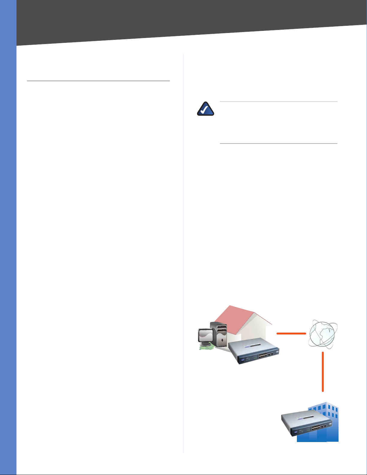
VPN Router to VPN Router
For example, at home, a telecommuter uses his VPN
Router for his always-on Internet connection. His Router
is configured with his office’s VPN settings. When he
connects to his office’s router, the two routers create a
VPN tunnel, encrypting and decrypting data. As VPNs use
the Internet, distance is not a factor. Using the VPN, the
telecommuter now has a secure connection to the central
office’s network, as if he were physically connected.
Home
VPN Router
Internet
Central Office
computer (using VPN client software) to VPN Router •
The VPN Router creates a “tunnel” or channel between two
endpoints, so that data transmissions between them are
secure. A computer with VPN client software can be one
of the two endpoints.
10/100 8-Port VPN Router
VPN Router
VPN Router to VPN Router
1
Page 9
Chapter 1
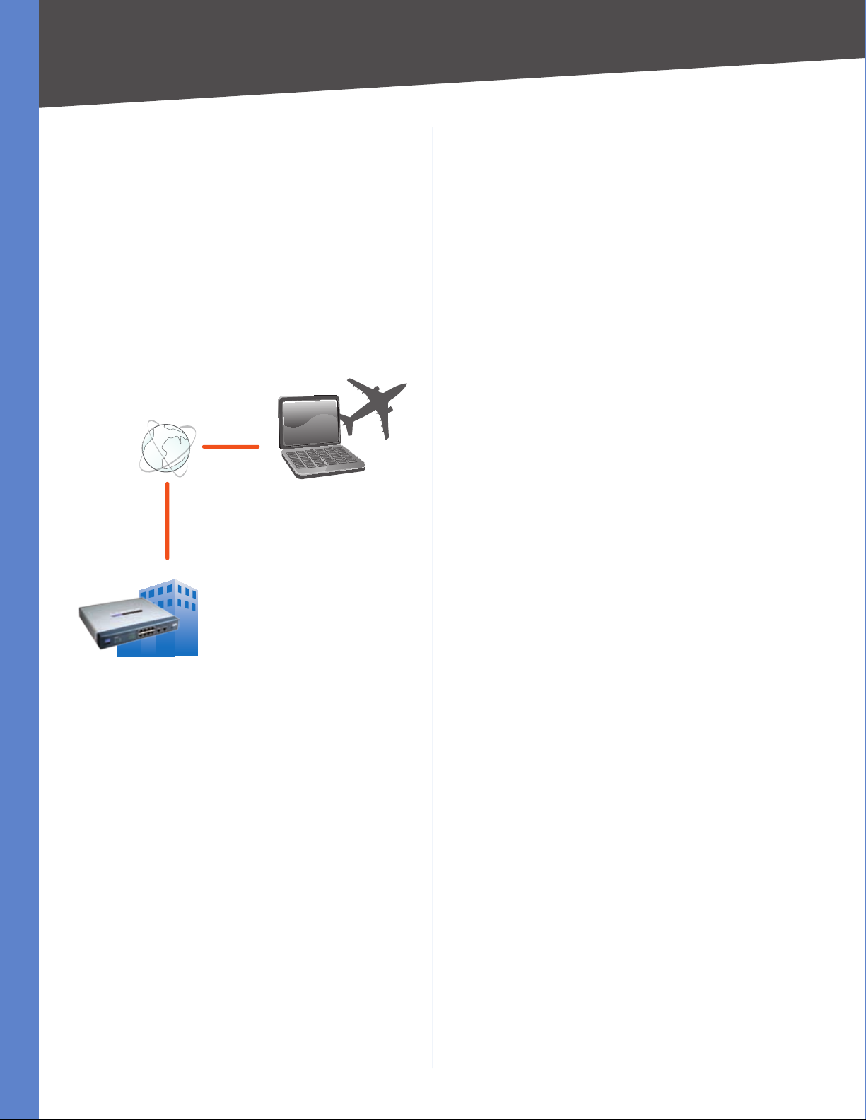
Computer (using VPN client software) to VPN Router
The following is an example of a computer-to-VPN Router
VPN. In her hotel room, a traveling businesswoman
connects to her Internet Service Provider (ISP). Her
notebook computer has VPN client software that is
configured with her office’s VPN settings. She accesses
the VPN client software and connects to the VPN Router
at the central office. As VPNs use the Internet, distance is
not a factor. Using the VPN, the businesswoman now has a
secure connection to the central office’s network, as if she
were physically connected.
Off-Site
Internet
Introduction
Notebook with VPN
Client Software
VPN
Router
For additional information and instructions about
creating your own VPN, visit the Linksys website at
www.linksys.com.
Central Office
Computer to VPN Router
10/100 8-Port VPN Router
2
Page 10
Chapter 2
Product Overview
Chapter 2: Product Overview
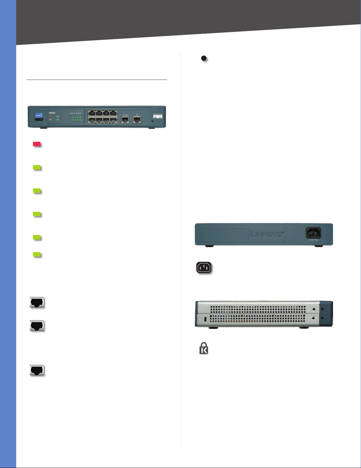
Front Panel
Diag (Red) The Diag LED lights up when the
Router is not ready for use. It turns off when the
Router is ready for use.
System (Green) The System LED lights up
when the Router is powered on. It flashes when
the Router is running a diagnostic test.
Internet (Green) The Internet LED lights up
when the Router is connected to a cable or DSL
modem through the Internet (WAN1) port.
DMZ/Internet (Green) The DMZ/Internet LED
lights up when the Router is actively connected
through the DMZ/Internet (WAN2) port.
DMZ Mode (Green) The DMZ Mode LED lights
up when the Router is using DMZ mode.
Reset The Reset button can be used for a warm
reset or a reset to factory defaults.
Warm Reset • If the Router is having
problems connecting to the Internet,
press and hold in the Reset button for a
second using the tip of a pen. This is similar
to pressing the power button on your
computer to reboot it.
Reset to Factory Defaults • If you are
experiencing extreme problems with
the Router and have tried all other
troubleshooting measures, press and hold
in the Reset button for 30 seconds. This will
restore the factory defaults and clear all of
the Router’s custom settings.
You can also reset the Router to factory
defaults using the System Management >
Factory Default screen of the Router’s
web-based utility.
Back Panel
1, 2, 3, 4, 5, 6, 7, 8 (LAN) (Green) These
numbered LEDs, corresponding with the
numbered ports, serve two purposes. The LED
is solidly lit when the Router is connected to
a device through that port. The LED flashes to
indicate network activity over that port.
1, 2, 3, 4, 5, 6, 7, 8 (LAN) These Ethernet ports
connect the Router to wired computers and
other Ethernet network devices.
DMZ/Internet (WAN2) This port can be used
in one of two ways, a second Internet port or
DMZ port. When used as an additional Internet
port, it connects to a cable or DSL modem.
When used as a DMZ port, it connects to a
switch or public server.
Internet (WAN1) This port connects to a cable
or DSL modem.
Power The Power port connects to the AC
power cord.
Left Side Panel
Security Slot You can attach a lock to the
security slot so the Router will be protected
from theft.
10/100 8-Port VPN Router
3
Page 11
Chapter 3
94 mm
Installation
Chapter 3: Installation
Physical Installation
There are three ways to place the Router. The first way is
to place the Router horizontally on a surface. The second
way is to mount the Router on a wall. The third way is to
mount the Router in a standard-sized, 19-inch high rack.
Horizontal Placement
The Router has four rubber feet on its bottom panel. Set
the Router on a flat surface near an electrical outlet.
WARNING: Do not place excessive weight
on top of the Router; too much weight could
damage it.
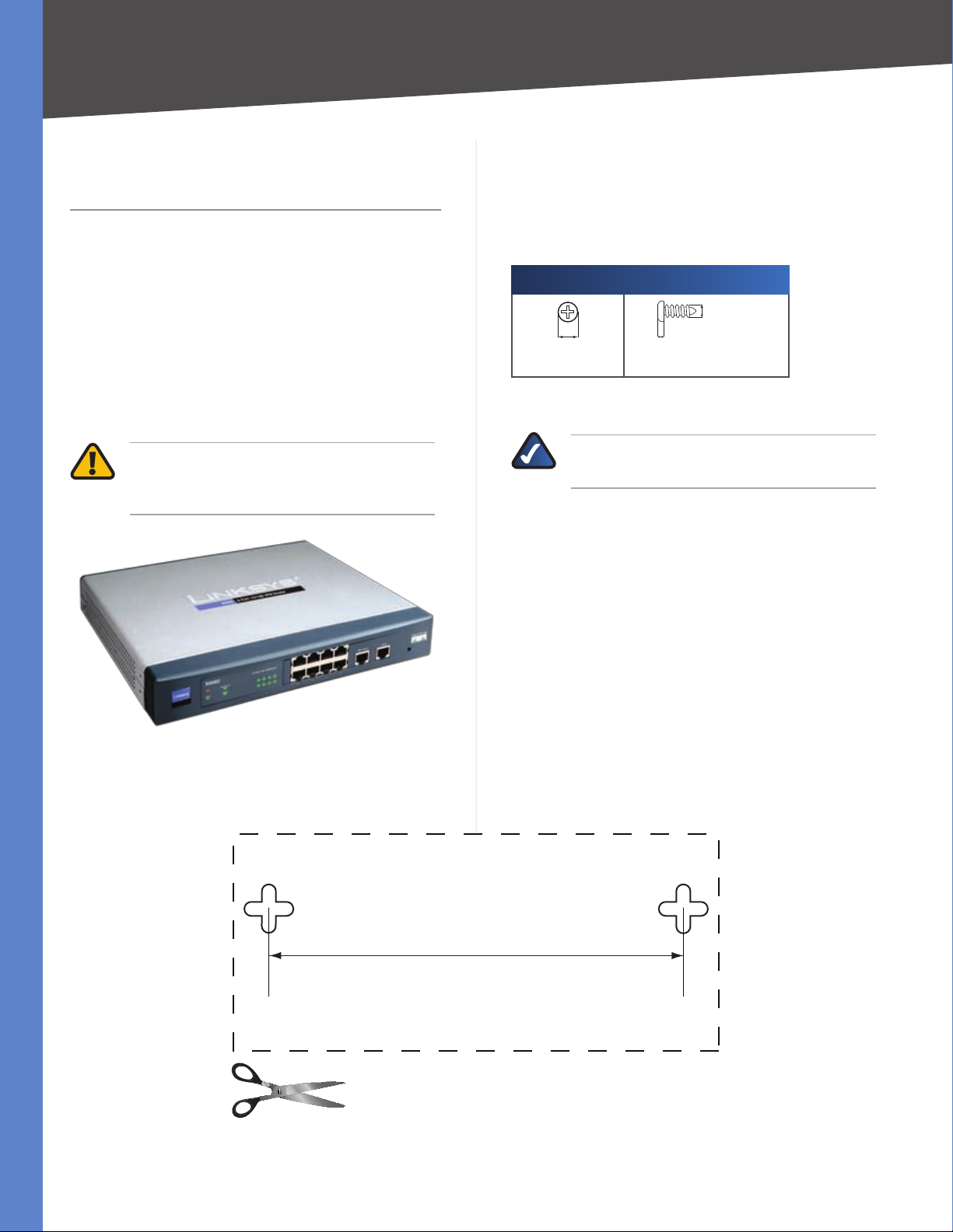
Wall-Mount Placement
The Router has two wall-mount slots on its bottom
panel. The distance between the two slots is 94 mm
(3.70 inches).
Two screws are needed to mount the Router.
Suggested Mounting Hardware
5-6 mm 1.6-2 mm
Note: Mounting hardware illustrations are not †
true to scale.
NOTE: Linksys is not responsible for damages
incurred by insecure wall-mounting hardware.
Follow these instructions:
Determine where you want to mount the Router. Make 1.
sure that the wall you use is smooth, flat, dry, and
sturdy. Also make sure the location is within reach of
an electrical outlet.
3-3.8 mm
Drill two holes into the wall. Make sure the holes are 2.
94 mm (3.07 inches) apart.
Insert a screw into each hole and leave 2 mm 3.
(0.8 inches) below the head exposed.
Maneuver the Router so two of the wall-mount slots 4.
line up with the two screws.
10/100 8-Port VPN Router
Print this page at 100% size. Cut along the dotted line,
and place on the wall to drill precise spacing.
Wall Mounting Template
4
Page 12
Chapter 3
Installation
Place the wall-mount slots over the screws and slide 5.
the Router down until the screws fit snugly into the
wall-mount slots.
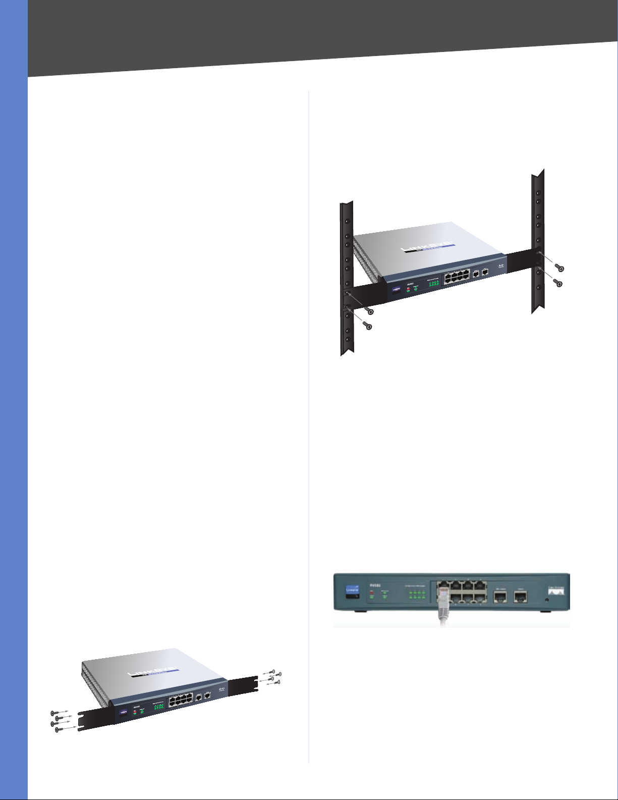
Rack-Mount Placement
The Router includes two brackets and eight screws for
mounting on a standard-sized, 19-inch high rack. Observe
the following guidelines:
Elevated Operating Ambient • If installed in a closed
or multi-unit rack assembly, the operating ambient
temperature of the rack environment may be greater
than room ambient. Therefore, consideration should
be given to installing the equipment in an environment
compatible with the maximum ambient temperature
(Tma) specified by the manufacturer.
Reduced Air Flow • Installation of the equipment
in a rack should be such that the amount of air flow
required for safe operation of the equipment is not
compromised.
Mechanical Loading • Mounting of the equipment in
the rack should be such that a hazardous condition is
not achieved due to uneven mechanical loading.
Repeat step 2 to attach the other bracket to the 3.
opposite side.
After the brackets are attached to the Router, use 4.
suitable screws to securely attach the brackets to any
standard 19-inch rack.
Mount in Rack
Circuit Overloading • Consideration should be given
to the connection of the equipment to the supply
circuit and the effect that overloading of the circuits
might have on overcurrent protection and supply
wiring. Appropriate consideration of equipment
nameplate ratings should be used when addressing
this concern.
Reliable Earthing • Reliable earthing of rack-mounted
equipment should be maintained. Particular attention
should be given to supply connections other than
direct connections to the branch circuit (e.g., use of
power strips).
To rack-mount the Router in any standard 19-inch rack,
follow these instructions.
Place the Router on a hard flat surface with the front 1.
panel faced towards your front side.
Attach a rack–mount bracket to one side of the Router 2.
with the supplied screws and secure the bracket
tightly.
Cable Connections
To connect network devices to the Router, follow these
instructions:
Before you begin, make sure that all of your hardware 1.
is powered off, including the Router, computers,
switches, and cable or DSL modem.
Connect one end of an Ethernet network cable to one 2.
of the numbered ports. Connect the other end to an
Ethernet port on a network device, such as a computer
or switch.
Repeat this step to connect more computers or other
network devices to the Router.
Connect to Port 1
10/100 8-Port VPN Router
Attach the Brackets
5
Page 13
Chapter 3
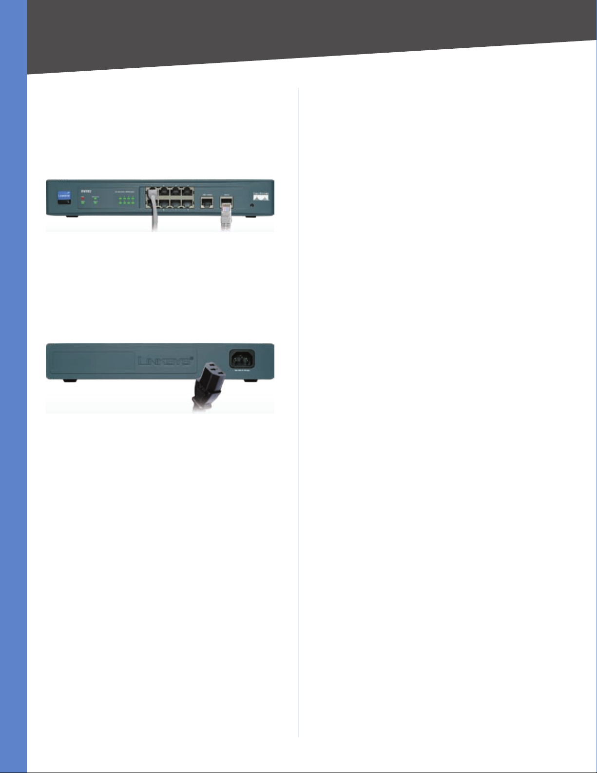
Connect your cable or DSL modem’s Ethernet 3.
cable to the Router’s Internet port.
If you are using the DMZ/Internet port, then connect
an Ethernet cable to the DMZ/Internet port. Connect
the other end to a network device, such as a modem
or public server.
Connect to the Internet Port
Power on the cable or DSL modem. If you have a 4.
network device connected to the DMZ/Internet port,
power on the network device.
Connect the included power cord to the Router’s 5.
Power port, and then plug the power cord into an
electrical outlet.
Installation
Connect the Power
The System LED on the front panel will light up as soon 6.
as the power adapter is connected properly.
Power on your computers and other network devices.7.
10/100 8-Port VPN Router
6
Page 14
Chapter 4
Advanced Configuration
Chapter 4: Advanced Configuration
Overview
The Router’s web-based utility allows you to set up
the Router and perform advanced configuration and
troubleshooting. This chapter will explain all of the
functions in this utility.
These are the main tabs of the utility: System Summary,
Setup, DHCP, System Management, Port Management,
Firewall, VPN, Log, Wizard, Support, and Logout. (The
ProtectLink tab is available with upgraded firmware.)
Additional tabs will be available after you click one of the
main tabs.
How to Access the Web-Based Utility
For local access of the Router’s web-based utility, 1.
launch your web browser, and enter the Router’s
default IP address, 192.168.1.1, in the Address field.
Press the Enter key.
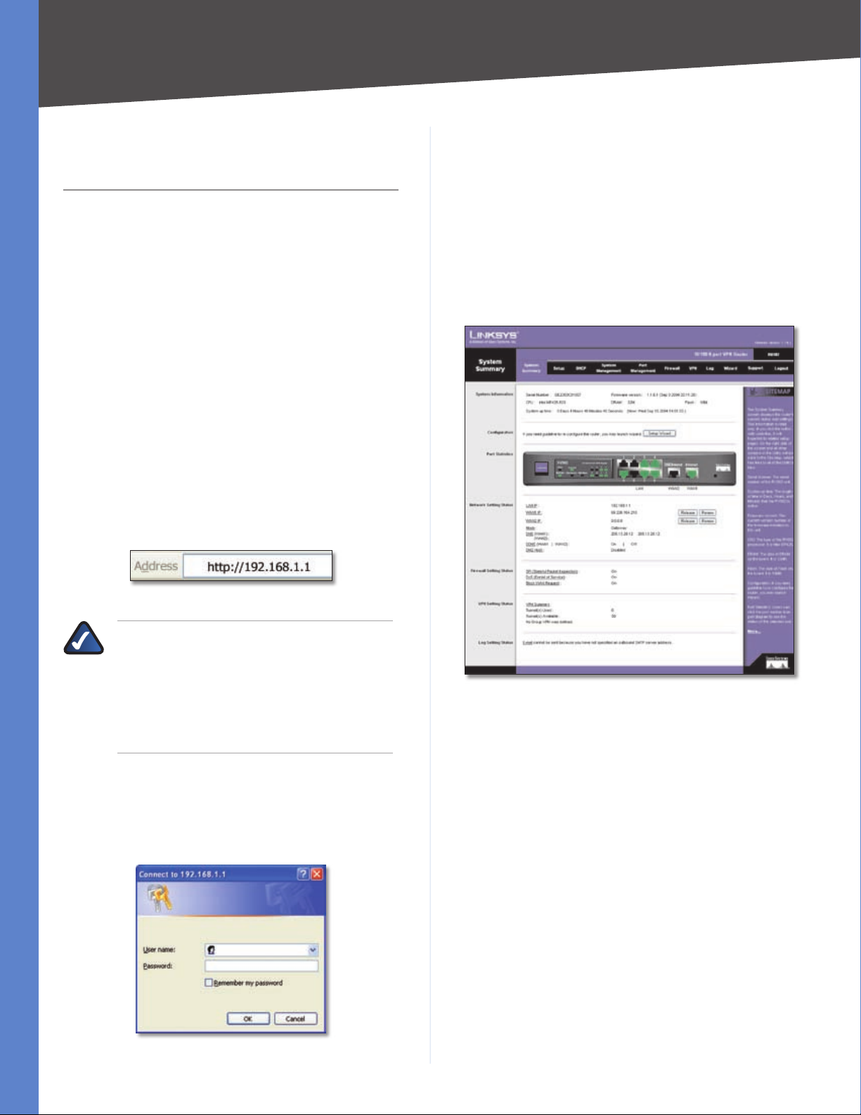
System Summary
The first screen that appears is the System Summary
screen, which displays the Router’s current status and
settings. This information is read-only. Underlined text
is hyperlinked to related setup pages, so if you click a
hyperlink, the related setup screen will appear. On the
right-hand side of this screen and all other screens of the
utility is a link to the Site Map, which has links to all of the
utility’s tabs. Click Site Map to view the Site Map. Then,
click the desired tab.
Address Bar
NOTE: If the Remote Management feature on
the Firewall > General screen has been enabled,
then users with administrative privileges can
remotely access the web-based utility. Use
http://<WAN IP address of the Router>, or
use https://<WAN IP address of the Router> if
you have enabled the HTTPS feature.
A login screen prompts you for your User name and 2.
Password. Enter admin in the User name field, and
enter admin in the Password field. (You can change
the Password on the Setup > Password screen.) Then
click OK.
System Summary
10/100 8-Port VPN Router
Login Screen
7
Page 15
Chapter 4
Advanced Configuration
System Up Time This is the length of time in days, hours,
and minutes that the Router has been active. The current
time and date are also displayed.
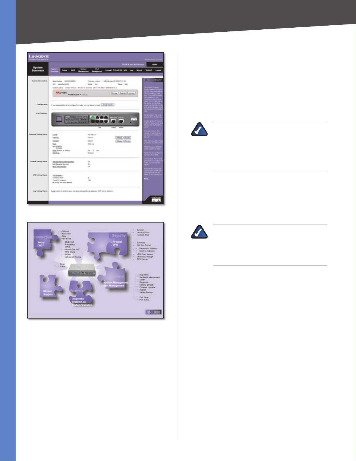
Trend Micro™ ProtectLink Gateway
The optional Trend Micro ProtectLink Gateway service
provides security for your network. It checks e-mail
messages, filters website addresses (URLs), and blocks
potentially malicious websites.
NOTE: If the Trend Micro ProtectLink Gateway
options are not displayed on the System
Summary screen, you can upgrade the Router’s
firmware if you want to purchase and use this
optional service. Refer to “Appendix F: Firmware
Upgrade” for instructions.
Go buy To purchase a license to use this service, click Go
buy. You will be redirected to a list of Linksys resellers on the
Linksys website. Then follow the on-screen instructions.
System Summary (ProtectLink™ Available)
Site Map
System Information
Serial Number Displayed here is the serial number of the
Router.
Firmware version Displayed here is the current version
number of the firmware installed on the Router.
CPU Displayed here are the type and speed of the
processor installed on the Router.
DRAM Displayed here is the size of DRAM installed on
the Router’s motherboard.
Flash Displayed here is the size of flash memory installed
on the Router’s board.
Register If you already have a license, click Register. You
will be redirected to the Trend Micro ProtectLink Gateway
website. Then follow the on-screen instructions.
NOTE: To have your e-mail checked, you will
need to provide the domain name and IP
address of your e-mail server. If you do not
know this information, contact your Internet
Service Provider (ISP).
Activate If you have registered, click Activate. You will
be redirected to the Trend Micro ProtectLink Gateway
website. Follow the on-screen instructions.
For more information, refer to “Appendix G: Trend Micro
ProtectLink Gateway Service.”
Configuration
If you need help to configure the Router, click Setup
Wizard, and follow the on-screen instructions. For
additional information, refer to the “Wizard” section of this
chapter.
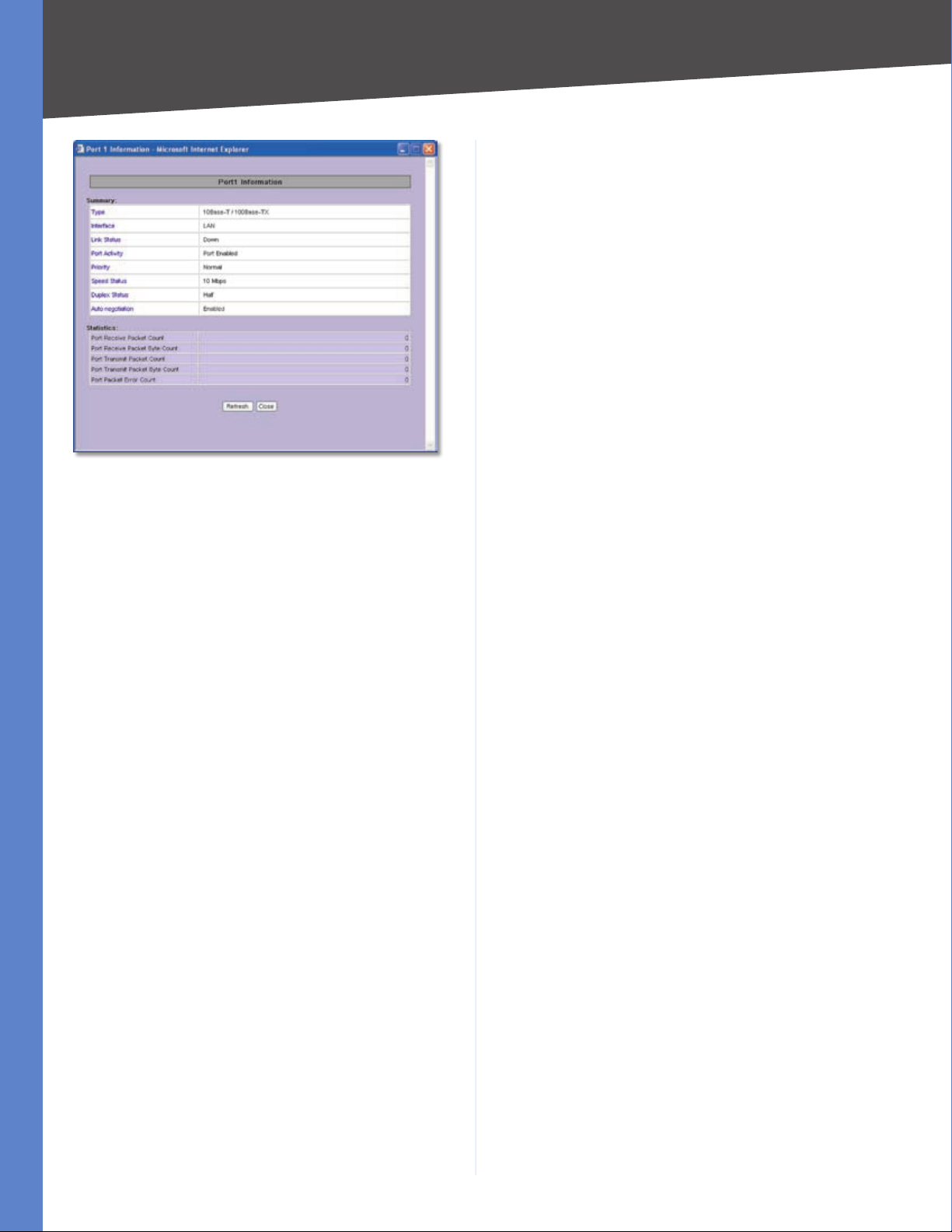
Port Statistics
The image of the Router’s front panel displays the status
of each port. If a port is disabled, it will be red; if a port is
enabled, it will be black. If a port is connected, it will be
green. Click any port to view the port’s Summary table in
a separate window.
The Summary table shows the settings of the selected
port, including Type, Interface, Link Status, Port Activity,
Priority, Speed Status, Duplex Status, Auto negotiation,
and VLAN.
10/100 8-Port VPN Router
8
Page 16
Chapter 4
Port 1 Information
Advanced Configuration
DDNS It shows the DDNS settings of the Router’s WAN
port(s) and hyperlinks to the Setup > DDNS screen.
DMZ Host It shows the DMZ private IP address and
hyperlinks to the Setup > DMZ Host screen. The default is
Disabled.
Firewall Setting Status
SPI (Stateful Packet Inspection) It shows the status
(On/Off) of the SPI setting and hyperlinks to the Firewall >
General screen.
DoS (Denial of Service) It shows the status (On/Off) of
the DoS setting and hyperlinks to the Firewall > General
screen.
Block WAN Request It shows the status (On/Off ) of
the Block WAN Request setting and hyperlinks to the
Firewall > General screen.
For the selected port, the statistics table shows this
information: number of packets received, number of
packet bytes received, number of packets transmitted,
number of packet bytes transmitted, and number of
packet errors.
To update the on-screen information, click Refresh. To
exit this screen, click Close.
Network Setting Status
LAN IP It shows the current LAN IP address of the Router,
as seen by internal users on the network, and it hyperlinks
to the LAN Setting section on the Network screen of the
Setup tab.
WAN1 IP This shows the current WAN1 IP address of
the Router, as seen by external users on the Internet and
hyperlinks to the WAN Connection Type settings on the
Setup > Network screen. If the port is set to Obtain an IP
automatically, two buttons, Release and Renew, will be
available. Click Release to release the IP address, and
click Renew to update the DHCP Lease Time or get a new
IP address. If the WAN port is set to PPPoE or PPTP, two
buttons, Connect and Disconnect, will be available.
WAN2/DMZ IP This shows the current WAN2 IP address
of the Router, or DMZ IP address when DMZ is selected, as
seen by external users on the Internet and hyperlinks to
the WAN Connection Type settings on the Setup > Network
screen.
Mode It shows the Router’s Working Mode (Gateway or
Router), and it hyperlinks to the Dynamic Routing section
on the Setup > Advanced Routing screen.
DNS It shows all DNS server IP addresses and hyperlinks
to the WAN Connection Type settings on the Setup >
Network screen.
VPN Setting Status
VPN Summary It hyperlinks to the VPN > Summary
screen.
Tunnel(s) Used It shows the number of VPN tunnels
used.
Tunnel(s) Available It shows the number of VPN tunnels
available.
Current Connected (The Group Name of GroupVPN1)
users It shows the number of users. (If the GroupVPN
feature is disabled, the message, “No Group VPN was
defined”, is displayed.)
Current Connected (The Group Name of GroupVPN2)
users It shows the number of users.
Log Setting Status
It hyperlinks to the Log > System Log screen of the Log
tab.
If you have not set up the e-mail server on the Log tab,
the message, “E-mail cannot be sent because you have
not specified an outbound SMTP server address,” will be
displayed.
If you have set up the mail server but the log has not been
generated due to the Log Queue Length and Log Time
Threshold settings, the message, “E-mail settings have
been configured,” will be displayed.
If you have set up the e-mail server and the log has been
sent to the e-mail server, the message, “E-mail settings
have been configured and sent out normally,” will be
displayed.
If you have set up the e-mail server and the log cannot
be sent to the e-mail server, the message, “E-mail cannot
10/100 8-Port VPN Router
9
Page 17
Chapter 4
be sent out, probably use incorrect settings,” will be
displayed.
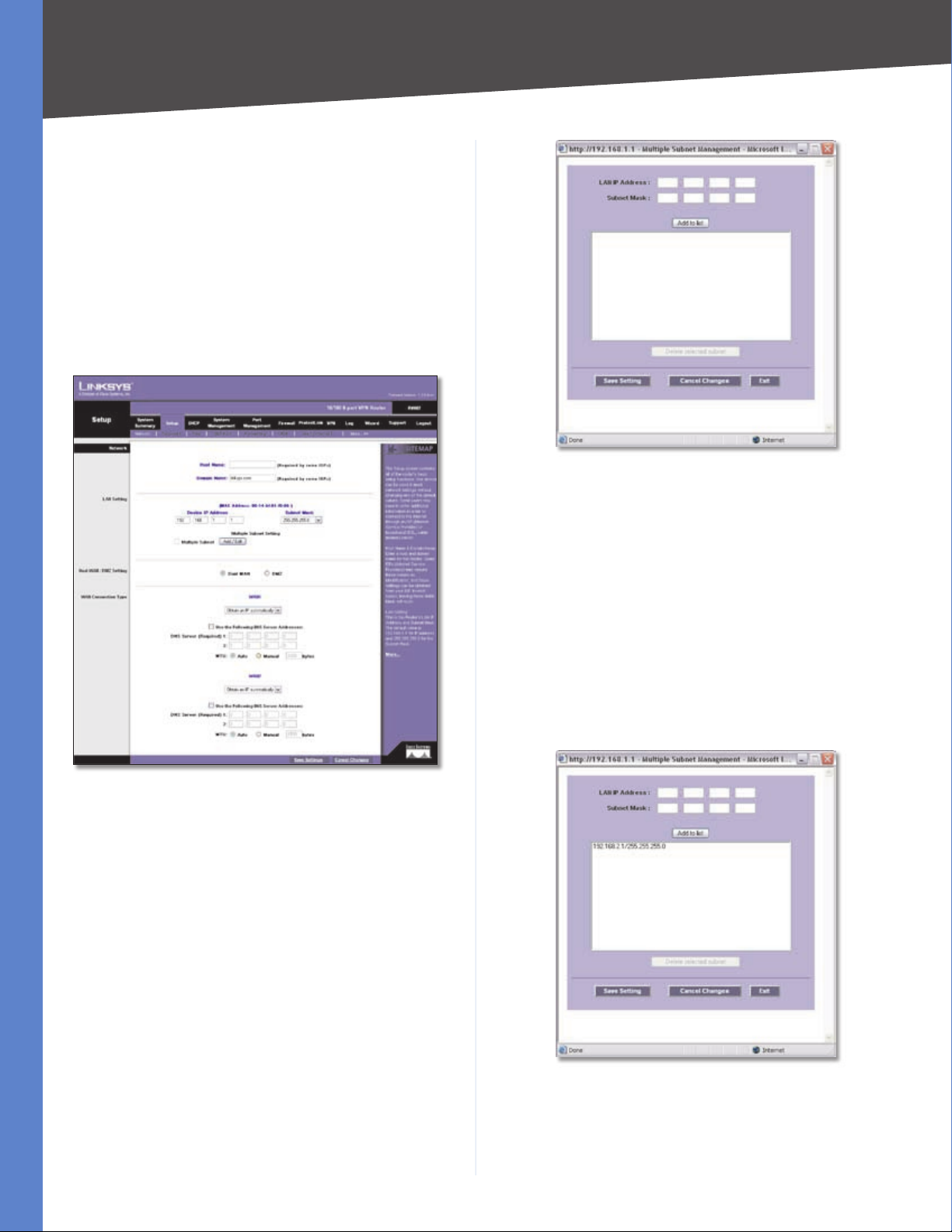
Setup > Network
The Network screen shows all of the Router’s basic setup
functions. The Router can be used in most network setups
without changing any of the default values; however,
you may need to enter additional information in order to
connect to the Internet through an ISP (Internet Service
Provider) or broadband (DSL or cable) carrier. The setup
information is provided by your ISP.
Advanced Configuration
Create or Modify a Subnet
LAN IP Address Enter the LAN IP address.
Setup > Network
Network
Host Name and Domain Name Enter a host and domain
name for the Router. Some ISPs require these names as
identification. You may have to check with your ISP to see
if your broadband Internet service has been configured
with a host and domain name. In most cases, you can
leave these fields blank.
Subnet Mask Enter the subnet mask.
For example, the current LAN settings show the Device
IP Address as 192.168.1.1 and the Subnet Mask as
255.255.255.0. To add one more Class C network, enter
the following:
LAN IP Address • 192.168.2.1
Subnet Mask • 255.255.255.0
Click Add to List. Click Save Settings to save your changes,
or click Cancel Changes to undo them. Click Exit to return
to the Network screen.
LAN Setting
The LAN MAC address of the Router is displayed.
Device IP Address and Subnet Mask The default values
are 192.168.1.1 for the Router’s local IP address and
255.255.255.0 for the subnet mask.
Multiple Subnet You can add more Class C networks
to expand the network. Select this option to enable the
Multiple Subnet feature. Then click Add/Edit to create or
modify subnet(s). A new screen appears.
10/100 8-Port VPN Router
Add One More Class C Network
If you want to modify a subnet you have created, select
it and make changes. Click Save Settings to save your
changes, or click Cancel Changes to undo them. Click
Exit to return to the Network screen.
10
Page 18
Chapter 4
Advanced Configuration
If you want to delete a subnet you have created, select it
and click Delete selected subnet. Click Save Settings
to save your changes, or click Cancel Changes to undo
them. Click Exit to return to the Network screen.
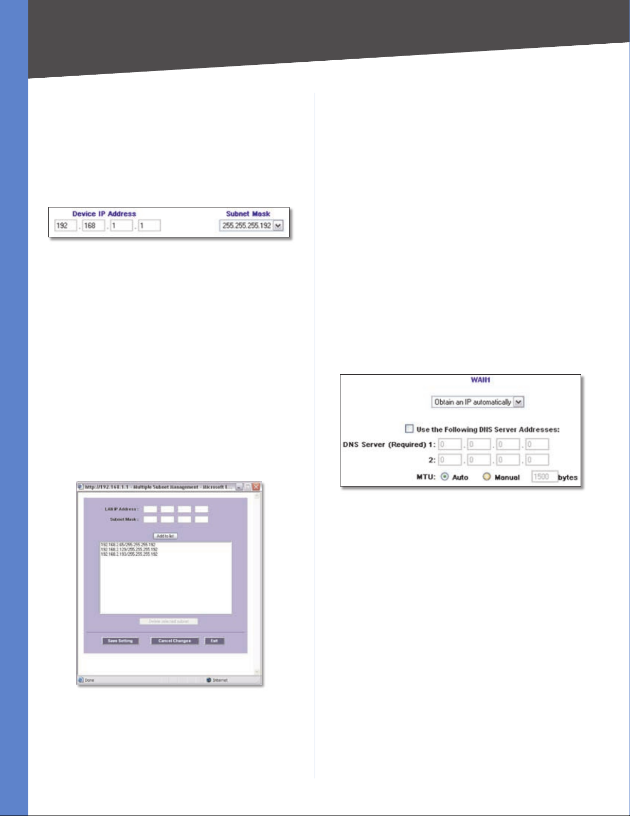
You can also divide a Class C network into four subnets.
For example, the current LAN settings show the Device
IP Address as 192.168.1.1 and the Subnet Mask as
255.255.255.192.
LAN Settings Example
To get the other three subnets, enter the following:
Subnet 1
LAN IP Address • 192.168.2.65
Subnet Mask • 255.255.255.192
Subnet 2
LAN IP Address • 192.168.2.129
Subnet Mask • 255.255.255.192
the Router. On the System Management > Dual-WAN screen,
you can specify using one as a primary connection, with
Smart Link Backup or using both connections in concert,
with Load Balance. The DMZ setting allows one network
PC to be exposed to the Internet to use special-purpose
services, such as Internet gaming or videoconferencing.
WAN Connection Type
Configure the settings for the WAN or DMZ ports.
WAN1/2
These are the available connection types: Obtain an IP
automatically, Static IP, PPPoE, PPTP, Transparent Bridge,
and Heart Beat Signal. Depending on which connection
type you select, you will see various settings.
Obtain an IP Automatically
If your ISP automatically assigns an IP address, select
Obtain an IP automatically. (Most cable modem
subscribers use this connection type.) Your ISP assigns
these values.
Subnet 3
LAN IP Address • 192.168.2.193
Subnet Mask • 255.255.255.192
Click Add to List. Then click Save Settings.
Create Three Additional Subnets
Dual-WAN/DMZ Setting
Before configuring the WAN Connection Type settings,
select Dual WAN or DMZ. The Dual WAN setting allows you
to simultaneously connect two broadband connections to
Obtain an IP Automatically
Use the Following DNS Server Addresses If you want to
specify DNS server IP addresses, select this option.
DNS Server (Required) 1/2 If you select Use the Following
DNS Server Addresses, enter at least one DNS server IP
address. Multiple DNS server IP settings are common. In
most cases, the first available DNS entry is used.
MTU The Maximum Transmission Unit (MTU) setting
specifies the largest packet size permitted for network
transmission. In most cases, keep the default, Auto.
To specify the MTU, select Manual, and then enter the
maximum MTU size.
Click Save Settings to save your changes, or click Cancel
Changes to undo them.
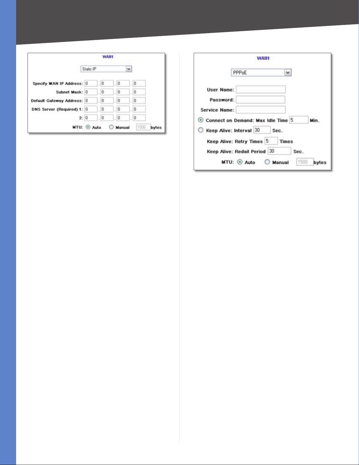
Static IP
If you are required to use a permanent IP address, select
Static IP.
10/100 8-Port VPN Router
11
Page 19
Chapter 4
Static IP
Specify WAN IP Address Enter the external IP address of
the Router.
Subnet Mask Enter the subnet mask of the Router.
Default Gateway Address Enter the IP address of the
default gateway.
DNS Server (Required) 1/2 Enter at least one DNS server
IP address. Multiple DNS server IP settings are common. In
most cases, the first available DNS entry is used.
MTU The Maximum Transmission Unit (MTU) setting
specifies the largest packet size permitted for network
transmission. In most cases, keep the default, Auto.
To specify the MTU, select Manual, and then enter the
maximum MTU size.
Click Save Settings to save your changes, or click Cancel
Changes to undo them.
PPPoE (Point-to-Point Protocol over Ethernet)
Some DSL-based Internet Service Providers (ISPs) use
PPPoE (Point-to-Point Protocol over Ethernet) to establish
Internet connections for end-users. If you use a DSL
line, check with your ISP to see if they use PPPoE, select
PPPoE.
Advanced Configuration
PPPoE
User Name and Password Enter your account’s User
Name and Password. The maximum number of characters
is 60.
Service Name Enter the Service Name, if provided by
your ISP.
Connect on Demand If you select the Connect on
Demand option, the connection will be disconnected
after a specified period of inactivity (Max Idle Time). If you
have been disconnected due to inactivity, Connect on
Demand enables the Router to automatically re-establish
your connection as soon as you attempt to access the
Internet again. Enter the number of minutes you want to
have elapsed before your Internet access disconnects. The
default Max Idle Time is 5 minutes.
Keep Alive: Interval If you select the Keep Alive option,
the Router will send keep-alive packets as often as you
specify. The default Interval is 30 seconds.
Keep Alive: Retry Times If you select the Keep Alive
option, the Router will send keep-alive packets as many
times as you specify. If the Router does not receive a
response from the ISP, then the Router will terminate the
connection and start sending PADI packets after the Redial
Period. The default Retry Times is 5 times.
10/100 8-Port VPN Router
Keep Alive: Redial Period If you select the Keep Alive
option, the Router will keep the connection alive by
sending out a few data packets periodically, so your ISP
thinks that the connection is still active. This option keeps
your connection active indefinitely, even when it sits idle.
The default Redial Period is 30 seconds.
MTU The Maximum Transmission Unit (MTU) setting
specifies the largest packet size permitted for network
transmission. In most cases, keep the default, Auto.
To specify the MTU, select Manual, and then enter the
maximum MTU size.
12
Page 20
Chapter 4
Advanced Configuration
Click Save Settings to save your changes, or click Cancel
Changes to undo them.
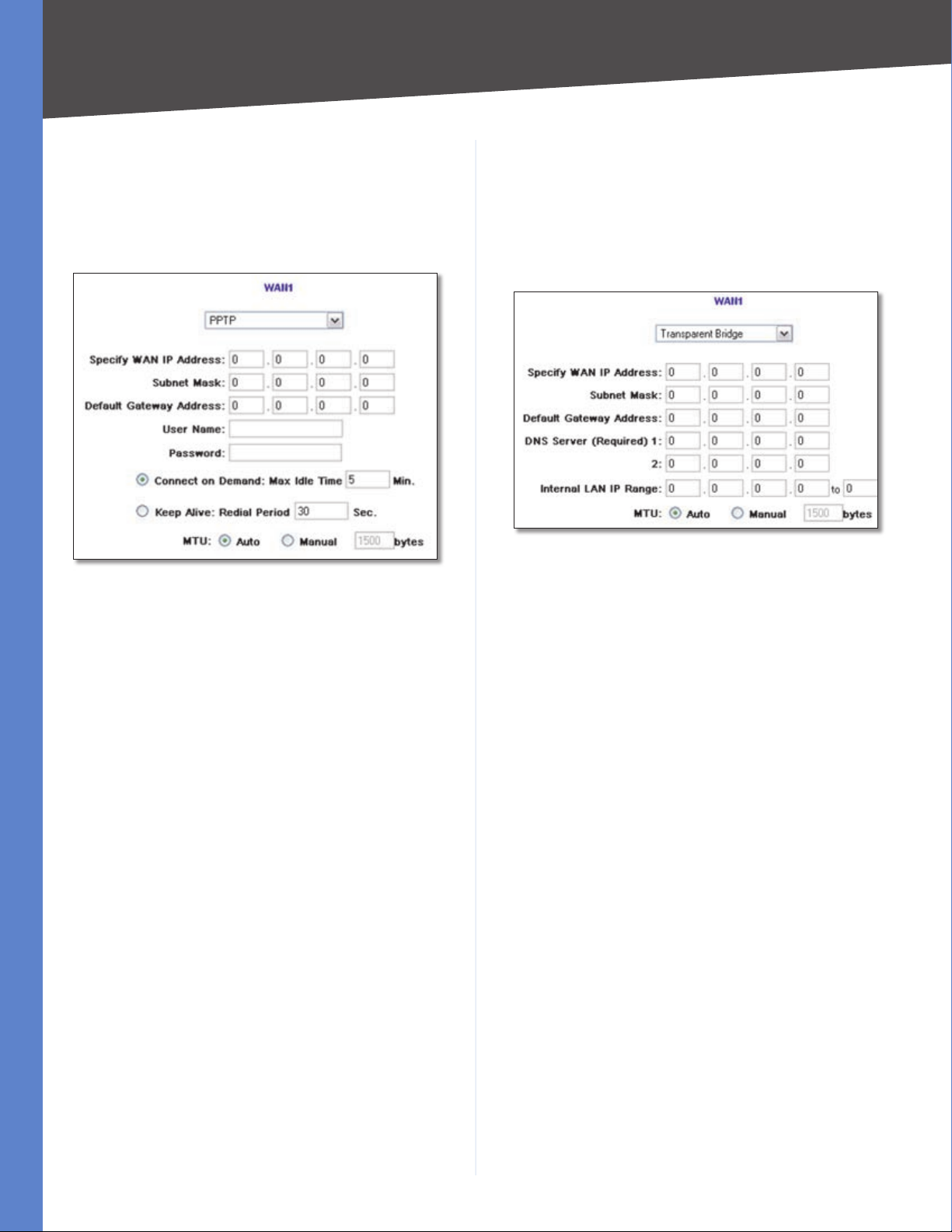
PPTP (Point-to-Point Tunneling Protocol)
Point to Point Tunneling Protocol (PPTP) is a service used
in Europe, Israel, and other countries.
PPTP
Specify WAN IP Address Enter the external IP address of
the Router.
Subnet Mask Enter the subnet mask of the Router.
Default Gateway Address Enter the IP address of the
default gateway.
User Name and Password Enter your account’s User
Name and Password. The maximum number of characters
is 60.
Connect on Demand If you select the Connect on
Demand option, the connection will be disconnected
after a specified period of inactivity (Max Idle Time). If you
have been disconnected due to inactivity, Connect on
Demand enables the Router to automatically re-establish
your connection as soon as you attempt to access the
Internet again. Enter the number of minutes you want to
have elapsed before your Internet access disconnects. The
default Max Idle Time is 5 minutes.
Keep Alive If you select the Keep Alive option, the Router
will keep the connection alive by sending out a few data
packets periodically, so your ISP thinks that the connection
is still active. This option keeps your connection active
indefinitely, even when it sits idle. The default Redial
Period is 30 seconds.
Click Save Settings to save your changes, or click Cancel
Changes to undo them.
Transparent Bridge
To connect two network segments, select Transparent
Bridge. (You do not need to change the attached network
settings.)
Transparent Bridge
Specify WAN IP Address Enter the external IP address of
the Router.
Subnet Mask Enter the subnet mask of the Router.
Default Gateway Address Enter the IP address of the
default gateway.
DNS Server (Required) 1/2 Enter at least one DNS server
IP address. Multiple DNS server IP settings are common. In
most cases, the first available DNS entry is used.
Internal LAN IP Range Enter the Internal LAN IP Range
that will be bridged. The WAN and LAN of the Transparent
Bridge will be in the same subnet. (Only one WAN of the
Router can be set to the Transparent Bridge mode.)
MTU The Maximum Transmission Unit (MTU) setting
specifies the largest packet size permitted for network
transmission. In most cases, keep the default, Auto.
To specify the MTU, select Manual, and then enter the
maximum MTU size.
Click Save Settings to save your changes, or click Cancel
Changes to undo them.
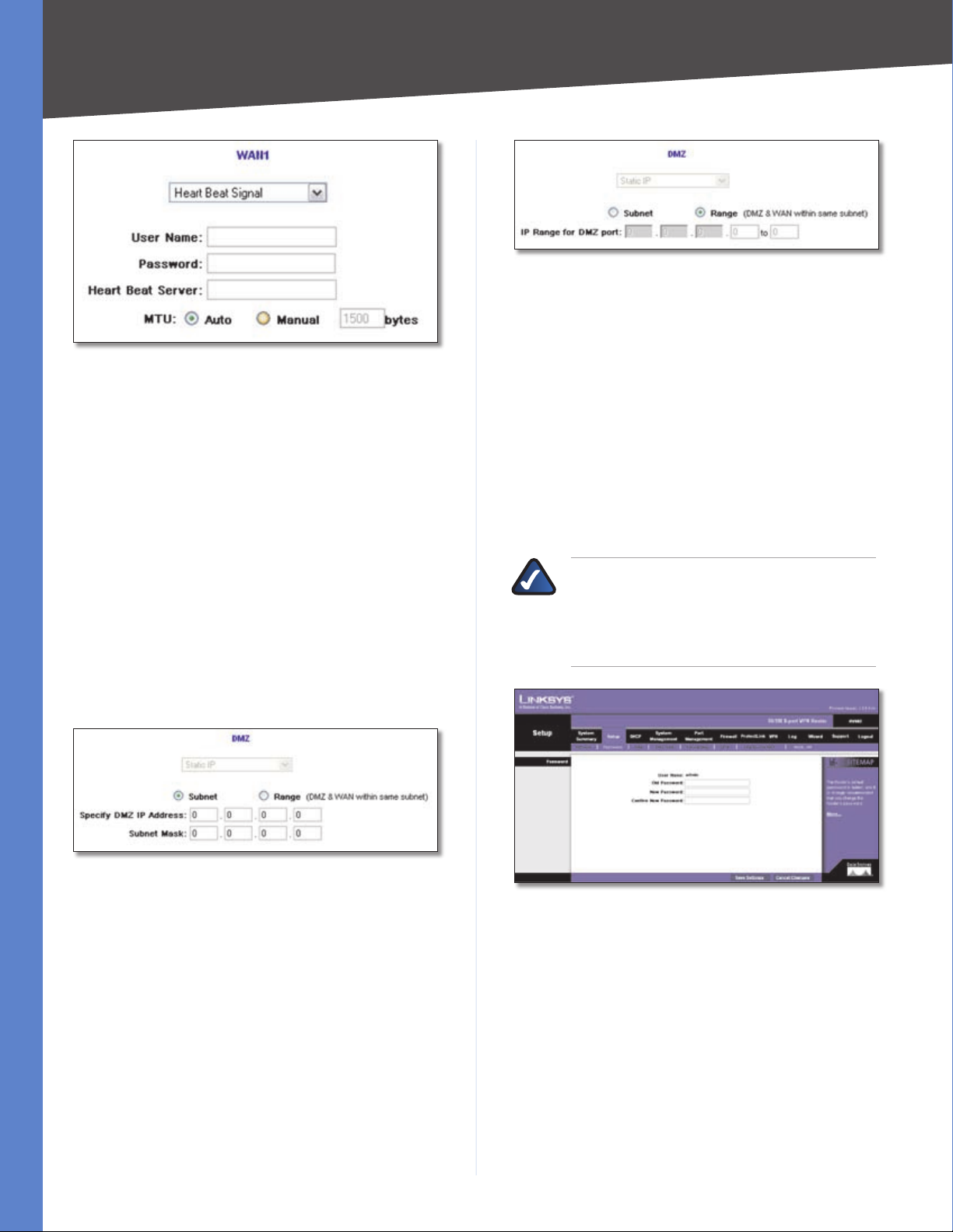
Heart Beat Signal
Heart Beat Signal is a service used in Australia only.
MTU The Maximum Transmission Unit (MTU) setting
specifies the largest packet size permitted for network
transmission. In most cases, keep the default, Auto.
To specify the MTU, select Manual, and then enter the
maximum MTU size.
10/100 8-Port VPN Router
13
Page 21
Chapter 4
Heart Beat Signal
User Name and Password Enter your account’s User
Name and Password. The maximum number of characters
is 60.
Advanced Configuration
DMZ (Range)
Range If Range is selected, the DMZ port and the WAN
port will be in the same subnet. To specify a range, select
this option and configure the following:
IP Range for DMZ port • Enter the starting and ending
IP addresses.
Click Save Settings to save your changes, or click Cancel
Changes to undo them.
Heart Beat Server Enter the IP address of the Heart Beat
server.
MTU The Maximum Transmission Unit (MTU) setting
specifies the largest packet size permitted for network
transmission. In most cases, keep the default, Auto.
To specify the MTU, select Manual, and then enter the
maximum MTU size.
Click Save Settings to save your changes, or click Cancel
Changes to undo them.
DMZ
Static IP is automatically selected. There are two different
DMZ settings: Subnet and Range.
DMZ (Subnet)
Subnet To specify a subnet, select this option and
configure the following:
Specify DMZ IP Address • Enter the IP address of the
computer connected to the DMZ port.
Subnet Mask • Enter the subnet mask of the computer
connected to the DMZ port.
Click Save Settings to save your changes, or click Cancel
Changes to undo them.
Setup > Password
The Router’s default User Name and Password is admin,
and Linksys strongly recommends that you change the
Router’s password from the default to a unique password.
NOTE: The password cannot be recovered if
it is lost or forgotten. If the password is lost or
forgotten, you have to reset the Router to its
factory default settings; this will remove all of
your configuration changes.
Setup > Password
Password
The User Name is admin; it cannot be changed.
Old Password Enter the old password. The default is
admin when you first power up the Router.
New Password Enter a new password for the Router. Your
password must have 20 or fewer characters and cannot
contain any spaces.
10/100 8-Port VPN Router
Confirm New Password Re-enter the new password to
confirm it.
14
Page 22
Chapter 4
Advanced Configuration
Click Save Settings to save your change, or click Cancel
Changes to undo it.
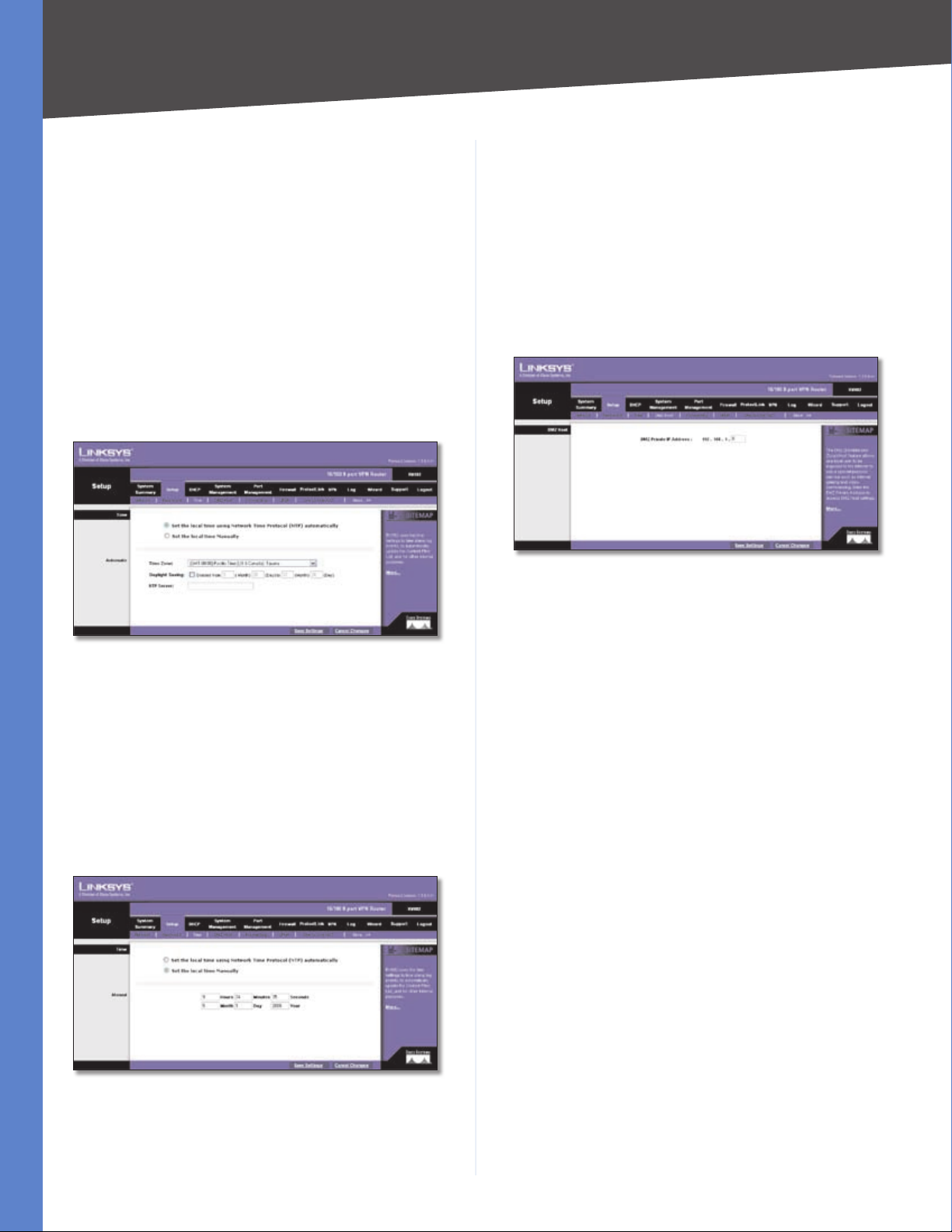
Setup > Time
The Router uses the time settings to time stamp log events,
automatically apply the Access Rules and Content Filter,
and perform other activities for other internal purposes.
Time
To set the local time, select Set the local time using the
Network Time Protocol (NTP) automatically or Set the
local time Manually.
Automatic
Click Save Settings to save your changes, or click Cancel
Changes to undo them.
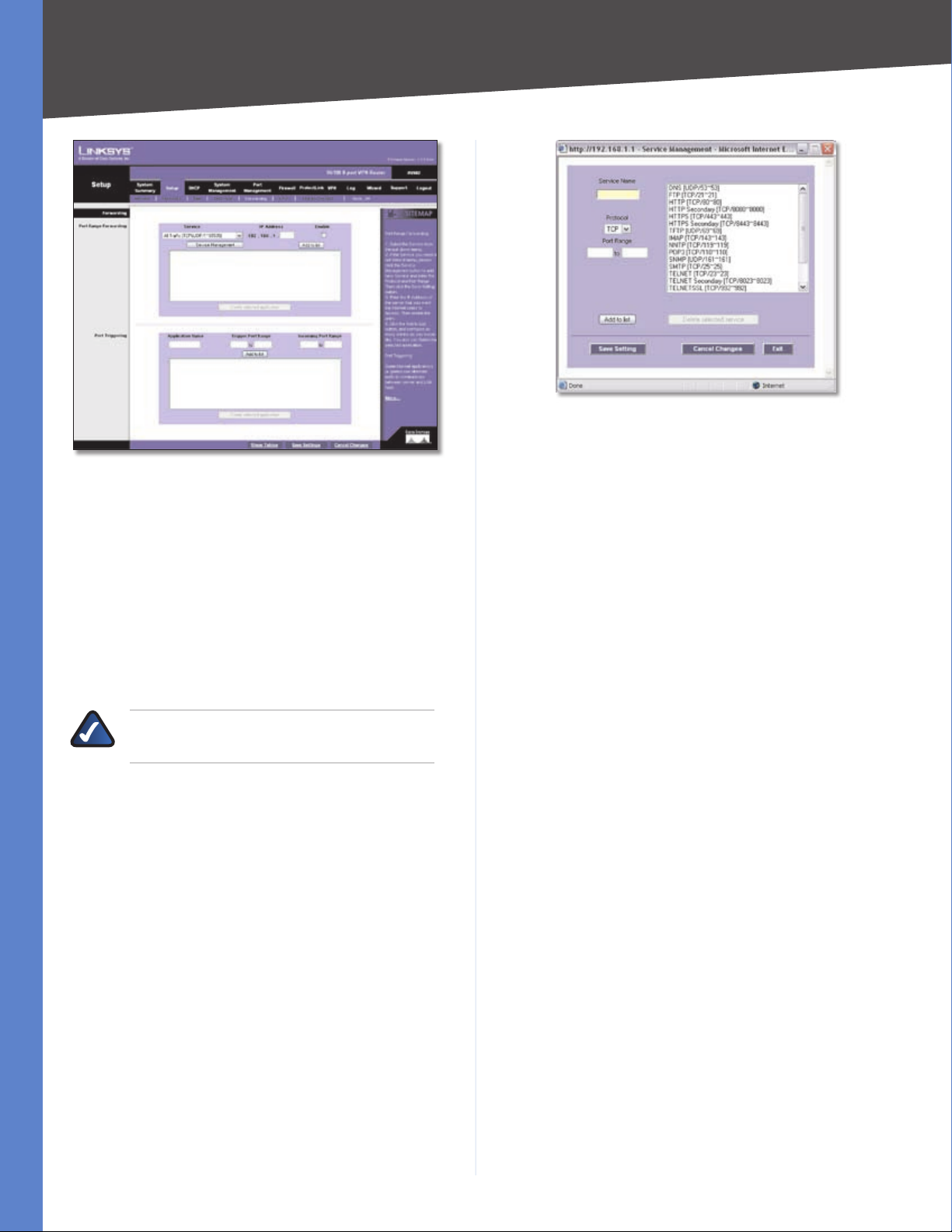
Setup > DMZ Host
The DMZ (Demilitarized Zone) Host feature allows one
local user to be exposed to the Internet for use of a
special-purpose service such as Internet gaming or
videoconferencing. Although Port Range Forwarding can
only forward ten ranges of ports maximum, DMZ hosting
forwards all the ports to one computer at the same time.
Setup > DMZ Host
Setup > Time > Automatic
Time Zone Select your time zone. The default is (GMT-
08:00) Pacific Time (US & Canada); Tijuana.
Daylight Saving To use the daylight saving feature, select
Enabled. Enter the Month and Day of the start date, and
then enter the Month and Day of the end date.
NTP Server Enter the URL or IP address of the NTP server.
The default is time.nist.gov.
Manual
DMZ Host
DMZ Private IP Address Enter the local IP address of
the computer you want to expose. The default value of 0
deactivates the DMZ Host.
Click Save Settings to save your change, or click Cancel
Changes to undo it.
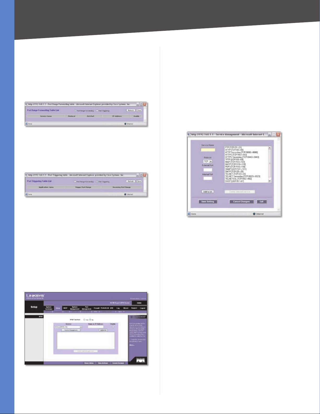
Setup > Forwarding
The Forwarding screen allows you to set up port range
forwarding and port triggering applications. Port range
forwarding can be used to set up public services or other
specialized Internet applications on your network, while
port triggering can be used to set up triggered ranges and
forwarded ranges for Internet applications.
Setup > Time > Manual
Hours, Minutes, Seconds Enter the time.
Month, Day, Year Enter the date.
10/100 8-Port VPN Router
15
Page 23
Chapter 4
Setup > Forwarding
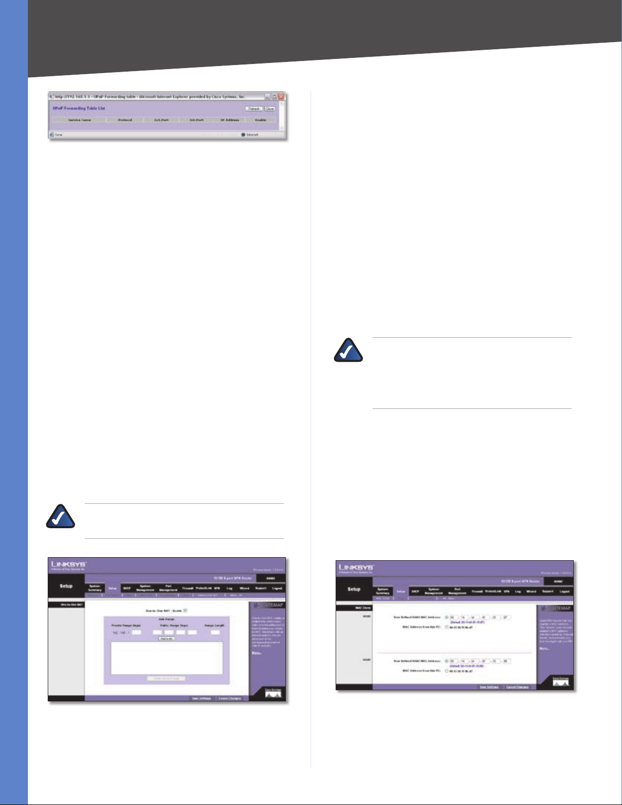
Advanced Configuration
Service Management
Service Name Enter a name.
Protocol Select the protocol it uses.
Forwarding
Port Range Forwarding
Port forwarding can be used to set up public services on
your network. When users from the Internet make certain
requests on your network, the Router can forward those
requests to computers equipped to handle the requests.
If, for example, you set the port number 80 (HTTP) to be
forwarded to IP address 192.168.1.2, then all HTTP requests
from outside users will be forwarded to 192.168.1.2.
NOTE: You must disable the Router’s DHCP
function to use port forwarding.
You may use this function to establish a web server or FTP
server via an IP gateway. Make sure that you enter a valid
IP address. (You may need to establish a static IP address
in order to properly run an Internet server.) For added
security, Internet users will be able to communicate with
the server, but they will not actually be connected. The
packets will simply be forwarded through the Router.
Service Select the Service you want.
IP Address Enter the IP address of the server that you
want the Internet users to access.
Enable Select Enable to enable this port range forwarding
entry.
If the Service you need is not listed in the menu, click
Service Management to add the new service. The Service
Management screen appears.
Port Range Enter its range.
Click Add to List. Click Save Settings to save your changes,
or click Cancel Changes to undo them. Click Exit to return
to the Forwarding screen.
If you want to modify a service you have created, select it
and click Update this service. Make changes. Click Save
Settings to save your changes, or click Cancel Changes to
undo them. Click Exit to return to the Forwarding screen.
If you want to delete a service you have created, select it
and click Delete selected service. Click Save Settings
to save your changes, or click Cancel Changes to undo
them. Click Exit to return to the Forwarding screen.
On the Forwarding screen, click Add to List, and configure
as many entries as you would like, up to a maximum of
30. To delete an entry, select it and click Delete selected
application.
Port Triggering
Port triggering allows the Router to watch outgoing data
for specific port numbers. The IP address of the computer
that sends the matching data is remembered by the
Router, so that when the requested data returns through
the Router, the data is pulled back to the proper computer
by way of IP address and port mapping rules.
Some Internet applications or games use alternate ports
to communicate between the server and LAN host. When
you want to use these applications, enter the triggering
(outgoing) port and alternate incoming port in the
Port Triggering table. Then the Router will forward the
incoming packets to the LAN host.
Application Name Enter the name of the application.
10/100 8-Port VPN Router
Trigger Port Range Enter the starting and ending port
numbers of the trigger port range.
16
Page 24
Chapter 4
Advanced Configuration
Incoming Port Range Enter the starting and ending port
numbers of the incoming port range.
Click Add to List, and configure as many entries as you
would like, up to a maximum of 30. To delete an entry,
select it and click Delete selected application.
Click Show Tables to see the details of your entries. The
Port Range Forwarding Table List appears.
Port Range Forwarding Table List
Port Range Forwarding Select this option to view the
Port Range Forwarding entries.
Port Triggering Select this option to view the Port
Triggering entries.
UPnP
UPnP Function Select Yes to enable the UPnP function.
Otherwise, keep the default, No.
Service Select the Service you want.
Name or IP Address Enter the name or IP address of the
server that you want the Internet users to access.
Enable Select Enable to enable this UPnP entry.
If the Service you need is not listed in the menu, click
Service Management to add the new service. The Service
Management screen appears.
Port Triggering Table List
Click Refresh to update the on-screen information. Click
Close to exit this screen and return to the Forwarding
screen.
On the Forwarding screen, click Save Settings to save your
changes, or click Cancel Changes to undo them.
Setup > UPnP
Universal Plug and Play (UPnP) can be used to set up
public services on your network. When the UPnP function
is enabled, Windows XP or Vista can modify these entries
via UPnP.
Setup > UPnP
Service Management
Service Name Enter a name.
Protocol Select the protocol it uses.
External Port Enter the external port number.
Internal Port Enter the internal port number.
Click Add to List. Click Save Settings to save your changes,
or click Cancel Changes to undo them. Click Exit to return
to the UPnP screen.
If you want to modify a service you have created, select it
and click Update this service. Make changes. Click Save
Settings to save your changes, or click Cancel Changes
to undo them. Click Exit to return to the UPnP screen.
If you want to delete a service you have created, select it
and click Delete selected service. Click Save Settings
to save your changes, or click Cancel Changes to undo
them. Click Exit to return to the UPnP screen.
On the UPnP screen, click Add to List, and configure as
many entries as you would like, up to a maximum of 30.
To delete an entry, select it and click Delete selected
application.
Click Show Tables to see the details of your entries. The
UPnP Forwarding Table List appears.
10/100 8-Port VPN Router
17
Page 25
Chapter 4
Advanced Configuration
One-to-One NAT
One-to-One NAT Select Enable to use the One-to-One
NAT function.
UPnP Forwarding Table List
Click Refresh to update the on-screen information. Click
Close to exit this screen and return to the UPnP screen.
On the UPnP screen, click Save Settings to save your
changes, or click Cancel Changes to undo them.
Setup > One-to-One NAT
One-to-One NAT (Network Address Translation) creates
a relationship that maps valid external IP addresses to
internal IP addresses hidden by NAT. A device with an
internal IP address may be accessed at the corresponding
external valid IP address.
To create this relationship, define internal and external
IP address ranges of equal length. Once the relationship
is defined, the device with the first internal IP address is
accessible at the first IP address in the external IP address
range, and so forth.
For example, you have a Local Area Network (LAN) for which
the ISP has assigned the IP address range of 209.19.28.16
to 209.19.28.31, with 209.19.28.16 used as the Wide Area
Network (WAN) or NAT public IP address of the Router.
The address range of 192.168.168.1 to 192.168.168.255 is
used for the devices on the LAN. With One-to-One NAT,
the devices with the internal IP addresses of 192.168.168.2
to 192.168.168.15 may be accessed at the corresponding
external IP addresses.
NOTE: The Router’s WAN IP address should not
be included in the range you specify.
Add Range
Private Range Begin Enter the starting IP address of the
internal IP address range. This is the IP address of the first
device that can be accessed from the Internet.
Public Range Begin Enter the starting IP address of the
public IP address range. This IP address is provided by the
ISP. (Do not include the Router’s WAN IP Address.)
Range Length Enter the number of IP addresses in the
range. The range length cannot exceed the number of
valid IP addresses. To map a single address, enter 1.
Click Add to List, and configure as many entries as you
would like, up to a maximum of ten. To delete an entry,
select it and click Delete selected range.
NOTE: One-to-One NAT affects how the firewall
functions work. Access to LAN devices from
the Internet is allowed unless additional Deny
access rules are configured on the Firewall >
Access Rules screen.
Click Save Settings to save your changes, or click Cancel
Changes to undo them.
Setup > MAC Clone
Some ISPs require that you register a MAC address, which
is a 12-digit code assigned to a unique piece of hardware
for identification. The MAC Clone feature “clones” your
network adapter’s MAC address onto the Router, so you
don’t have to call your ISP to change the registered MAC
address to the Router’s MAC address.
Setup > One-to-One NAT
10/100 8-Port VPN Router
Setup > MAC Clone
18
Page 26

Chapter 4
Advanced Configuration
MAC Clone
WAN1/2
If you have enabled the Dual WAN feature, then you
will have two ports, WAN1 and WAN2, available for MAC
address assignment or cloning.
User Defined WAN MAC Address To manually clone a
MAC address, select User Defined WAN MAC Address,
and then enter the 12 digits of your adapter’s MAC
address.
MAC Address from this PC To clone the MAC address
of the computer you are currently using to configure the
Router, select MAC Address from this PC.
Click Save Settings to save your changes, or click Cancel
Changes to undo them.
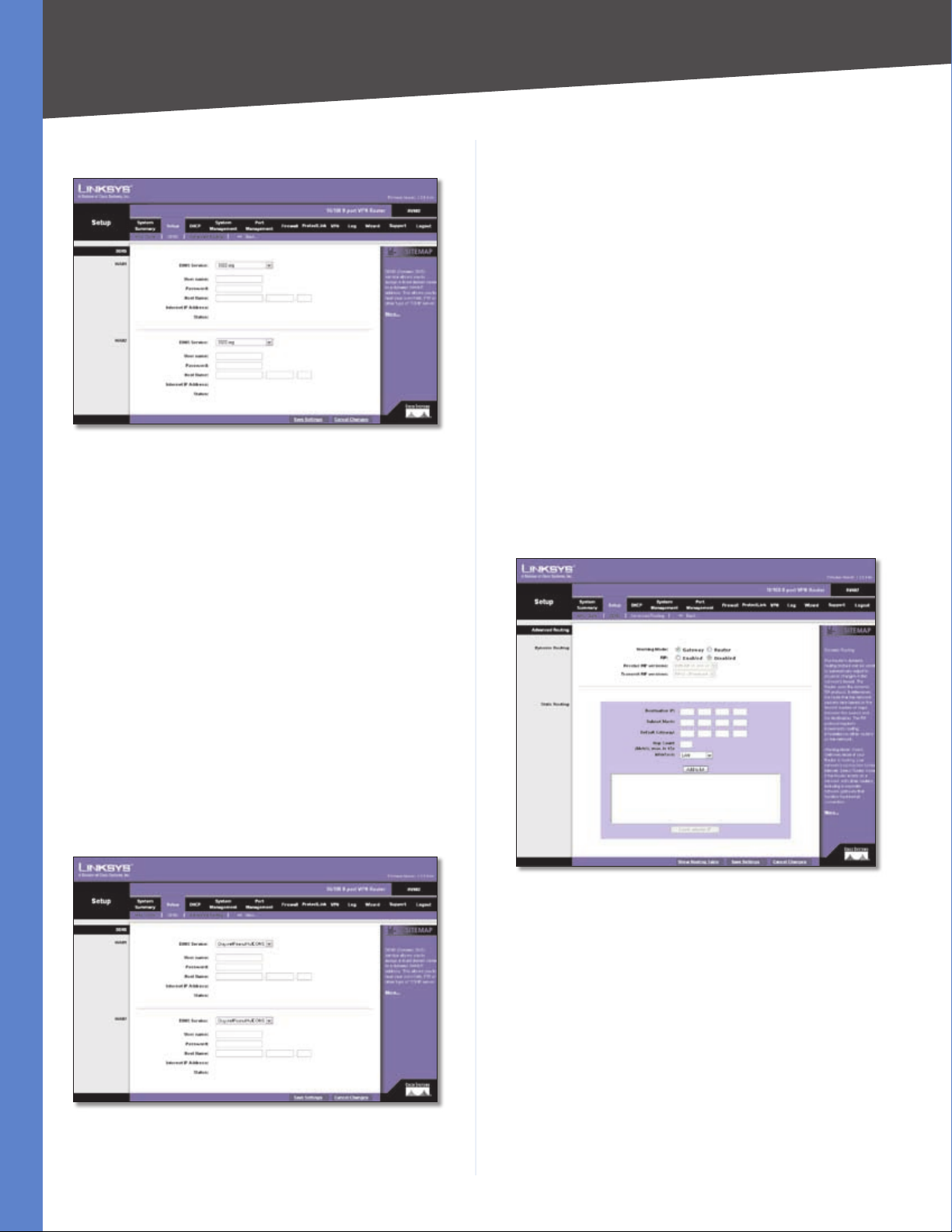
Setup > DDNS
Dynamic Domain Name System (DDNS) service allows
you to assign a fixed domain name to a dynamic WAN IP
address, so you can host your own web, FTP or other type
of TCP/IP server in your LAN. The DDNS feature is disabled
by default.
Before configuring DDNS, visit the website of the
DDNS service you want to use: www.dyndns.org,
www.3322.org, or www.oray.net. Then register a domain
name.
DDNS
WAN1/2
If you have enabled the Dual WAN feature, then you will
have two ports, WAN1 and WAN2, available for DDNS
service.
DDNS Service The DDNS feature is disabled by default.
To enable this feature, select DynDNS.org, 3322.org, or
Oray.net PeanutHull DDNS.
DynDNS.org
Setup > DDNS > DynDNS.org
User name Enter your DynDNS.org account information.
Password Enter your DynDNS.org account information.
Host Name Enter your host name in the three Host Name
fields. For example, if your host name were myhouse.
dyndns.org, then myhouse would go into the first field,
dyndns would go into the second field, and org would go
into the last field.
Custom DNS DynDNS.org offers a free account and a paid
account, which use different authentication methods. If
you have a paid account, select this option to register the
paid account with the DDNS server of DynDNS.org.
Click Save Settings, and the status of the DDNS function
will be updated.
Internet IP Address The Router’s current Internet IP
address is displayed. Because it is dynamic, this will
change.
Status The status of the DDNS function is displayed. If
the status information indicates an error, make sure you
have correctly entered the information for your account
with your DDNS service.
10/100 8-Port VPN Router
19
Page 27
Chapter 4
Advanced Configuration
3322.org
Setup > DDNS > 3322.org
User name Enter your 3322.org account information.
Password Enter your 3322.org account information.
Host Name Enter your host name in the three Host Name
fields. For example, if your host name were myhouse.3322.
org, then myhouse would go into the first field, 3322
would go into the second field, and org would go into the
last field.
Password Enter your PeanutHull account information.
Host Name Enter your host name in the three Host Name
fields. For example, if your host name were myhouse.
oray.net, then myhouse would go into the first field, oray
would go into the second field, and net would go into the
last field.
Click Save Settings, and the status of the DDNS function
will be updated.
Internet IP Address The Router’s current Internet IP
address is displayed. Because it is dynamic, this will
change.
Status The status of the DDNS function is displayed. If
the status information indicates an error, make sure you
have correctly entered the information for your account
with your DDNS service.
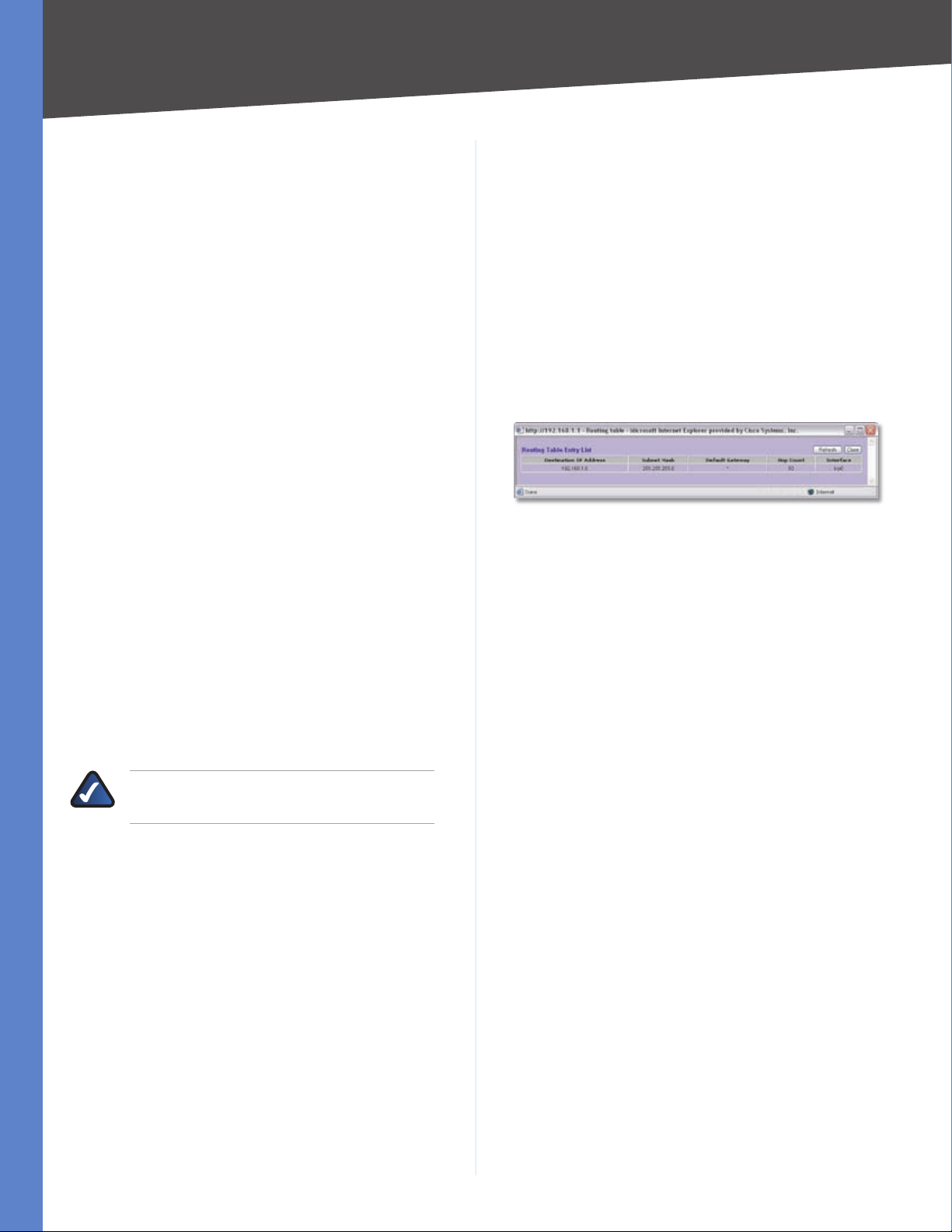
Setup > Advanced Routing
The Advanced Routing screen allows you to configure the
dynamic and static routing settings.
Click Save Settings, and the status of the DDNS function
will be updated.
Internet IP Address The Router’s current Internet IP
address is displayed. Because it is dynamic, this will
change.
Status The status of the DDNS function is displayed. If
the status information indicates an error, make sure you
have correctly entered the information for your account
with your DDNS service.
Oray.net PeanutHull DDNS
Setup > DDNS > Oray.net PeanutHull DDNS
User name Enter your PeanutHull account information.
Setup > Advanced Routing
Advanced Routing
Dynamic Routing
The Router’s dynamic routing feature can be used, so
the Router will automatically adjust to physical changes
in the network’s layout. Using the dynamic RIP protocol,
the Router calculates the most efficient route for the
network’s data packets to travel between the source and
the destination, based upon the shortest paths. The RIP
protocol regularly broadcasts routing information to
other routers on the network. It determines the route that
the network packets take based on the fewest number of
hops between the source and the destination.
10/100 8-Port VPN Router
20
Page 28
Chapter 4
Advanced Configuration
Working Mode Select Gateway mode if the Router
is hosting your network’s connection to the Internet.
Select Router mode if the Router exists on a network
with other routers, including a separate network gateway
that handles the Internet connection. In Router mode,
any computer connected to the Router will not be able
to connect to the Internet unless you have another router
function as the gateway.
RIP (Routing Information Protocol) To use dynamic
routing for communication of network data, select
Enabled. Otherwise, keep the default, Disabled.
Receive RIP versions To use dynamic routing for
reception of network data, select the protocol you want:
None, RIPv1, RIPv2, or Both RIP v1 and v2.
Transmit RIP versions To use dynamic routing for
transmission of network data, select the protocol you want:
None, RIPv1, RIPv2 - Broadcast, or RIPv2 - Multicast.
Static Routing
If the Router is connected to more than one network or
there are multiple routers installed on your network, it
may be necessary to set up static routes. The static routing
function determines the path that data follows over your
network before and after it passes through the Router. You
can use static routing to allow different IP domain users to
access the Internet through the Router.
Static routing is a powerful feature that should be used
by advanced users only. In many cases, it is better to
use dynamic routing because it enables the Router to
automatically adjust to physical changes in the network’s
layout.
NOTE: Static routing is an advanced feature.
Create these routes with care.
To create a static route entry, enter the following
information:
Destination IP Enter the network address of the remote
LAN segment. For a standard Class C IP domain, the
network address is the first three fields of the Destination
LAN IP, while the last field should be 0.
Subnet Mask Enter the subnet mask used on the
destination LAN IP domain. For Class C IP domains, the
subnet mask is 255.255.255.0.
Default Gateway Enter the IP address of the router of the
network, for which this static route is created. For example,
if this network is connected to the local router’s LAN port
through another router, use the WAN IP address of that
router.
passes through before reaching its destination. A node is
any device on the network, such as a computer or router.
Interface Select the appropriate interface. The Interface
tells you whether your network is on the LAN, WAN1, or
WAN2/DMZ. If the gateway router is on a LAN port, then
select LAN. If you are connecting to another network
through the Internet, select the appropriate WAN port
option.
Click Add to List, and configure as many entries as you
would like, up to a maximum of 30. To delete an entry,
select it and click Delete selected IP.
Click Show Routing Table to see the details of your
entries.
Routing Table Entry List
Click Refresh to update the on-screen information. Click
Close to exit this screen and return to the Advanced
Routing screen.
On the Advanced Routing screen, click Save Settings
to save your changes, or click Cancel Changes to undo
them.
DHCP > Setup
The Router can be used as a DHCP (Dynamic Host
Configuration Protocol) server on your network. A DHCP
server automatically assigns available IP addresses to
computers on your network. If you choose to enable the
DHCP server option, all of the computers on your LAN
must be set to obtain an IP address automatically from a
DHCP server. (By default, Windows computers are set to
obtain an IP automatically.)
If the Router’s DHCP server function is disabled, do one of
the following:
Configure the IP address, subnet mask, and DNS •
settings of every computer on your network. (Make
sure you do not assign the same IP address to different
computers.)
Set up a stand-alone DHCP server with the Router as •
the default gateway.
Hop Count Enter the appropriate value (maximum is 15).
This indicates the number of nodes that a data packet
10/100 8-Port VPN Router
21
Page 29
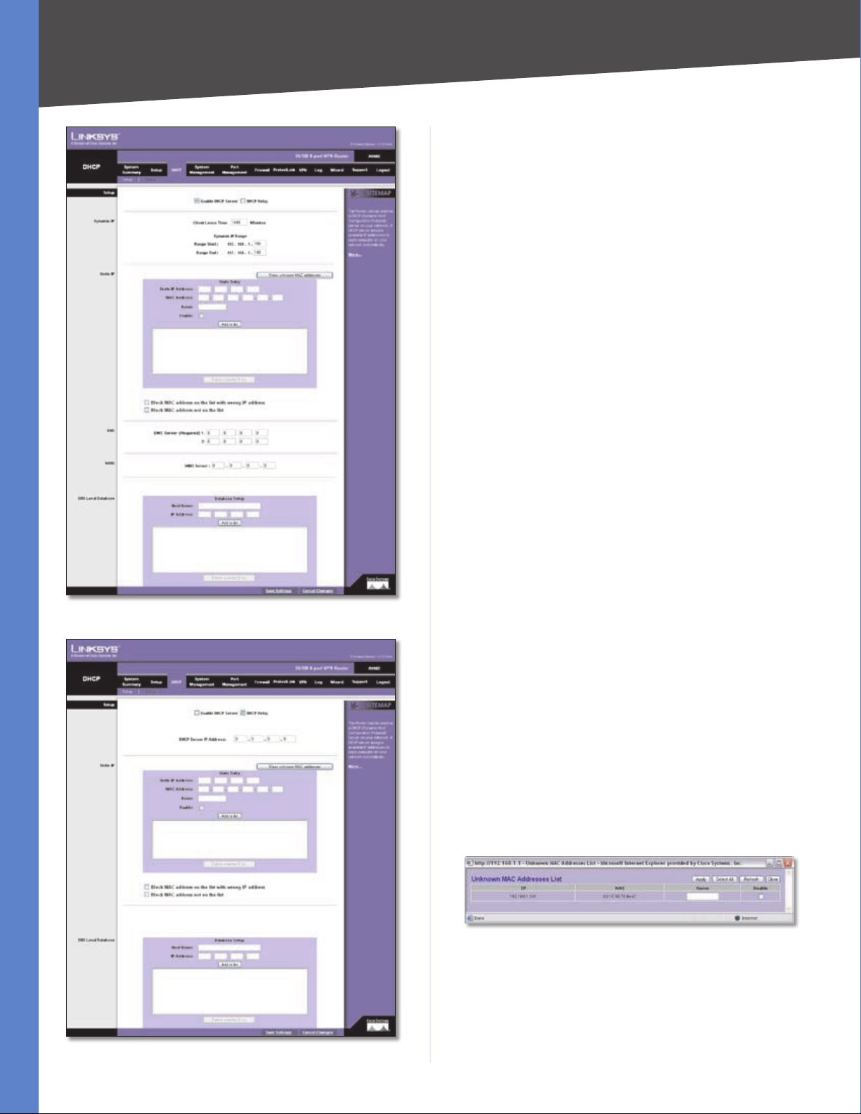
Chapter 4
Advanced Configuration
Setup
Enable DHCP Server To use the Router as your network’s
DHCP server, select Enable DHCP Server. If you already
have a DHCP server on your network, remove the check
mark. Then configure the Dynamic IP settings.
Dynamic IP
Client Lease Time • The Client Lease Time is the amount
of time a network user will be allowed connection to
the Router with their current dynamic IP address. Enter
the amount of time, in minutes, that the user will be
“leased” this dynamic IP address. The range is 5-43,200
minutes. The default is 1440 minutes.
Dynamic IP Range Start/End • Enter a starting IP
address and ending IP address to create a range of
available IP addresses. The default range is 100-149.
(Make sure the Router’s LAN IP address is not in this
dynamic IP range.) For example, if the Router uses the
default LAN IP address, 192.168.1.1, then the starting
value must be 192.168.1.2 or greater.
DHCP > Setup > Enable DHCP Server
DHCP Relay The DHCP Relay mechanism allows DHCP
clients and the DHCP server to be located on different
networks. The DHCP clients will send DHCP discover
broadcast packets to get IP addresses from the DHCP
server, and the Router will act as a DHCP Relay agent and
send DHCP unicast packets to DHCP server. To use the
DHCP Relay function, select DHCP Relay. The DHCP server
function will be automatically disabled. Then configure
the DHCP Server IP Address setting.
DHCP Server IP Address • Enter the IP address of the
DHCP server.
Static IP
You can assign a static IP address to a specific device based
on its MAC address.
Show unknown MAC addresses Click Show unknown
MAC addresses to view all devices’ IP addresses and
corresponding MAC addresses. The Unknown MAC
Addresses List appears.
DHCP > Setup > DHCP Relay
10/100 8-Port VPN Router
Unknown MAC Addresses List
For each device, you can enter a descriptive name in the
Name field. To add an IP address and MAC address set to
the Static IP list, select Enable, and then click Apply. To
add all IP addresses and MAC addresses to the Static IP list,
click Select All.
22
Page 30

Chapter 4
Advanced Configuration
To update the on-screen information, click Refresh. To exit
this screen and return to the Setup screen, click Close.
Static IP Address Enter the static IP address. You can
enter 0.0.0.0 if you want the Router to assign a static IP
address to the device.
MAC Address Enter the MAC address of the device.
Name Enter a descriptive name for the device.
Enable Select Enable to assign the static IP address to
this device.
Click Add to List, and configure as many entries as you
would like, up to a maximum of 100. To delete an entry,
select it and click Delete selected Entry.
Block MAC address on the list with wrong IP address To
block traffic from devices with MAC addresses on the Static
IP list but using the wrong IP addresses, select this option.
It prevents users from changing device IP addresses
without your permission.
Block MAC address not on the list To block traffic from
devices using dynamic IP addresses, select this option. It
blocks all devices with MAC addresses not listed on the
Static IP list.
DNS
This setting is not available if DHCP Relay is enabled.
DNS Server 1-2 You can assign DNS server(s) to the DHCP
clients so the Router will use the DNS server(s) for faster
access to functioning DNS server(s). Enter the IP address
of at least one DNS server.
WINS
This setting is not available if DHCP Relay is enabled.
WINS Server Windows Internet Naming Service (WINS)
is a service that resolves NetBIOS names to IP addresses.
WINS is assigned if the computer (DHCP client) requests
one. If you do not know the IP address of the WINS server,
keep the default, 0.0.0.0.
NOTE: To support NetBIOS for DHCP
clients, the Router uses two methods.
First, when the DHCP clients receive dynamic
IP addresses from the Router, it automatically
includes the information of the WINS server to
support NetBIOS. Second, if a user sets up a static
IP address, then the IP address, subnet mask,
default gateway, and DNS server settings must
be configured on the Internet Protocol (TCP/IP)
screen of the Windows operating system. Then
the WINS IP address must be configured on the
advanced TCP/IP screen. (For more information,
refer to Windows Help.)
DNS Local Database
Use the DNS Local Database mechanism to set up a
DNS database on the Router. The DNS Local Database
performs as an actual DNS server. The database contains
two fields, the Domain Name and IP Address. When a LAN
computer issues a Domain Name request to the Router,
(for example, “help.office”), the Router searches the DNS
Local Database first. If the Router finds the name in the
DNS Local Database, it will reply with the corresponding
IP address to the LAN computer. If the Domain Name is
not found in the DNS Local Database, then the Router will
forward the request to the Internet.
To configure the DNS Local Database, create a list of Host
Name and IP Address mapping entries.
Host Name Enter the Host Name of your entry. The Host
Name must use at least two words and be separated by a
dot “.” (for example, “help.office”). It cannot be entered as
only one word, such as “helpoffice”, because Windows will
automatically append “.com” after the name you enter.
IP Address Enter the IP Address of your entry.
Click Add to List, and configure as many entries as you
would like, up to a maximum of 100. To delete an entry,
select it and click Delete selected Entry.
10/100 8-Port VPN Router
On the Setup screen, click Save Settings to save your
changes, or click Cancel Changes to undo them.
DHCP > Status
On the Status screen, view the status information for the
DHCP server and its clients.
23
Page 31

Chapter 4
DHCP > Status
Status
For the DHCP server, the following information is shown:
DHCP Server This is the IP address of the DHCP server.
Dynamic IP Used It shows the number of dynamic IP
addresses used.
Advanced Configuration
Dual-WAN
Smart Link Backup/Load Balance If you want to use one
of the WAN ports as the primary port and the other WAN
port as backup, then select Smart Link Backup.
If you want the Router to automatically manage the
Internet connection through both WAN ports, then select
Load Balance. The Router will automatically compute the
ratio of the bandwidths of WAN1 and WAN2, and then
it will use Weighted Round Robin (WRR) to balance the
loads of the two WANs.
Proceed to the appropriate section for further
instructions.
Smart Link Backup
Static IP Used It shows the number of static IP addresses
used.
DHCP Available This indicates the number of dynamic IP
addresses available.
Total It shows the total number of dynamic IP addresses
that can be assigned by the DHCP server.
Client Table
For all network clients using the DHCP server, the Client
Table shows the current DHCP Client information:
Client Host Name This is the name assigned to a client
host.
IP Address It is the dynamic IP address assigned to a
client.
MAC Address This indicates the MAC address of a client.
Leased Time It displays the amount of time a network
user will be allowed connection to the Router with their
current dynamic IP address.
Delete Click the Trash Can icon to delete a DHCP client,
and the client host’s IP address will be released.
Click Refresh to update the on-screen information.
System Management > Dual-WAN
There are two functions provided for users, Smart Link
Backup and Load Balance. If you selected DMZ on the
Setup > Network screen, you will not be able to configure
the Dual-WAN settings.
System Management > Dual-WAN > Smart Link Backup
Primary WAN Specify the primary connection, WAN1 or
WAN2.
Network Service Detection
Enable Network Service Detection Network Service
Detection helps manage your connection and can report
when your connection experiences problems. To use this
service, select this option.
Retry Count Enter the number of times the Router will
try to reconnect if the connection fails.
Retry Timeout Enter the number of times the Router will
try to make a connection to your ISP before it times out.
When Fail Should the connection be lost, set the Router
to perform one of the following actions, Remove the
Connection or Generate the Error Condition in the
System Log.
Remove the Connection • Failover will occur; the
backup will be used. When the primary WAN port’s
connectivity is restored, the backup WAN port will
return to standby mode.
10/100 8-Port VPN Router
24
Page 32

Chapter 4
Advanced Configuration
Generate the Error Condition in the System •
Log Failover will not occur; only an error condition
will be logged.
Network Service Detection can test a WAN port’s network
connectivity by pinging the Default Gateway or a specific
IP address.
WAN1/2
Default Gateway Select this option to ping the Default
Gateway.
ISP Host Select this option to ping the ISP Host. Then
enter the IP address.
Remote Host Select this option to ping the Remote Host.
Then enter the IP address.
DNS Lookup Host Select this option to ping the DNS
Lookup Host. Then enter the IP address.
Click Save Settings to save your changes, or click Cancel
Changes to undo them.
Load Balance
Retry Count Enter the number of times the Router will
try to reconnect if the connection fails.
Retry Timeout Enter the number of times the Router will
try to make a connection to your ISP before it times out.
When Fail Should the connection not be reestablished,
set the Router to perform one of the following actions,
Remove the Connection or Generate the Error
Condition in the System Log.
Network Service Detection can test this connection by
pinging the Default Gateway or a specific IP address.
WAN1/2
Default Gateway Select this option to ping the Default
Gateway.
ISP Host Select this option to ping the ISP Host. Then
enter the IP address.
Remote Host Select this option to ping the Remote Host.
Then enter the IP address.
DNS Lookup Host Select this option to ping the DNS
Lookup Host. Then enter the IP address.
Bandwidth
System Management > Dual-WAN > Load Balance
Network Service Detection
WAN1/2
Upstream Enter the maximum upstream bandwidth
provided by your ISP. The default is 512 kbit/sec.
Downstream Enter the maximum downstream
bandwidth provided by your ISP. The default is
512 kbit/sec.
Protocol Binding
Service Select the Service you want.
If the Service you need is not listed in the menu, click
Service Management to add the new service. The Service
Management screen appears.
Enable Network Service Detection Network Service
Detection helps manage your connection and can report
when your connection experiences problems. To use this
service, select this option.
10/100 8-Port VPN Router
Service Management
25
Page 33

Chapter 4
Service Name Enter a name. For IP Binding only, select
All.
Protocol Select the protocol it uses.
Port Range Enter its range.
Click Add to List. Click Save Settings to save your changes,
or click Cancel Changes to undo them. Click Exit to return
to the Dual-WAN screen.
If you want to modify a service you have created, select it
and click Update this service. Make changes. Click Save
Settings to save your changes, or click Cancel Changes to
undo them. Click Exit to return to the Dual-WAN screen.
If you want to delete a service you have created, select it
and click Delete selected service. Click Save Settings
to save your changes, or click Cancel Changes to undo
them. Click Exit to return to the Dual-WAN screen.
Source IP Enter the source IP address or range. If you
need Service Binding only, then you can keep the default,
which is 0.
Advanced Configuration
System Management > Bandwidth Management > Rate Control
Destination IP Enter the destination IP address or range.
If you need Service Binding only, then you can keep the
default, which is 0.
Interface Select the appropriate WAN interface, WAN1
or WAN2.
Enable Select Enable to use this Protocol Binding rule.
Click Add to List, and configure as many rules as you
would like, up to a maximum of 100. To delete a rule, select
it and click Delete selected application.
Click Save Settings to save your changes, or click Cancel
Changes to undo them.
System Management > Bandwidth Management
Quality of Service (QoS) features let you control how
the Router manages network traffic. With Bandwidth
Management (Layer 3), the Router can provide better
service to selected types of network traffic. There are two
types of functionality available, and only one type can
work at one time. Rate Control functionality is for minimum
(guaranteed) bandwidth and maximum bandwidth by
service or IP address, while Priority functionality is for
services. Both types can control inbound or outbound
traffic.
Bandwidth Management
The Maximum Bandwidth provided by ISP
WAN1/2
Upstream Enter the maximum upstream bandwidth
provided by your ISP. The default is 512 kbit/sec.
Downstream Enter the maximum downstream
bandwidth provided by your ISP. The default is
512 kbit/sec.
Bandwidth Management Type
Type Select the type of functionality you want to use,
Rate Control or Priority. Rate Control functionality is
for minimum (guaranteed) bandwidth and maximum
(limited) bandwidth by service or IP address, while
Priority functionality is for services. Then proceed to the
instructions for the type you selected.
Rate Control
Interface Select the appropriate WAN interface, WAN1
or WAN2.
Service Select the Service you want.
If the Service you need is not listed in the menu, click
Service Management to add the new service. The Service
Management screen appears.
10/100 8-Port VPN Router
26
Page 34

Chapter 4
Service Management
Service Name Enter a name.
Protocol Select the protocol it uses.
Port Range Enter its range.
Advanced Configuration
Summary (Rate Control Selected)
To change a rule, click Edit. To update the list, click
Refresh. To return to the Bandwidth Management screen,
click Close.
On the Bandwidth Management screen, click Save Settings
to save your changes, or click Cancel Changes to undo
them.
Priority
Click Add to List. Click Save Settings to save your changes,
or click Cancel Changes to undo them. Click Exit to return
to the Bandwidth Management screen.
If you want to modify a service you have created, select it
and click Update this service. Make changes. Click Save
Settings to save your changes, or click Cancel Changes
to undo them. Click Exit to return to the Bandwidth
Management screen.
If you want to delete a service you have created, select it
and click Delete selected service. Click Save Settings
to save your changes, or click Cancel Changes to undo
them. Click Exit to return to the Bandwidth Management
screen.
IP Enter the IP address or range you need to control. To
include all internal IP addresses, keep the default, 0.
Direction Select Upstream for outbound traffic, or select
Downstream for inbound traffic.
Min. Rate Enter the minimum rate for the guaranteed
bandwidth.
Max. Rate Enter the maximum rate for the maximum
bandwidth.
Enable Select Enable to use this Rate Control rule.
System Management > Bandwidth Management > Priority
Interface Select the appropriate WAN interface, WAN1
or WAN2.
Service Select the Service you want.
If the Service you need is not listed in the menu, click
Service Management to add the new service. The Service
Management screen appears.
Click Add to List, and configure as many rules as you
would like, up to a maximum of 100. To delete a rule, select
it and click Delete selected application.
Click Summary to see a summary of the Rate Control
rules.
10/100 8-Port VPN Router
27
Page 35

Chapter 4
Service Management
Service Name Enter a name.
Protocol Select the protocol it uses.
Port Range Enter its range.
Advanced Configuration
To change a rule, click Edit. To update the list, click
Refresh. To return to the Bandwidth Management screen,
click Close.
On the Bandwidth Management screen, click Save Settings
to save your changes, or click Cancel Changes to undo
them.
System Management > SNMP
SNMP, or Simple Network Management Protocol, is a
network protocol that provides network administrators
with the ability to monitor the status of the Router and
receive notification of any critical events as they occur on
the network. The Router supports SNMP v1/v2c and all
relevant Management Information Base II (MIBII) groups.
The appliance replies to SNMP Get commands for MIBII via
any interface and supports a custom MIB for generating
trap messages.
Click Add to List. Click Save Settings to save your changes,
or click Cancel Changes to undo them. Click Exit to return
to the Bandwidth Management screen.
If you want to modify a service you have created, select it
and click Update this service. Make changes. Click Save
Settings to save your changes, or click Cancel Changes
to undo them. Click Exit to return to the Bandwidth
Management screen.
If you want to delete a service you have created, select it
and click Delete selected service. Click Save Settings
to save your changes, or click Cancel Changes to undo
them. Click Exit to return to the Bandwidth Management
screen.
Direction Select Upstream for outbound traffic, or select
Downstream for inbound traffic.
Priority Select High, Middle, or Low. High priority
services will share 30% of the total system bandwidth.
Middle priority services will share 60% of the total system
bandwidth. Low priority services will share 10% of the
total bandwidth. The default is Middle.
Enable Select Enable to use this Priority rule.
Click Add to List, and configure as many rules as you
would like, up to a maximum of 50. To delete a rule, select
it and click Delete selected application.
System Management > SNMP
SNMP Enable SNMP is enabled by default. To disable the
SNMP agent, click this option to remove the check mark.
System Name Set the hostname for the Router.
System Contact Enter the name of the network
administrator who can be contacted with updates about
the Router.
System Location Enter the network administrator’s
contact information: an e-mail address, telephone number,
or pager number.
Get Community Name Create the name for a group
or community of administrators who can view SNMP
data. The default is public. A name of no more than 64
alphanumeric characters long must be entered.
Click Summary to see a summary of the Priority rules. The
Summary screen appears.
Summary (Priority Selected)
10/100 8-Port VPN Router
Set Community Name Create the name for a group or
community of administrators who can receive SNMP
traps, messages regarding the Router’s status. A name of
no more than 64 alphanumeric characters long must be
entered.
Trap Community Name Create the password that will
be sent with each trap to the SNMP manager. A name of
28
Page 36

Chapter 4
Advanced Configuration
no more than 64 alphanumeric characters long must be
entered.
Send SNMP Trap to Enter the IP address or domain name
that should receive the traps sent by the Router.
Click Save Settings to save your changes, or click Cancel
Changes to undo them.
System Management > Diagnostic
The Router has two built-in tools, DNS Name Lookup
and Ping, which are used for troubleshooting network
problems.
The Internet has a service called the Domain Name Service
(DNS), which allows users to enter an easily remembered
host name, such as www.linksys.com, instead of numerical
TCP/IP addresses to access Internet resources. The DNS
Name Lookup tool will return the numerical TCP/IP address
of a host name.
The ping test bounces a packet off a machine on the
Internet back to the sender. This test shows if the Router
is able to contact the remote host. If users on the LAN
are having problems accessing services on the Internet,
try pinging the DNS server or other machine at the ISP’s
location. If this test is successful, try pinging devices
outside the ISP. This will show if the problem lies with the
ISP’s connection.
message.) The Router will then query the DNS server and
display the results.
Name The host name is displayed.
Address The URL of the host is displayed.
Ping
Before using this tool make sure you know the device or
host’s IP address. If you do not know it, use the Router’s
DNS Name Lookup tool to find the IP address.
System Management > Diagnostic > Ping
Ping host or IP address Enter the IP address of the device
being pinged, and click Go. The test will take a few seconds
to complete. Then the Router will display the results.
Status The status of the ping test is displayed.
Diagnostic
DNS Name Lookup/Ping Select which tool you want
to use, DNS Name Lookup or Ping. Then proceed to the
appropriate instructions.
DNS Name Lookup
Before using this tool, make sure the IP address of the DNS
server is entered on the Setup > Network screen; otherwise,
this tool will not work.
System Management > Diagnostic > DNS Name Lookup
Look up the name Enter the host name, and click Go.
(Do not add the prefix http:// or else you will get an error
Packets The number of packets transmitted, number
of packets received, and percentage of packets lost are
displayed.
Round Trip Time The minimum, maximum, and average
round trip times are displayed.
System Management > Factory Default
Use this screen to clear all of your configuration information
and restore the Router to its factory default settings. Only
use this feature if you wish to discard all the settings and
preferences that you have configured.
System Management > Factory Default
10/100 8-Port VPN Router
29
Page 37

Chapter 4
Advanced Configuration
Factory Default
Return to Factory Default Setting Click Return to
Factory Default Setting if you want to restore the Router
to its factory default settings. After clicking the button, a
confirmation screen appears. Click OK to continue.
Factory Default Confirmation
System Management > Firmware Upgrade
You can use this feature to upgrade the Router’s firmware
to the latest version.
Extract the file on your computer. Then follow the Firmware
Upgrade instructions.
System Management > Restart
If you need to restart the Router, Linksys recommends that
you use the Restart tool on this screen. When you restart
from the Restart screen, then the Router will send out your
log file before it is reset.
System Management > Restart
Restart
Restart Router Click Restart Router to restart the Router.
After clicking the button, a confirmation screen appears.
Click OK to continue.
System Management > Firmware Upgrade
Firmware Upgrade
To download the firmware, refer to the Firmware Download
instructions. If you have already downloaded the firmware
onto your computer, then click the Browse button to look
for the extracted file.
Firmware Upgrade Right Now After you have selected
the extracted file, click Firmware Upgrade Right Now.
NOTE: The Router will take approximately ten
minutes to upgrade its firmware. During this
process, do not power off the Router or press
the Reset button.
Firmware Download
Firmware Download from Linksys Web Site If you need
to download the latest version of the Router’s firmware,
click Firmware Download from Linksys Web Site. The
Support page of the Linksys website appears.
Follow the on-screen instructions to access the Downloads
page for the 10/100 8-Port VPN Router (model number:
RV082). Then download the firmware upgrade file.
Restart Confirmation
Active Firmware Version By default, the current firmware
version is selected.
Backup Firmware Version You can restart the Router
using a previous firmware version; however, all custom
settings will be reset to their factory defaults. (If you want
to save your custom settings before the restart, use the
Setting Backup screen.) To use the previous firmware
version for the restart, select Backup Firmware Version.
System Management > Setting Backup
This screen allows you to make a backup file of your
preferences file for the Router. To save the backup file, you
need to export the configuration file.
To use the backup preferences file, you need to import the
configuration file that you previously exported.
10/100 8-Port VPN Router
30
Page 38

Chapter 4
Advanced Configuration
System Management > Setting Backup
Import Configuration File
To import a configuration file, first specify where your
backup preferences file is located. Click Browse, and then
select the appropriate configuration file.
Import After you select the file, click Import. This process
may take up to a minute. Then restart the Router so that
the changes will take effect.
Export Configuration File
Export To export the Router’s current configuration file,
click Export.
Port Management > Port Setup
Basic Per Port Config.
The Basic Per Port Config. table displays the following:
Port ID The port number or name is displayed.
Interface The port’s interface type, LAN or WAN1/2, is
displayed.
Disable To disable a port, select Disable.
Priority For port-based QoS, select the appropriate
priority level, High or Normal.
Speed Select the port speed, 10M or 100M.
Duplex Select the duplex mode, Half or Full.
Auto Neg. Select Enable if you want the Router’s ports
to auto-negotiate connection speeds and duplex mode;
then you will not need to set up speed and duplex settings
separately.
VLAN For each LAN port, a VLAN (a Virtual LAN, or
network within your network) can be established. Up to
eight VLANs can be established.
File Download
Click Save, and then select the location where you want
to store your backup preferences file. By default, this file
will be called RV082.exp, but you may rename it if you
wish. This process may take up to a minute.
Port Management > Port Setup
Configure the connection settings for each local port,
such as priority, speed, and duplex. You can also enable or
disable the auto-negotiation feature for all ports.
10/100 8-Port VPN Router
Click Save Settings to save your changes, or click Cancel
Changes to undo them.
Port Management > Port Status
Status information is displayed for the selected port.
31
Page 39

Chapter 4
Port Management > Port Status
Port ID To see the status information and settings for a
specific port, select its ID number or name.
Advanced Configuration
To update the on-screen information, click Refresh.
Firewall > General
Enable or disable a variety of firewall, security, and web
features.
Port Status
Summary
For the selected port, the Summary table displays the
following:
Type The port type is displayed.
Interface The interface type, LAN or WAN, is displayed.
Link Status The status of the connection is displayed.
Port Activity The status of the port is displayed.
Speed Status The speed of the port, 10 Mbps, or 100
Mbps, is displayed.
Duplex Status The duplex mode is displayed, Half or
Full.
Auto negotiation The status of the feature is displayed.
VLAN The VLAN of the port is displayed.
Statistics
For the selected port, the Statistics table displays the
following:
Port Receive Packet Count The number of packets
received is displayed.
Port Receive Packet Byte Count The number of packet
bytes received is displayed.
Port Transmit Packet Count The number of packets
transmitted is displayed.
Port Transmit Packet Byte Count The number of packet
bytes transmitted is displayed.
Port Packet Error Count The number of packet errors is
displayed.
Firewall > General
General
Firewall The firewall is enabled by default. If you disable
it, then the SPI, DoS, and Block WAN Request features,
Access Rules, and Content Filters will also be disabled, and
the Remote Management feature will be enabled.
SPI (Stateful Packet Inspection) This option is enabled
by default. The Router’s firewall uses Stateful Packet
Inspection to review the information that passes through
the firewall. It inspects all packets based on the established
connection, prior to passing the packets for processing
through a higher protocol layer.
DoS (Denial of Service) This option is enabled by default.
It protects internal networks from Internet attacks, such
as SYN Flooding, Smurf, LAND, Ping of Death, IP Spoofing,
and reassembly attacks.
Block WAN Request This option is enabled by default.
Using this feature, the Router drops both unaccepted TCP
request and ICMP packets from the WAN side. Hackers will
not find the Router by pinging the WAN IP address.
Remote Management This option is disabled by
default. If you want to manage the Router through a WAN
connection, first change the password on the Setup >
Password screen (this prevents any user from accessing
the Router with the default password). Then select Enable
10/100 8-Port VPN Router
32
Page 40

Chapter 4
Advanced Configuration
for the Remote Management setting, and enter the port
number (port 80, the default, or 8080 is usually used).
NOTE: If the Remote Management feature on
the Firewall > General screen has been enabled,
then users with administrative privileges can
remotely access the web-based utility. Use
http://<WAN IP address of the Router>, or
use https://<WAN IP address of the Router> if
you have enabled the HTTPS feature.
HTTPS HTTPS is a secured HTTP session. If Remote
Management is enabled, HTTPS is enabled by default.
NOTE: If you disable the HTTPS feature, then
you also disable the Linksys QuickVPN service
on the Router.
Multicast Pass Through This option is disabled by default.
IP multicasting occurs when a single data transmission
is sent to multiple recipients at the same time. Using
this feature, the Router allows IP multicast packets to be
forwarded to the appropriate LAN devices. Multicast Pass
Through is used for Internet games, videoconferencing,
and multimedia applications.
Restrict WEB Features
Block Select the filters you want to use.
Java • Java is a programming language for websites. If
you deny Java applets, you run the risk of losing access
to Internet sites created using this programming
language. To block Java applets, select Java.
Cookies • A cookie is data stored on your PC and used
by Internet sites when you interact with them. To block
cookies, select Cookies.
ActiveX • ActiveX is a programming language for
websites. If you deny ActiveX, you run the risk of losing
access to Internet sites created using this programming
language. To block ActiveX, select ActiveX.
Click Save Settings to save your changes, or click Cancel
Changes to undo them.
Firewall > Access Rules
Access rules evaluate network traffic to decide whether
or not it is allowed to pass through the Router’s firewall.
Access Rules look specifically at a data transmission’s
source IP address, destination IP address, and IP protocol
type, and you can apply each access rule according to a
different schedule.
With the use of custom rules, it is possible to disable all
firewall protection or block all access to the Internet, so
use extreme caution when creating or deleting access
rules.
The Router has the following default rules:
All traffic from the LAN to the WAN is allowed. •
All traffic from the WAN to the LAN is denied. •
All traffic from the LAN to the DMZ is allowed. •
All traffic from the DMZ to the LAN is denied. •
All traffic from the WAN to the DMZ is allowed. •
All traffic from the DMZ to the WAN is allowed. •
Custom rules can be created to override the above default
rules, but there are four additional default rules that will
be always active and cannot be overridden by any custom
rules.
HTTP service from the LAN to the Router is always •
allowed.
DHCP service from the LAN is always allowed. •
DNS service from the LAN is always allowed. •
Ping service from the LAN to the Router is always •
allowed.
Access to HTTP Proxy Servers • Use of WAN proxy
servers may compromise the Router’s security. If you
block access to HTTP proxy servers, then you block
access to WAN proxy servers. To block access, select
Access to HTTP Proxy Servers.
Don’t block Java/ActiveX/Cookies/Proxy to Trusted
Domains To keep trusted sites unblocked, select this
option.
Add Enter the domain you want to block.
To add a domain to the list, click Add to list. To remove a
domain from the list, select the entry, and click the Delete
selected domain.
10/100 8-Port VPN Router
Firewall > Access Rules
33
Page 41

Chapter 4
Advanced Configuration
Access Rules
Except for the default rules, all configured access rules
are listed in the Access Rules table, and you can set the
priority for each custom rule.
If the Access Rules table has multiple pages, select a
different page to view from the Jump to drop-down menu.
If you want more or fewer entries listed per page, select
a different number from the entries per page drop-down
menu.
For each access rule, the Access Rules table lists the
following:
Priority The priority of the access rule is displayed, 1
indicating the highest priority. To change its priority, select
a different priority from the drop-down menu. (When an
access rule is created, the Router automatically assigns a
priority; however, you can change the priority after the
rule is created.) If there is a conflict between two access
rules, then the higher priority rule takes precedence. The
default access rules have the lowest priority.
Enable The status of the access rule is displayed. To
enable or disable a rule, click the Enable check box.
Action The Action, Allow or Deny, is displayed.
Service The Service is displayed.
Source Interface The Source Interface, LAN or WAN1/2,
is displayed.
Source The specific Source is displayed.
Add a New Access Rule
Add a New Access Rule
Services
Wizard If you need help to configure the access rules,
click Wizard, and follow the on-screen instructions. For
additional information, refer to the “Wizard” section of this
chapter.
Action Select Allow or Deny, depending on the purpose
of the access rule.
Service Select the Service you want.
If the Service you need is not listed in the menu, click
Service Management to add the new service. The Service
Management screen appears.
Destination The specific Destination is displayed.
Time The time interval to which the access rule applies
is displayed.
Day The days to which the access rule applies is
displayed.
Click Edit to edit an access rule, or click the Trash Can icon
to delete an access rule.
Click Add New Rule to add new access rules, and the Add
a New Access Rule screen appears.
Click the Restore to Default Rules to restore the default
rules and delete the custom access rules.
Service Management
Service Name Enter a name.
Protocol Select the protocol it uses.
Port Range Enter its range.
Click Add to List. Click Save Settings to save your changes,
or click Cancel Changes to undo them. Click Exit to return
to the Add a New Access Rule screen.
If you want to modify a service you have created, select it
and click Update this service. Make changes. Click Save
10/100 8-Port VPN Router
34
Page 42

Chapter 4
Advanced Configuration
Settings to save your changes, or click Cancel Changes
to undo them. Click Exit to return to the Add a New Access
Rule screen.
If you want to delete a service you have created, select it
and click Delete selected service. Click Save Settings to
save your changes, or click Cancel Changes to undo them.
Click Exit to return to the Add a New Access Rule screen.
Log The Router can keep a log tracking this type of
activity. To keep a log, select Log packets match this
access rule. If you do not want a log, select Do Not Log
these packets.
NOTE: If the Deny Policies option is enabled on
the Log > System Log screen, then the log will
not include log events from the Deny access
rules on the Firewall > Access Rules screen.
Log events from the Deny access rules will be
logged separately from Deny Policies if the
option, Log packets match this rule, is selected.
If the Allow Policies option is enabled on the
Log > System Log screen, then the log will
include log events from the Allow access rules
on the Firewall > Access Rules screen, regardless
of the option, Log packets match this rule.
Firewall > Content Filter
Use this screen to block specific domains during the
designated days and times for specific devices.
Firewall > Content Filter
Source Interface Select WAN1, WAN2, LAN, or Any.
Source IP Select the Source IP address(es) for the access
rule. If it can be any IP address, select Any. If it is one IP
address, select Single and enter the IP address. If it is a
range of IP addresses, select Range, and enter the starting
and ending IP addresses in the fields provided.
Destination IP Select the Destination IP address(es) for
the access rule. If it can be any IP address, select Any. If it
is one IP address, select Single and enter the IP address.
If it is a range of IP addresses, select Range, and enter the
starting and ending IP addresses in the fields provided.
Scheduling
Apply this rule Decide when you want the access rule to
be enforced. To specify days of the week, select 24 Hr, and
then select the appropriate days.
To specify specific hours, select from, and enter the
specific hours and minutes in 24-hour format. Then select
the appropriate days.
The default for any new rule is to always enforce it.
Click Save Settings to save your changes, or click Cancel
Changes to undo them. Click Return to return to the
Access Rules screen.
Content Filter
Forbidden Domains
Block Forbidden Domains To block access to the
websites on the Forbidden Domains list, select this
option.
Add Enter the domain you want to block.
To add a domain to the list, click Add to list. To remove a
domain from the list, select the entry, and click the Delete
selected domain.
Website Blocking by Keywords
Enable Website Blocking by Keywords To block access
to websites using the keywords on the Website Blocking
by Keywords list, select this option.
Add Enter the keyword you want to block.
To add a keyword to the list, click Add to list. To remove a
domain from the list, select the entry, and click the Delete
selected keywords.
Scheduling Decide when you want the content filters
rules to be enforced. To specify specific hours, select
from, and enter the specific hours and minutes in 24-hour
format. Then select the appropriate days.
10/100 8-Port VPN Router
The default is to always enforce it.
35
Page 43

Chapter 4
Advanced Configuration
Click Save Settings to save your changes, or click Cancel
Changes to undo them.
NOTE: The content filter rules will be
automatically disabled if the Trend Micro
ProtectLink service is activated on the Router.
ProtectLink
For information about the ProtectLink tab, refer to
“Appendix G: Trend Micro ProtectLink Gateway Service”.
VPN > Summary
This screen displays general information about the
Router’s VPN tunnel settings. The Router supports up to
100 tunnels.
For each VPN tunnel, the No., Name, Status, Phase 2 Enc/
Auth/Grp, Local Group, Remote Group, and Remote
Gateway will be displayed.
For each group VPN, the Group Name, number of
Connected Tunnels, Phase 2 Encrypt/Auth/Group, Local
Group, and Remote Client will be displayed.
Click Close to exit this screen and return to the Summary
screen.
Tunnel Status
Add New Tunnel Click Add New Tunnel to add a VPN
tunnel. The Mode Choose screen appears.
VPN > Summary
Summary
Tunnel Used The number of VPN tunnels being used is
displayed.
Tunnel Available The number of available VPN tunnels
is displayed.
Detail Click Detail for more information.
VPN Summary Details
The WAN1 IP address and WAN2 IP address will be
displayed.
Mode Choose
Gateway to Gateway
To create a tunnel between two VPN devices, such as two
VPN Routers, click Add Now. The Gateway to Gateway
screen appears. Proceed to the “VPN > Gateway to
Gateway” section for instructions. Click Return to return
to the Summary screen.
Client to Gateway
To create a tunnel between the VPN Router and the client
using VPN client software that supports IPSec, click Add
Now. The Client to Gateway screen appears. Proceed to the
“VPN > Client to Gateway” section for instructions. Click
Return to return to the Summary screen.
If the VPN Summary table has multiple pages, select a
different page to view from the Jump to drop-down menu.
If you want more or fewer entries listed per page, select
a different number from the entries per page drop-down
menu.
After you have added the VPN tunnel, you will see it listed
in the table.
10/100 8-Port VPN Router
No. It shows the number of the VPN tunnel.
36
Page 44

Chapter 4
Advanced Configuration
Name It shows the Tunnel Name that you gave the VPN
tunnel.
Status This indicates the status of the VPN tunnel.
Phase2 Enc/Auth/Grp This shows the Phase 2
Encryption type (NULL/DES/3DES/AES-128/AES-192/
AES-256), Authentication method (NULL/MD5/SHA1),
and DH Group number (1/2/5) that you chose in the IPSec
Setup section.
If you selected Manual for the Keying Mode in the IPSec
section, then only the Encryption type and Authentication
method will be displayed.
Local Group This shows the IP address and subnet mask
of the Local Group.
Remote Group The IP address and subnet mask of the
Remote Group are displayed here.
Remote Gateway It shows the IP address of the Remote
Gateway.
Tunnel Test Click Connect to verify the status of the
VPN tunnel. The test result will be updated in the Status
column. If the tunnel is connected, a Disconnect button
will be available so you can end the connection.
Config. Click Edit to open a new screen where you
can change the tunnel’s settings. Refer to the “Gateway
to Gateway” or “Client to Gateway” section for more
information. Click the Trash Can icon to delete all of your
tunnel settings for each individual tunnel.
Tunnel Enabled The number of enabled VPN tunnels is
displayed.
Tunnel Defined The number of defined VPN tunnels is
displayed.
Remote Clients Status Click Detail List to display the
Group Name, IP address and Connection Time of this group
VPN. Click Refresh to update the on-screen information.
Click Close to exit this screen and return to the Summary
screen.
Tunnel Test Click Connect to verify the status of the
group VPN. The test result will be updated in the Status
column. If the group VPN is connected, a Disconnect
button will be available so you can end the connection.
Config. Click Edit to open a new screen where you
can change the tunnel’s settings. Refer to the “Client to
Gateway” section for more information. Click the Trash
Can icon to delete all of your settings for each individual
group VPN.
VPN Clients Status
This section identifies the VPN clients currently connected
to the Router.
No. It shows the number of the VPN client.
Username It shows the name of the VPN client.
Status This indicates the status of the VPN client
connection.
Start Time This shows the time when the VPN client
established its VPN connection to the Router.
End Time This shows the time when the VPN client ended
its VPN connection to the Router.
Duration This shows how long the VPN connection
existed.
To disconnect any VPN client, select the VPN client in the
Disconnect column, and then click Disconnect.
GroupVPN Status
If you do not enable the GroupVPN setting for any of your
Client to Gateway tunnels, then this section will be blank.
Group Name This shows the name you entered when
you created the Client to Gateway tunnel.
Connected Tunnels This shows the number of users
logged into the group VPN.
Phase2 Enc/Auth/Grp This shows the Phase 2
Encryption type (NULL/DES/3DES/AES-128/AES-192/AES-
256), Authentication method (NULL/MD5/SHA1), and DH
Group number (1/2/5) that you chose in the IPSec Setup
section.
Local Group This shows the IP address and subnet mask
of the Local Group.
Remote Client This shows the remote clients in the
group VPN.
10/100 8-Port VPN Router
VPN > Gateway to Gateway
Use this screen to create a new tunnel between two VPN
devices.
37
Page 45

Chapter 4
Advanced Configuration
IP Only
The default is IP Only. Only the device with a specific IP
address will be able to access the tunnel.
Local Security Gateway Type > IP Only
IP address The WAN (or Internet) IP address of the Router
automatically appears.
IP + Domain Name(FQDN) Authentication
The IP address and FQDN must match the Remote Security
Gateway of the remote VPN device, and they can only be
used for one tunnel connection.
VPN > Gateway to Gateway
Add a New Tunnel
Tunnel No The tunnel number is automatically
generated.
Tunnel Name Enter a name for this VPN tunnel, such as
Los Angeles Office, Chicago Branch, or New York Division.
This allows you to identify multiple tunnels and does not
have to match the name used at the other end of the
tunnel.
Interface Select the appropriate WAN port, WAN1 or
WAN2 (available if the Dual WAN feature is enabled).
Enable Check this box to enable a VPN tunnel. (When
you create a VPN tunnel, this check box will be disabled.)
Local Group Setup
Local Security Gateway Type
Select the type you want to use: IP Only, IP + Domain
Name(FQDN) Authentication, IP + E-mail Addr.(USER
FQDN) Authentication, Dynamic IP + Domain
Name(FQDN) Authentication, or Dynamic IP + Email Addr.(USER FQDN) Authentication. Follow the
instructions for the type you want to use.
NOTE: The Local Security Gateway Type you
select should match the Remote Security
Gateway Type selected on the VPN device at the
other end of the tunnel.
Local Security Gateway Type > IP + Domain Name(FQDN)
Authentication
Domain Name The Fully Qualified Domain Name (FQDN)
is the host name and domain name for a specific computer
on the Internet. Enter the FQDN of the Router.
IP address The WAN (or Internet) IP address of the Router
automatically appears.
IP + E-mail Addr.(USER FQDN) Authentication
Local Security Gateway Type > IP + E-mail Addr.(USER FQDN)
Authentication
E-mail address Enter the e-mail address for
authentication.
IP address The WAN (or Internet) IP address of the Router
automatically appears.
Dynamic IP + Domain Name(FQDN) Authentication
The Local Security Gateway will be a dynamic IP address,
so you do not need to enter the IP address. When the
Remote Security Gateway requests to create a tunnel with
the Router, the Router will work as a responder.
The domain name must match the Remote Security
Gateway of the remote VPN device and can only be used
for one tunnel connection.
10/100 8-Port VPN Router
38
Page 46

Chapter 4
Advanced Configuration
Local Security Group Type > Subnet
Local Security Gateway Type > Dynamic IP + Domain Name(FQDN)
Authentication
Domain Name Enter the domain name for authentication.
(Once used, you cannot use it again to create a new tunnel
connection.)
Dynamic IP + E-mail Addr.(USER FQDN) Authentication
The Local Security Gateway will be a dynamic IP address,
so you do not need to enter the IP address. When the
Remote Security Gateway requests to create a tunnel with
the Router, the Router will work as a responder.
Local Security Gateway Type > Dynamic IP + E-mail Addr.(USER FQDN)
Authentication
E-mail address Enter the e-mail address for
authentication.
Local Security Group Type
Select the local LAN user(s) behind the Router that can
use this VPN tunnel. Select the type you want to use: IP,
Subnet, or IP Range. Follow the instructions for the type
you want to use.
NOTE: The Local Security Group Type you select
should match the Remote Security Group Type
selected on the VPN device at the other end of
the tunnel.
After you have selected the Local Security Group Type, the
settings available on this screen may change, depending
on which selection you have made.
IP
Only the computer with a specific IP address will be able
to access the tunnel.
IP address Enter the IP address. The default is
192.168.1.0.
Subnet Mask Enter the subnet mask. The default is
255.255.255.0.
IP Range
Specify a range of IP addresses within a subnet that will be
able to access the tunnel.
Local Security Group Type > IP Range
IP range Enter the range of IP addresses. The default is
192.168.1.0~254.
Remote Group Setup
Before you configure the Remote Group Setup, make
sure your VPN tunnel will have two different IP subnets.
For example, if the local VPN Router has an IP scheme of
192.168.1.x (x being a number from 1 to 254), then the
remote VPN router should have a different IP scheme,
such as 192.168.2.y (y being a number from 1 to 254).
Otherwise, the IP addresses will conflict, and the VPN
tunnel cannot be created.
Remote Security Gateway Type
Select the type you want to use: IP Only, IP + Domain
Name(FQDN) Authentication, IP + E-mail Addr.(USER
FQDN) Authentication, Dynamic IP + Domain
Name(FQDN) Authentication, or Dynamic IP + Email Addr.(USER FQDN) Authentication. Follow the
instructions for the type you want to use.
NOTE: The Remote Security Gateway Type you
select should match the Local Security Gateway
Type selected on the VPN device at the other
end of the tunnel.
IP Only
Local Security Group Type > IP
IP address Enter the appropriate IP address. The default
IP is 192.168.1.0.
Subnet
The default is Subnet. All computers on the local subnet
will be able to access the tunnel.
10/100 8-Port VPN Router
The default is IP Only. Only the device with a specific IP
address will be able to access the tunnel. Select IP address
or IP by DNS Resolved.
Remote Security Gateway Type > IP Only
39
Page 47

Chapter 4
Advanced Configuration
IP address Select this option if you know the static IP
address of the remote VPN device at the other end of the
tunnel, and then enter the IP address.
IP by DNS Resolved Select this option if you do not
know the static IP address of the remote VPN device but
you do know its domain name. Then enter the remote
VPN device’s domain name on the Internet. The Router
will retrieve the IP address of the remote VPN device via its
public DNS records.
IP + Domain Name(FQDN) Authentication
The IP address and domain name ID must match the Local
Gateway of the remote VPN device, and they can only be
used for one tunnel connection.
Remote Security Gateway Type > IP + Domain Name(FQDN)
Authentication
IP address Select this option if you know the static IP
address of the remote VPN device at the other end of the
tunnel, and then enter the IP address.
Dynamic IP + Domain Name(FQDN) Authentication
The Local Security Gateway will be a dynamic IP address,
so you do not need to enter the IP address. When the
Remote Security Gateway requests to create a tunnel with
the Router, the Router will work as a responder.
The domain name must match the Local Gateway of the
remote VPN device and can only be used for one tunnel
connection.
Remote Security Gateway Type > Dynamic IP + Domain Name(FQDN)
Authentication
Domain Name Enter the domain name for authentication.
(Once used, you cannot use it again to create a new tunnel
connection.)
Dynamic IP + E-mail Addr.(USER FQDN) Authentication
The Remote Security Gateway will be a dynamic IP
address, so you do not need to enter the IP address. When
the Remote Security Gateway requests to create a tunnel
with the Router, the Router will work as a responder.
IP by DNS Resolved Select this option if you do not
know the static IP address of the remote VPN device but
you do know its domain name. Then enter the remote
VPN device’s domain name on the Internet. The Router
will retrieve the IP address of the remote VPN device via its
public DNS records.
Domain Name Enter the domain name as an ID (it cannot
be a real domain name on the Internet).
IP + E-mail Addr.(USER FQDN) Authentication
Remote Security Gateway Type > IP + E-mail Addr.(USER FQDN)
Authentication
IP address Select this option if you know the static IP
address of the remote VPN device at the other end of the
tunnel, and then enter the IP address.
IP by DNS Resolved Select this option if you do not
know the static IP address of the remote VPN device but
you do know its domain name. Then enter the remote
VPN device’s domain name on the Internet. The Router
will retrieve the IP address of the remote VPN device via its
public DNS records.
E-mail address Enter the e-mail address as an ID.
Remote Security Gateway Type > Dynamic IP + E-mail Addr.(USER
FQDN) Authentication
E-mail address Enter the e-mail address for
authentication.
Remote Security Group Type
Select the Remote Security Group behind the Remote
Gateway that can use this VPN tunnel. Select the type
you want to use: IP, Subnet, or IP Range. Follow the
instructions for the type you want to use.
NOTE: The Remote Security Group Type you
select should match the Local Security Group
Type selected on the VPN device at the other
end of the tunnel.
After you have selected the Remote Security Group
Type, the settings available on this screen may change,
depending on which selection you have made.
IP
Only the computer with a specific IP address will be able
to access the tunnel.
10/100 8-Port VPN Router
40
Page 48

Chapter 4
Remote Security Group Type > IP
IP address Enter the appropriate IP address.
Subnet
The default is Subnet. All computers on the remote subnet
will be able to access the tunnel.
Remote Security Group Type > Subnet
IP address Enter the IP address.
Subnet Mask Enter the subnet mask. The default is
255.255.255.0.
IP Range
Specify a range of IP addresses within a subnet that will be
able to access the tunnel.
Remote Security Group Type > IP Range
IP range Enter the range of IP addresses.
IPSec Setup
In order for any encryption to occur, the two ends of a
VPN tunnel must agree on the methods of encryption,
decryption, and authentication. This is done by sharing
a key to the encryption code. For key management, the
default mode is IKE with Preshared Key.
Keying Mode Select IKE with Preshared Key or Manual.
Both ends of a VPN tunnel must use the same mode of
key management. After you have selected the mode, the
settings available on this screen may change, depending
on the selection you have made. Follow the instructions
for the mode you want to use.
IKE with Preshared Key
IKE is an Internet Key Exchange protocol used to negotiate
key material for Security Association (SA). IKE uses the
Preshared Key to authenticate the remote IKE peer.
Phase 1 DH Group Phase 1 is used to create the SA. DH
(Diffie-Hellman) is a key exchange protocol used during
Phase 1 of the authentication process to establish preshared keys. There are three groups of different prime
key lengths. Group 1 is 768 bits, and Group 2 is 1,024 bits.
Group 5 is 1,536 bits. If network speed is preferred, select
Group 1. If network security is preferred, select Group 5.
Advanced Configuration
Phase 1 Encryption Select a method of encryption:
DES (56-bit), 3DES (168-bit), AES-128 (128-bit), AES-192
(192-bit), or AES-256 (256-bit). The method determines
the length of the key used to encrypt or decrypt ESP
packets. AES-256 is recommended because it is more
secure. Make sure both ends of the VPN tunnel use the
same encryption method.
Phase 1 Authentication Select a method of
authentication, MD5 or SHA. The authentication method
determines how the ESP packets are validated. MD5 is
a one-way hashing algorithm that produces a 128-bit
digest. SHA is a one-way hashing algorithm that produces
a 160-bit digest. SHA is recommended because it is more
secure. Make sure both ends of the VPN tunnel use the
same authentication method.
Phase 1 SA Life Time Configure the length of time a VPN
tunnel is active in Phase 1. The default value is 28800
seconds.
Perfect Forward Secrecy If the Perfect Forward Secrecy
(PFS) feature is enabled, IKE Phase 2 negotiation will
generate new key material for IP traffic encryption and
authentication, so hackers using brute force to break
encryption keys will not be able to obtain future IPSec
keys.
Phase 2 DH Group If the Perfect Forward Secrecy feature
is disabled, then no new keys will be generated, so you do
not need to set the Phase 2 DH Group (the key for Phase 2
will match the key in Phase 1).
There are three groups of different prime key lengths.
Group 1 is 768 bits, and Group 2 is 1,024 bits. Group 5 is
1,536 bits. If network speed is preferred, select Group 1.
If network security is preferred, select Group 5. You do
not have to use the same DH Group that you used for
Phase 1.
Phase 2 Encryption Phase 2 is used to create one or
more IPSec SAs, which are then used to key IPSec sessions.
Select a method of encryption: NULL, DES (56-bit), 3DES
(168-bit), AES-128 (128-bit), AES-192 (192-bit), or AES-256
(256-bit). It determines the length of the key used to
encrypt or decrypt ESP packets. AES-256 is recommended
because it is more secure. Both ends of the VPN tunnel
must use the same Phase 2 Encryption setting.
Phase 2 Authentication Select a method of
authentication, NULL, MD5, or SHA. The authentication
method determines how the ESP packets are validated.
MD5 is a one-way hashing algorithm that produces a
128-bit digest. SHA is a one-way hashing algorithm that
produces a 160-bit digest. SHA is recommended because
it is more secure. Both ends of the VPN tunnel must use
the same Phase 2 Authentication setting.
Phase 2 SA Life Time Configure the length of time a VPN
tunnel is active in Phase 2. The default is 3600 seconds.
10/100 8-Port VPN Router
41
Page 49

Chapter 4
Advanced Configuration
Preshared Key This specifies the pre-shared key used
to authenticate the remote IKE peer. Enter a key of
keyboard and hexadecimal characters, e.g., My_@123
or 4d795f40313233. This field allows a maximum of 30
characters and/or hexadecimal values. Both ends of
the VPN tunnel must use the same Preshared Key. It is
strongly recommended that you change the Preshared
Key periodically to maximize VPN security.
Manual
If you select Manual, you generate the key yourself, and
no key negotiation is needed. Manual key management is
used in small static environments or for troubleshooting
purposes.
Keying Mode > Manual
Incoming and Outgoing SPI (Security Parameter
Index) SPI is carried in the ESP (Encapsulating Security
Payload Protocol) header and enables the receiver and
sender to select the SA, under which a packet should be
processed. Hexadecimal values is acceptable, and the
valid range is 100~ffffffff. Each tunnel must have a unique
Incoming SPI and Outgoing SPI. No two tunnels share the
same SPI. The Incoming SPI here must match the Outgoing
SPI value at the other end of the tunnel, and vice versa.
Encryption Key is 48-bit, which requires 40 hexadecimal
values. If you do not enter enough hexadecimal values,
then the rest of the Encryption Key will be automatically
completed with zeroes, so the Encryption Key will be
48-bit. Make sure both ends of the VPN tunnel use the
same Encryption Key.
Authentication Key This field specifies a key used to
authenticate IP traffic. Enter a key of hexadecimal values.
If MD5 is selected, the Authentication Key is 32-bit, which
requires 32 hexadecimal values. If you do not enter enough
hexadecimal values, then the rest of the Authentication Key
will be automatically completed with zeroes until it has 32
hexadecimal values. If SHA is selected, the Authentication
Key is 40-bit, which requires 40 hexadecimal values. If you
do not enter enough hexadecimal values, then the rest of
the Authentication Key will be automatically completed
with zeroes until it has 40 hexadecimal values. Make sure
both ends of the VPN tunnel use the same Authentication
Key.
Advanced
For most users, the settings on the VPN page should suffice;
however, the Router provides advanced IPSec settings for
advanced users using the IKE with Preshared Key mode.
Click Advanced to view the Advanced settings.
Encryption Select a method of encryption, DES or 3DES.
This determines the length of the key used to encrypt or
decrypt ESP packets. DES is 56-bit encryption and 3DES
is 168-bit encryption. 3DES is recommended because it is
more secure. Make sure both ends of the VPN tunnel use
the same encryption method.
Authentication Select a method of authentication, MD5
or SHA1. The Authentication method determines how
the ESP packets are validated. MD5 is a one-way hashing
algorithm that produces a 128-bit digest. SHA is a one-way
hashing algorithm that produces a 160-bit digest. SHA1
is recommended because it is more secure. Make sure
both ends of the VPN tunnel use the same authentication
method.
Encryption Key This field specifies a key used to encrypt
and decrypt IP traffic. Enter a key of hexadecimal values.
If DES is selected, the Encryption Key is 16-bit, which
requires 16 hexadecimal values. If you do not enter enough
hexadecimal values, then the rest of the Encryption
Key will be automatically completed with zeroes, so the
Encryption Key will be 16-bit. If 3DES is selected, the
10/100 8-Port VPN Router
Advanced
Aggressive Mode There are two types of Phase 1
exchanges, Main Mode and Aggressive Mode.
Aggressive Mode requires half of the main mode messages
to be exchanged in Phase 1 of the SA exchange. If network
security is preferred, leave the Aggressive Mode check box
unchecked (Main Mode will be used). If network speed is
preferred, select Aggressive Mode. If you select one of
the Dynamic IP types for the Remote Security Gateway
Type setting, then Main Mode will be unavailable, so
Aggressive Mode will be used.
Compress (Support IP Payload Compression Protocol
(IP Comp)) IP Payload Compression is a protocol that
reduces the size of IP datagrams. Select this option if you
42
Page 50

Chapter 4
Advanced Configuration
want the Router to propose compression when it initiates a
connection. If the responders reject this proposal, then the
Router will not implement compression. When the Router
works as a responder, it will always accept compression,
even if compression is not enabled.
Keep-Alive Keep-Alive helps maintain IPSec VPN tunnel
connections. If a connection is dropped and detected, it
will be re-established immediately. Select this option to
use this feature.
AH Hash Algorithm The AH (Authentication Header)
protocol describes the packet format and default
standards for packet structure. With the use of AH as the
security protocol, protection is extended forward into the
IP header to verify the integrity of the entire packet by use
of portions of the original IP header in the hashing process.
Select this option to use this feature. Then select MD5 or
SHA1. MD5 produces a 128-bit digest to authenticate
packet data. SHA produces a 160-bit digest to authenticate
packet data. Both sides of the tunnel should use the same
algorithm.
NetBIOS Broadcast Select this option to allow NetBIOS
traffic to pass through the VPN tunnel. By default, the
Router blocks this traffic.
NAT Traversal Select this option to use this feature.
Both the IPSec initiator and responder must support the
mechanism for detecting the NAT router in the path and
changing to a new port, as defined in RFC 3947.
VPN Tunnel Backup Idle Time • After the specified
length of idle time, the Router will check the VPN tunnel
for connection. If the VPN tunnel cannot be established
after the specified length of idle time, then the Router
will check the backup VPN tunnel for availability and
try to switch over. The default is 30 sec.
Split DNS When a computer on the LAN of the Router
makes a DNS query of a host with a domain name on the
list of specified domain names, the Router will query the
remote DNS server on behalf of the computer. The Split
DNS feature allows users on the LAN of the Router to
access the servers by name in the remote network over
the IPSec tunnel.
DNS1-2 • Enter the IP addresses of the DNS servers on
the remote network.
Domain Name 1-4 • Enter the domain names of the
appropriate hosts.
Click Save Settings to save your changes, or click Cancel
Changes to undo them.
VPN > Client to Gateway
Use this screen to create a new tunnel between a VPN
device and a remote computer using third-party VPN
client software, such as TheGreenBow or VPN Tracker.
Dead Peer Detection (DPD) When DPD is enabled, the
Router will send periodic HELLO/ACK messages to check
the status of the VPN tunnel (this feature can be used only
when both peers or VPN devices of the VPN tunnel use the
DPD mechanism). Once a dead peer has been detected,
the Router will disconnect the tunnel so the connection
can be re-established. Specify the interval between
HELLO/ACK messages (how often you want the messages
to be sent). DPD is enabled by default, and the default
interval is 10 seconds.
Tunnel Backup The VPN Tunnel Backup mechanism is
designed to provide a robust VPN connection. This feature
must be used with the DPD feature enabled on both of the
VPN endpoint devices. When the DPD mechanism detects
that the primary VPN tunnel is no longer available, then
the VPN Tunnel Backup mechanism will be activated and
try to connect the VPN tunnel via the user-defined WAN
interface.
Remote Backup IP Address • Enter the IP address
of the remote backup. Make sure you enter this IP
address even if it matches the IP address of the remote
VPN endpoint.
Local Interface • Select the appropriate interface.
VPN > Client to Gateway
10/100 8-Port VPN Router
43
Page 51

Chapter 4
NOTE: The 10/100 8-Port VPN Router
supports IPSec VPN client software,
including the Linksys QuickVPN software.
To manage access for Linksys QuickVPN
clients, click the VPN Client Access tab. (For
more information about QuickVPN, refer to
“Appendix B: Linksys QuickVPN for Windows
2000, XP, or Vista”.)
Add a New Tunnel
Tunnel/Group VPN To create a tunnel for a single VPN
client, select Tunnel. To create a tunnel for multiple VPN
clients, select Group VPN. The Group VPN feature facilitates
setup and is not needed to individually configure remote
VPN clients.
Advanced Configuration
Local Security Gateway Type > IP Only
IP address The WAN (or Internet) IP address of the Router
automatically appears.
IP + Domain Name(FQDN) Authentication
The IP address and FQDN must match the Remote Security
Gateway of the remote VPN device, and they can only be
used for one tunnel connection.
Depending on your selection, the Local Group Setup and
Remote Client Setup settings will differ. Proceed to the
appropriate instructions for your selection.
Tunnel
Tunnel No The tunnel number is automatically
generated.
Tunnel Name Enter a name for this VPN tunnel, such as
Los Angeles Office, Chicago Branch, or New York Division.
This allows you to identify multiple tunnels and does not
have to match the name used at the other end of the
tunnel.
Interface Select the appropriate WAN port, WAN1 or
WAN2 (available if the Dual WAN feature is enabled).
Enable Check this box to enable a VPN tunnel.
Local Group Setup
Local Security Gateway Type
Select the type you want to use: IP Only, IP + Domain
Name(FQDN) Authentication, IP + E-mail Addr.(USER
FQDN) Authentication, Dynamic IP + Domain
Name(FQDN) Authentication, or Dynamic IP + Email Addr.(USER FQDN) Authentication. Follow the
instructions for the type you want to use.
NOTE: The Local Security Gateway Type you
select should match the Remote Security
Gateway Type selected on the VPN device at the
other end of the tunnel.
Local Security Gateway Type > IP + Domain Name(FQDN)
Authentication
Domain Name Enter the Fully Qualified Domain Name
(FQDN), which is the host name and domain name for a
specific computer on the Internet.
IP address The WAN (or Internet) IP address of the Router
automatically appears.
IP + E-mail Addr.(USER FQDN) Authentication
Local Security Gateway Type > IP + E-mail Addr.(USER FQDN)
Authentication
E-mail address Enter the e-mail address for
authentication.
IP address The WAN (or Internet) IP address of the Router
automatically appears.
Dynamic IP + Domain Name(FQDN) Authentication
The Local Security Gateway will be a dynamic IP address,
so you do not need to enter the IP address. When the
Remote Security Gateway requests to create a tunnel with
the Router, the Router will work as a responder.
The domain name must match the Remote Security
Gateway of the remote VPN device and can only be used
for one tunnel connection.
IP Only
The default is IP Only. Only the device with a specific IP
address will be able to access the tunnel.
10/100 8-Port VPN Router
44
Page 52

Chapter 4
Advanced Configuration
Local Security Group Type > Subnet
Local Security Gateway Type > Dynamic IP + Domain Name(FQDN)
Authentication
Domain Name Enter the domain name for authentication.
(Once used, you cannot use it again to create a new tunnel
connection.)
Dynamic IP + E-mail Addr.(USER FQDN) Authentication
The Local Security Gateway will be a dynamic IP address,
so you do not need to enter the IP address. When the
Remote Security Gateway requests to create a tunnel with
the Router, the Router will work as a responder.
Local Security Gateway Type > Dynamic IP + E-mail Addr.(USER FQDN)
Authentication
E-mail address Enter the e-mail address for
authentication.
Local Security Group Type
Select the local LAN user(s) behind the Router that can
use this VPN tunnel. Select the type you want to use: IP,
Subnet, or IP Range. Follow the instructions for the type
you want to use.
NOTE: The Local Security Group Type you select
should match the Remote Security Group Type
selected on the VPN device at the other end of
the tunnel.
IP address Enter the IP address. The default is
192.168.1.0.
Subnet Mask Enter the subnet mask. The default is
255.255.255.0.
IP Range
Specify a range of IP addresses within a subnet that will be
able to access the tunnel.
Local Security Group Type > IP Range
IP range Enter the range of IP addresses. The default is
192.168.1.0~254.
Remote Client Setup
Remote Client
Select the type you want to use: IP Only, IP + Domain
Name(FQDN) Authentication, IP + E-mail Addr.
(USER FQDN) Authentication, Dynamic IP + Domain
Name(FQDN) Authentication, or Dynamic IP +
E-mail Addr.(USER FQDN) Authentication. Follow the
instructions for the type you want to use.
IP Only
The default is IP Only. Only the computer with a specific IP
address will be able to access the tunnel. Select IP address
or IP by DNS Resolved.
After you have selected the Local Security Group Type, the
settings available on this screen may change, depending
on which selection you have made.
IP
Only the computer with a specific IP address will be able
to access the tunnel.
Local Security Group Type > IP
IP address Enter the appropriate IP address. The default
IP is 192.168.1.0.
Subnet
The default is Subnet. All computers on the local subnet
will be able to access the tunnel.
10/100 8-Port VPN Router
Remote Client > IP Only
IP address Select this option if you know the static IP
address of the remote computer at the other end of the
tunnel, and then enter the IP address.
IP by DNS Resolved Select this option if you do not know
the static IP address of the remote computer but you do
know its domain name. Then enter the remote computer’s
domain name on the Internet. The Router will retrieve the
IP address of the remote VPN device via its public DNS
records.
IP + Domain Name(FQDN) Authentication
The IP address and domain name ID must match the Local
Gateway of the remote computer, and they can only be
used for one tunnel connection.
45
Page 53

Chapter 4
Remote Client > IP + Domain Name(FQDN) Authentication
Advanced Configuration
the remote computer requests to create a tunnel with the
Router, the Router will work as a responder.
IP address Select this option if you know the static IP
address of the remote computer at the other end of the
tunnel, and then enter the IP address.
IP by DNS Resolved Select this option if you do not know
the static IP address of the remote computer but you do
know its domain name. Then enter the remote computer’s
domain name on the Internet. The Router will retrieve the
IP address of the remote VPN device via its public DNS
records.
Domain Name Enter the domain name as an ID (it cannot
be a real domain name on the Internet).
IP + E-mail Addr.(USER FQDN) Authentication
Remote Client > IP + E-mail Addr.(USER FQDN) Authentication
IP address Select this option if you know the static IP
address of the remote computer at the other end of the
tunnel, and then enter the IP address.
IP by DNS Resolved Select this option if you do not know
the static IP address of the remote computer but you do
know its domain name. Then enter the remote computer’s
domain name on the Internet. The Router will retrieve the
IP address of the remote VPN device via its public DNS
records.
E-mail address Enter the e-mail address as an ID.
Dynamic IP + Domain Name(FQDN) Authentication
Remote Client > Dynamic IP + E-mail Addr.(USER FQDN) Authentication
E-mail address Enter the e-mail address for
authentication.
Group VPN
Group No The group number is automatically generated.
(The Router supports up to two group VPNs.)
Group Name Enter a name for this group VPN, such as
American Sales Group or West Coast Marketing. This allows
you to identify multiple group VPNs and does not have to
match the name used at the other end of the tunnel.
Interface Select the appropriate WAN port, WAN1 or
WAN2 (available if the Dual WAN feature is enabled).
Enable Check this box to enable a group VPN.
Local Group Setup
Local Security Group Type
Select the local LAN user(s) behind the Router that can
use this VPN tunnel. Select the type you want to use: IP,
Subnet, or IP Range. Follow the instructions for the type
you want to use.
NOTE: The Local Security Group Type you select
should match the Remote Security Group Type
selected on the remote computer at the other
end of the tunnel.
The Local Security Gateway will be a dynamic IP address,
so you do not need to enter the IP address. When the
Remote Security Gateway requests to create a tunnel with
the Router, the Router will work as a responder.
The domain name must match the local setting of the
remote computer and can only be used for one tunnel
connection.
Remote Client > Dynamic IP + Domain Name(FQDN) Authentication
Domain Name Enter the domain name for authentication.
(Once used, you cannot use it again to create a new tunnel
connection.)
Dynamic IP + E-mail Addr.(USER FQDN) Authentication
The Remote Security Gateway will be a dynamic IP
address, so you do not need to enter the IP address. When
10/100 8-Port VPN Router
After you have selected the Local Security Group Type, the
settings available on this screen may change, depending
on which selection you have made.
IP
Only the computer with a specific IP address will be able
to access the tunnel.
Local Security Group Type > IP
IP address Enter the appropriate IP address. The default
IP is 192.168.1.0.
Subnet
The default is Subnet. All computers on the local subnet
will be able to access the tunnel.
46
Page 54

Chapter 4
Local Security Group Type > Subnet
IP address Enter the IP address. The default is
192.168.1.0.
Subnet Mask Enter the subnet mask. The default is
255.255.255.0.
IP Range
Specify a range of IP addresses within a subnet that will be
able to access the tunnel.
Local Security Group Type > IP Range
IP range Enter the range of IP addresses. The default is
192.168.1.0~254.
Remote Client Setup
Remote Client
Select the type you want to use: Domain Name(FQDN),
E-mail Addr.(USER FQDN), or Microsoft XP/2000 VPN
Client. Follow the instructions for the type you want to
use.
Domain Name(FQDN)
The default is Domain Name(FQDN).
Advanced Configuration
(The Microsoft VPN client software does not support
Aggressive mode and FQDN or User FQDN ID options.)
Remote Client > Microsoft XP/2000 VPN Client
IPSec Setup
In order for any encryption to occur, the two ends of a
VPN tunnel must agree on the methods of encryption,
decryption, and authentication. This is done by sharing
a key to the encryption code. For key management, the
default mode is IKE with Preshared Key.
Keying Mode Select IKE with Preshared Key or Manual.
Both ends of a VPN tunnel must use the same mode of
key management. After you have selected the mode, the
settings available on this screen may change, depending
on the selection you have made. Follow the instructions
for the mode you want to use. (Manual mode is available
for VPN tunnels only, not group VPNs.)
IKE with Preshared Key
IKE is an Internet Key Exchange protocol used to negotiate
key material for Security Association (SA). IKE uses the
Preshared Key to authenticate the remote IKE peer.
Phase 1 DH Group Phase 1 is used to create the SA. DH
(Diffie-Hellman) is a key exchange protocol used during
Phase 1 of the authentication process to establish preshared keys. There are three groups of different prime
key lengths. Group 1 is 768 bits, and Group 2 is 1,024 bits.
Group 5 is 1,536 bits. If network speed is preferred, select
Group 1. If network security is preferred, select Group 5.
Remote Client > Domain Name(FQDN)
Domain Name Enter the Fully Qualified Domain Name
(FQDN), which is the host name and domain name for
a specific computer on the Internet. When the remote
computer requests to create a tunnel with the Router, the
Router will work as a responder.
E-mail Address(UserFQDN)
Remote Client > E-mail Address(UserFQDN)
E-mail address Enter the e-mail address of the user
FQDN.
Microsoft XP/2000 VPN Client
Dynamic IP users, such as PPPoE or DHCP users, who use
the Microsoft VPN client software, can use this option.
10/100 8-Port VPN Router
Phase 1 Encryption Select a method of encryption:
DES (56-bit), 3DES (168-bit), AES-128 (128-bit), AES-192
(192-bit), or AES-256 (256-bit). The method determines
the length of the key used to encrypt or decrypt ESP
packets. AES-256 is recommended because it is more
secure. Make sure both ends of the VPN tunnel use the
same encryption method.
Phase 1 Authentication Select a method of
authentication, MD5 or SHA. The authentication method
determines how the ESP packets are validated. MD5 is
a one-way hashing algorithm that produces a 128-bit
digest. SHA is a one-way hashing algorithm that produces
a 160-bit digest. SHA is recommended because it is more
secure. Make sure both ends of the VPN tunnel use the
same authentication method.
Phase 1 SA Life Time Configure the length of time a VPN
tunnel is active in Phase 1. The default value is 28800
seconds.
47
Page 55

Chapter 4
Perfect Forward Secrecy If the Perfect Forward Secrecy
(PFS) feature is enabled, IKE Phase 2 negotiation will
generate new key material for IP traffic encryption and
authentication, so hackers using brute force to break
encryption keys will not be able to obtain future IPSec
keys.
Advanced Configuration
Phase 2 DH Group If the Perfect Forward Secrecy feature
is disabled, then no new keys will be generated, so you do
not need to set the Phase 2 DH Group (the key for Phase 2
will match the key in Phase 1).
There are three groups of different prime key lengths.
Group 1 is 768 bits, and Group 2 is 1,024 bits. Group 5 is
1,536 bits. If network speed is preferred, select Group 1.
If network security is preferred, select Group 5. You do
not have to use the same DH Group that you used for
Phase 1.
Phase 2 Encryption Phase 2 is used to create one or
more IPSec SAs, which are then used to key IPSec sessions.
Select a method of encryption: NULL, DES (56-bit), 3DES
(168-bit), AES-128 (128-bit), AES-192 (192-bit), or AES-256
(256-bit). It determines the length of the key used to
encrypt or decrypt ESP packets. AES-256 is recommended
because it is more secure. Both ends of the VPN tunnel
must use the same Phase 2 Encryption setting.
Phase 2 Authentication Select a method of
authentication, NULL, MD5, or SHA. The authentication
method determines how the ESP packets are validated.
MD5 is a one-way hashing algorithm that produces a
128-bit digest. SHA is a one-way hashing algorithm that
produces a 160-bit digest. SHA is recommended because
it is more secure. Both ends of the VPN tunnel must use
the same Phase 2 Authentication setting.
Phase 2 SA Life Time Configure the length of time a VPN
tunnel is active in Phase 2. The default is 3600 seconds.
Preshared Key This specifies the pre-shared key used
to authenticate the remote IKE peer. Enter a key of
keyboard and hexadecimal characters, e.g., My_@123
or 4d795f40313233. This field allows a maximum of 30
characters and/or hexadecimal values. Both ends of
the VPN tunnel must use the same Preshared Key. It is
strongly recommended that you change the Preshared
Key periodically to maximize VPN security.
Manual
If you select Manual, you generate the key yourself, and
no key negotiation is needed. Manual key management is
used in small static environments or for troubleshooting
purposes.
Keying Mode > Manual (Tunnel Only)
Incoming and Outgoing SPI (Security Parameter
Index) SPI is carried in the ESP (Encapsulating Security
Payload Protocol) header and enables the receiver and
sender to select the SA, under which a packet should be
processed. Hexadecimal values is acceptable, and the
valid range is 100~ffffffff. Each tunnel must have a unique
Incoming SPI and Outgoing SPI. No two tunnels share the
same SPI. The Incoming SPI here must match the Outgoing
SPI value at the other end of the tunnel, and vice versa.
Encryption Select a method of encryption, DES or 3DES.
This determines the length of the key used to encrypt or
decrypt ESP packets. DES is 56-bit encryption and 3DES
is 168-bit encryption. 3DES is recommended because it is
more secure. Make sure both ends of the VPN tunnel use
the same encryption method.
Authentication Select a method of authentication, MD5
or SHA1. The Authentication method determines how
the ESP packets are validated. MD5 is a one-way hashing
algorithm that produces a 128-bit digest. SHA is a one-way
hashing algorithm that produces a 160-bit digest. SHA1
is recommended because it is more secure. Make sure
both ends of the VPN tunnel use the same authentication
method.
Encryption Key This field specifies a key used to encrypt
and decrypt IP traffic. Enter a key of hexadecimal values.
If DES is selected, the Encryption Key is 16-bit, which
requires 16 hexadecimal values. If you do not enter enough
hexadecimal values, then the rest of the Encryption
Key will be automatically completed with zeroes, so the
Encryption Key will be 16-bit. If 3DES is selected, the
Encryption Key is 48-bit, which requires 40 hexadecimal
values. If you do not enter enough hexadecimal values,
then the rest of the Encryption Key will be automatically
completed with zeroes, so the Encryption Key will be
48-bit. Make sure both ends of the VPN tunnel use the
same Encryption Key.
Authentication Key This field specifies a key used to
authenticate IP traffic. Enter a key of hexadecimal values.
If MD5 is selected, the Authentication Key is 32-bit, which
requires 32 hexadecimal values. If you do not enter enough
hexadecimal values, then the rest of the Authentication Key
will be automatically completed with zeroes until it has 32
hexadecimal values. If SHA is selected, the Authentication
Key is 40-bit, which requires 40 hexadecimal values. If you
do not enter enough hexadecimal values, then the rest of
10/100 8-Port VPN Router
48
Page 56

Chapter 4
Advanced Configuration
the Authentication Key will be automatically completed
with zeroes until it has 40 hexadecimal values. Make sure
both ends of the VPN tunnel use the same Authentication
Key.
Advanced
For most users, the settings on the VPN page should suffice;
however, the Router provides advanced IPSec settings for
advanced users using the IKE with Preshared Key mode.
Click Advanced to view the Advanced settings.
Advanced
Aggressive Mode There are two types of Phase 1
exchanges, Main Mode and Aggressive Mode.
Aggressive Mode requires half of the main mode messages
to be exchanged in Phase 1 of the SA exchange. If network
security is preferred, leave the Aggressive Mode check box
unchecked (Main Mode will be used). If network speed is
preferred, select Aggressive Mode. If you select one of
the Dynamic IP types for the Remote Security Gateway
Type setting, then Main Mode will be unavailable, so
Aggressive Mode will be used.
NetBIOS Broadcast Select this option to allow NetBIOS
traffic to pass through the VPN tunnel. By default, the
Router blocks this traffic.
NAT Traversal Select this option to use this feature.
Both the IPSec initiator and responder must support the
mechanism for detecting the NAT router in the path and
changing to a new port, as defined in RFC 3947.
Dead Peer Detection (DPD) (This option is available for
VPN tunnels only, not group VPNs.) When DPD is enabled,
the Router will send periodic HELLO/ACK messages to
check the status of the VPN tunnel (this feature can be
used only when both peers or VPN devices of the VPN
tunnel use the DPD mechanism). Once a dead peer has
been detected, the Router will disconnect the tunnel so
the connection can be re-established. Specify the interval
between HELLO/ACK messages (how often you want the
messages to be sent). DPD is enabled by default, and the
default interval is 10 seconds.
Click Save Settings to save your changes, or click Cancel
Changes to undo them.
VPN > VPN Client Access
The VPN Client Access screen allows you to manage access
for Linksys QuickVPN clients. (The Router supports up to
50 Linksys QuickVPN clients free of charge. If the Router
you have only supports up to ten clients, then upgrade
its firmware. Refer to “Appendix F: Firmware Upgrade” for
instructions.)
Compress (Support IP Payload Compression Protocol
(IP Comp)) IP Payload Compression is a protocol that
reduces the size of IP datagrams. Select this option if you
want the Router to propose compression when it initiates a
connection. If the responders reject this proposal, then the
Router will not implement compression. When the Router
works as a responder, it will always accept compression,
even if compression is not enabled.
Keep-Alive Keep-Alive helps maintain IPSec VPN tunnel
connections. If a connection is dropped and detected, it
will be re-established immediately. Select this option to
use this feature.
AH Hash Algorithm The AH (Authentication Header)
protocol describes the packet format and default
standards for packet structure. With the use of AH as the
security protocol, protection is extended forward into the
IP header to verify the integrity of the entire packet by use
of portions of the original IP header in the hashing process.
Select this option to use this feature. Then select MD5 or
SHA1. MD5 produces a 128-bit digest to authenticate
packet data. SHA produces a 160-bit digest to authenticate
packet data. Both sides of the tunnel should use the same
algorithm.
VPN > VPN Client Access
VPN Client Access
For each QuickVPN client, do the following:
Export a client certificate. 1.
Configure a user name and password.2.
10/100 8-Port VPN Router
49
Page 57

Chapter 4
Advanced Configuration
Add the QuickVPN client to the list.3.
VPN Client Users
User Name Enter the user name.
New Password Enter the new password.
Confirm New Password Re-enter the new password.
Change Password Allowed To allow the user to change
his or her password, select Yes. Otherwise, keep the
default, No.
Active To activate the new user, select Active.
To add the new user to the list, click Add to list.
After a user has been added, you can change the user’s
settings. Select the user from the list, and make your
changes. Then click Update this user.
To delete a user, select the user from the list, and then click
Delete selected users.
Certificate Management
Manage the certificate for securing communication
between the Router and QuickVPN clients.
month and day; HHMM stands for hours and minutes.)
Follow the on-screen instructions to save the file in the
install directory of the QuickVPN client software.
Import Certificate To specify the location of the
administrator certificate, click Browse and follow the
on-screen instructions. (This is the file you previously
saved using the Export Certificate for Administrator
option.) After you have selected the file, click Import.
Existing Certificate The filename of the current certificate
is displayed.
Click Save Settings to save your changes, or click Cancel
Changes to undo them.
When you first save these settings, a message will appear,
asking if you would like the Router to automatically change
the LAN IP address to prevent conflicting IP addresses. To
change the LAN IP address, click Yes. If an IP conflict occurs,
the QuickVPN client will not connect to the Router.
VPN > VPN Pass Through
The VPN Pass Through screen allows you to enable or
disable passthrough for a variety of VPN methods.
Generate New Certificate To generate a new certificate
to replace the existing certificate on the Router, click
Generate. After clicking the button, a confirmation screen
appears. Click OK to continue.
Generate Certificate Confirmation
Export Certificate for Administrator The certificate for
the administrator contains the private key and should be
stored in a safe place as a backup. If you reset the Router
to its factory defaults, then you can import the certificate
and restore it on the Router.
To save the certificate as a file, click Export for
Admin. By default, the certificate file is named
RV082_<MMDD>_<HHMM>.pem, which you can
rename. (MMDD stands for month and day; HHMM stands
for hours and minutes.) Follow the on-screen instructions
to select the location where you want to store your
certificate.
Export Certificate for Client The certificate for the client
must be placed in the install directory of the QuickVPN
client software.
To save the certificate as a file, click Export for Client.
Then follow the on-screen instructions. By default, the
certificate file is named RV082_<MMDD>_<HHMM>_
Client.pem, which you can rename. (MMDD stands for
NOTE: VPN passthrough is enabled so that VPN
clients on the LAN of the Router can reach the
VPN server on the Internet.
VPN > VPN Pass Through
VPN Pass Through
IPSec Pass Through Internet Protocol Security (IPSec) is
a suite of protocols used to implement secure exchange
of packets at the IP layer. IPSec Pass Through is enabled by
default to allow IPSec tunnels to pass through the Router.
PPTP Pass Through Point-to-Point Tunneling Protocol
(PPTP) allows the Point-to-Point Protocol (PPP) to be
tunneled through an IP network. PPTP Pass Through is
enabled by default.
10/100 8-Port VPN Router
50
Page 58

Chapter 4
Advanced Configuration
L2TP Pass Through Layer 2 Tunneling Protocol is the
method used to enable Point-to-Point sessions via the
Internet on the Layer 2 level. L2TP Pass Through is enabled
by default.
Click Save Settings to save your changes, or click Cancel
Changes to undo them.
VPN > PPTP Server
The PPTP Server screen allows you to enable up to five PPTP
VPN tunnels between the Router and PPTP VPN clients.
These PPTP VPN clients must be computers running PPTP
client software and Windows XP or 2000.
User Name Enter a name for the PPTP VPN client.
New Password Enter a password for the PPTP VPN
client.
Confirm New Password Re-enter the password.
Click Add to List, and configure as many entries as you
would like, up to a maximum of five. To delete an entry,
select it and click Delete selected users.
Connection List
The PPTP VPN tunnels are displayed.
User Name It shows the name of the PPTP VPN client.
Remote Address This shows the WAN IP address of the
PPTP VPN client.
PPTP IP Address This shows the PPTP IP address of the
PPTP VPN client. When the PPTP VPN client connects to the
PPTP server, it is assigned a PPTP IP address by the PPTP
server, which has a pool of pre-configured IP addresses
available. (With its PPTP IP address, the PPTP VPN client
acts like it belongs to the LAN of the PPTP server.)
Click Refresh to update the on-screen information. Click
Save Settings to save your changes, or click Cancel
Changes to undo them.
VPN > PPTP Server
PPTP Server
Enable PPTP Server Select this option to allow PPTP VPN
tunnels.
IP Address Range
Range Start Enter the starting LAN IP address of
the range allotted to PPTP VPN clients. The default is
192.168.1.200.
Range End Enter the ending LAN IP address of the
range allotted to PPTP VPN clients. The default is
192.168.1.204.
NOTE: The LAN IP address range for PPTP VPN
clients should be outside of the normal DHCP
range of the Router.
Log > System Log
Configure the Router’s log settings, so you can specify
how you want its activity logs handled.
Log > System Log
Users Setting
The Router uses this information to identify authorized
PPTP VPN clients.
10/100 8-Port VPN Router
51
Page 59

Chapter 4
Log > System Log (ProtectLink Enabled)
System Log
Syslog
Advanced Configuration
so unless you change this setting, the Router will e-mail
the log to you when there are more than 50 log entries.
Log Time Threshold You can designate how often the
log will be e-mailed to you. The default is 10 minutes, so
unless you change this setting, the Router will e-mail the
log to you every 10 minutes.
The Router will e-mail the log every time the Log Queue
Length or Log Time Threshold is reached.
Click E-mail Log Now to immediately send the log to the
address in the Send E-mail to field.
Log Setting
Alert Log
Syn Flooding Select this option if you want Syn Flooding
events to trigger an alert.
IP Spoofing Select this option if you want IP Spoofing
events to trigger an alert.
Win Nuke Select this option if you want Win Nuke events
to trigger an alert.
Syslog is a standard protocol used to capture information
about network activity. The Router supports this protocol
and can send its activity logs to an external server.
Enable Syslog Select this option to enable the Router’s
Syslog feature.
Syslog Server In addition to the standard event log,
the Router can send a detailed log to an external Syslog
server. The Router’s Syslog captures all log activities and
includes this information about all data transmissions:
every connection source and destination IP address, IP
service, and number of bytes transferred. Enter the Syslog
server name or IP address. Click Save Settings to save
your changes, and then restart the Router for the changes
to take effect.
E-mail
You may want logs or alert messages to be e-mailed to
you. If so, then configure the E-mail settings.
Enable E-Mail Alert Select this option to enable the
Router’s E-Mail Alert feature.
Mail Server If you want any log or alert information
e-mailed to you, then enter the name or numerical IP
address of your SMTP server. Your ISP can provide you
with this information.
Send E-mail to Enter the e-mail address that will
receive your log files. If you do not want copies of the log
information e-mailed to you, then leave this field blank.
Log Queue Length You can designate the length of the
log that will be e-mailed to you. The default is 50 entries,
Ping of Death Select this option if you want Ping of
Death events to trigger an alert.
Unauthorized Login Attempt If this option is enabled,
Unauthorized Login Attempt events trigger an alert. This
option is enabled by default.
Output Blocking Event (This option is available only if
the Trend Micro ProtectLink service is enabled.) Select this
option if you want website blocking events to trigger an
alert.
General Log
System Error Messages If this option is enabled, system
error messages are included. This option is enabled by
default.
Deny Policies Select this option if you do not want to
include log events from Deny rules on the Firewall > Access
Rule screen. Log events from Deny rules will be logged
separately from Deny Policies if the option, log packets
match this rule, is selected.
Allow Policies Select this option if you want to include
log events from Allow rules on the Firewall > Access Rule
screen. Log events from Allow rules will be logged whether
or not the option, log packets match this rule, is selected.
Configuration Changes If this option is enabled,
configuration changes are included. This option is enabled
by default.
Authorized Login If this option is enabled, authorized
login events are included. This option is enabled by
default.
10/100 8-Port VPN Router
52
Page 60

Chapter 4
View System Log
To view logs, click this option. The System Log screen
appears.
Advanced Configuration
Incoming Log Table
Time The time of each log event is displayed. You can sort
each log by time sequence.
System Log
Current Time The time of the Router is displayed.
Select the log you wish to view: ALL, System Log, Access
Log, Firewall Log, or VPN Log. The All log displays a log
of all activities. The System Log displays a list of cold and
warm starts, web login successes and failures, and packet
filtering policies. The Access Log displays all logins. The
Firewall Log displays all activities regarding the Router’s
firewall. The VPN Log shows information about VPN tunnel
activity.
Time The time of each log event is displayed. You can sort
each log by time sequence.
Event-Type The type of log event is displayed.
Message The message associated with each log event is
displayed.
To update a log, click Refresh. To clear a log, click Clear. To
exit the System Log screen and return to the Log > System
Log screen, click Close.
Outgoing Log Table
To view the outgoing log information, click this option.
Event-Type The type of log event is displayed.
Message The message associated with each log event is
displayed.
To update the on-screen, click Refresh. To exit the Incoming
Log Table screen and return to the Log > System Log screen,
click Close.
Clear Log Now
To clear your log without e-mailing it, click this option.
Only use this option if you are willing to lose your log
information.
Click Save Settings to save your changes, or click Cancel
Changes to undo them.
Log > System Statistics
This screen displays statistics about all of the Router’s
ports (LAN and WAN ports). For each port, the following
statistics are listed: Device Name, Status, IP Address, MAC
Address, Subnet Mask, Default Gateway, DNS, number of
Received Packets, number of Sent Packets, number of Total
Packets, number of Received Bytes, number of Sent Bytes,
number of Total Bytes, number of Error Packets Received,
and number of Dropped Packets Received.
Outgoing Log Table
Time The time of each log event is displayed. You can sort
each log by time sequence.
Event-Type The type of log event is displayed.
Message The message associated with each log event is
displayed.
To update the on-screen, click Refresh. To exit the
Outgoing Log Table screen and return to the Log > System
Log screen, click Close.
Incoming Log Table
To view the incoming log information, click this option.
10/100 8-Port VPN Router
Log > System Statistics
Click Refresh to update the statistics.
Wizard
Use this tab to access two Setup Wizards, the Basic Setup
Wizard and the Access Rule Setup Wizard. Run the Basic
Setup Wizard to set up the Router for your Internet
53
Page 61

Chapter 4
Advanced Configuration
connection(s). Run the Access Rule Setup Wizard to set up
the security policy for the Router.
Wizard
Basic Setup
Click 1. Launch Now to run the Basic Setup Wizard.
To use the WAN2 (DMZ/Internet) port as a WAN 2.
(Internet) port, select Dual WAN. To use the WAN2
(DMZ/Internet) port as a DMZ port, select DMZ. Then
click Next to continue. Click Exit if you want to exit the
Setup Wizard.
Your Internet Service Provider (ISP) may require you 3.
to use a host and domain name for your Internet
connection. If your ISP requires them, complete the
Host Name and Domain Name fields; otherwise leave
these blank. Click Next to continue. Click Previous if
you want to return to the previous screen. Click Exit if
you want to exit the Setup Wizard.
Host and Domain Name
Select the WAN (or Internet) Connection Type for the 4.
WAN port. Select the appropriate connection type:
Obtain an IP automatically, Static IP, or PPPoE. Click
Next to continue. Click Previous if you want to return
to the previous screen. Click Exit if you want to exit the
Setup Wizard.
10/100 8-Port VPN Router
Dual WAN or DMZ
WAN Connection Type
54
Page 62

Chapter 4
Advanced Configuration
Depending on which connection type you have 5.
selected, the appropriate screen will appear. Follow
the instructions for the appropriate connection type:
Obtain an IP automatically
If you want to use the ISP’s DNS server, select Use
DNS Server provided by ISP (default). If you want to
designate a specific DNS server IP address, select Use
the Following DNS Server Addresses, and enter the
DNS server IP addresses you want to use (you must
enter at least one).
Click Next to continue, and proceed to step 6. Click
Previous if you want to return to the previous screen.
Click Exit if you want to exit the Setup Wizard.
Static IP
Complete the Static IP, Subnet Mask, and Default
Gateway fields with the settings provided by your ISP.
Click Next to continue. Click Previous if you want to
return to the previous screen. Click Exit if you want to
exit the Setup Wizard.
Static IP
Obtain an IP Automatically
On the DNS Servers screen, enter the DNS server IP
addresses you want to use (you must enter at least
one).
Click Next to continue, and proceed to step 6. Click
Previous if you want to return to the previous screen.
Click Exit if you want to exit the Setup Wizard.
DNS Servers
10/100 8-Port VPN Router
55
Page 63

Chapter 4
PPPoE
Complete the User Name and Password fields with the
information provided by your ISP.
Click Next to continue. Click Previous if you want to
return to the previous screen. Click Exit if you want to
exit the Setup Wizard.
Advanced Configuration
Connect on Demand or Keep Alive
To set up the WAN2 port as a WAN (Internet) port, 6.
repeat step 5. To set up the WAN2 port as a DMZ port,
go to step 7.
PPPoE
Select Connect on demand or Keep alive. If you select
the Connect on demand option, the connection will
be disconnected after a specified period of inactivity
(Max Idle Time). If you have been disconnected due
to inactivity, Connect on Demand enables the Router
to automatically re-establish your connection as soon
as you attempt to access the Internet again. Enter
the number of minutes you want to have elapsed
before your Internet access disconnects. The default is
5 minutes.
If you select the Keep alive option, the Router will keep
the connection alive by sending out a few data packets
periodically, so your ISP thinks that the connection is
still active. This option keeps your connection active
indefinitely, even when it sits idle. The default Redial
Period is 30 seconds. The default Keepalive Interval
is 30 seconds. The default Keepalive Retry Times is
5 times.
Click Next to continue, and proceed to step 6. Click
Previous if you want to return to the previous screen.
Click Exit if you want to exit the Setup Wizard.
Complete the7. DMZ IP and Subnet Mask fields
with the information provided by your ISP.
Click Next to continue, and proceed to step 8. Click
Previous if you want to return to the previous screen.
Click Exit if you want to exit the Setup Wizard.
DMZ
10/100 8-Port VPN Router
56
Page 64

Chapter 4
Advanced Configuration
If you want to save your changes, click 8. Save Settings.
Click Previous if you want to return to the previous
screen. Click Exit if you want to exit the Setup Wizard.
Save Settings
A screen appears to notify you that the settings have 9.
been saved. To proceed to the Wizard screen, click
OK. To proceed to the System > Network screen, click
Cancel.
From the drop-down menu, select 3. Allow or Deny
depending on the intent of the Access Rule.
Click Next to continue. Click Previous if you want to
return to the previous screen. Click Exit if you want to
exit the Setup Wizard.
Select the Action
Select the service you want from the 4. Service pull-down
menu.
Access Rule Setup
Click 1. Launch Now to run the Access Rule Setup
Wizard.
This screen explains the Access Rules, including the 2.
Router’s Default Rules. Click Next to continue. Click
Exit if you want to exit the Setup Wizard.
Access Rules Policy
Click Next to continue. Click Previous if you want to
return to the previous screen. Click Exit if you want to
exit the Setup Wizard.
Select the Service
10/100 8-Port VPN Router
57
Page 65

Chapter 4
Advanced Configuration
Select the Source Interface: 5. LAN, WAN1, WAN2, or
Any from the Interface pull-down menu.
Select the Source IP address(es) for this Access Rule. If it
can be any IP address, select Any. If it is one IP address,
select Single and enter the IP address. If it is a range
of IP addresses, select Range, and enter the range of
IP addresses.
Click Next to continue. Click Previous if you want to
return to the previous screen. Click Exit if you want to
exit the Setup Wizard.
Select the Destination IP address(es) for this Access 6.
Rule. If it can be any IP address, select Any. If it is one
IP address, select Single and enter the IP address. If it
is a range of IP addresses, select Range, and enter the
range of IP addresses.
Click Next to continue. Click Previous if you want to
return to the previous screen. Click Exit if you want to
exit the Setup Wizard.
Select the Destination
Select the Source
Decide when you want this Access Rule to be enforced. 7.
Select Always if you want the Access Rule to be always
enforced, or select Scheduling if you want to specify
when the Access Rule should be in effect.
When It Works
If you selected Always, click Next to continue. Click
Previous if you want to return to the previous
screen. Click Exit if you want to exit the Setup Wizard.
If you selected Scheduling, click Next to continue. A
new screen appears. Decide what times and which
days of the week the Access Rule should be enforced.
Then enter the hours and minutes in 24-hour format,
10/100 8-Port VPN Router
58
Page 66

Chapter 4
and select the appropriate days of the week. Click
Next to continue. Click Previous if you want to return
to the previous screen. Click Exit if you want to exit the
Setup Wizard.
When It Works
If you want to save your changes, click 8. Save Settings.
Click Previous if you want to return to the previous
screen. Click Exit if you want to exit the Setup Wizard.
Advanced Configuration
Support
Manual
If you want the latest version of this User Guide, click On
Line Manual. The Support page of the Linksys website
appears.
Follow the on-screen instructions to access the Downloads
page for the 10/100 8-Port VPN Router (model number:
RV082).
After downloading the user guide to your computer, open
it using Adobe Reader.
Save Settings
A screen appears to notify you that the settings have 9.
been saved. If you want to add another Access Rule,
click OK, and the first screen of the Access Rule Setup
Wizard will appear. If you want to exit the Access Rule
Setup Wizard, click Cancel, and the Firewall > Access
Rules screen will appear.
Support
Linksys Web Site
Click Linksys Web Site, and the Support page of the
Linksys website appears.
Logout
The Logout tab is located on the upper right-hand corner
of the screen. Click this tab to exit the web-based utility.
(If you exit the web-based utility, you will need to re-enter
your User Name and Password to log in and then manage
the Router.)
Access a variety of resources on the Support page of the
Linksys website, www.linksys.com. You must have an
active Internet connection before you can visit the Linksys
website.
10/100 8-Port VPN Router
59
Page 67

Appendix A
Troubleshooting
Appendix A: Troubleshooting
The rmware upgrade has failed.
A firmware upgrade takes approximately ten minutes. An
error may occur if you powered off the Router, pressed the
Reset button, closed the System Management > Firmware
Upgrade screen, or disconnected the computer from the
Router during the firmware upgrade.
If the firmware upgrade failed, repeat the firmware
upgrade procedure using the System Management >
Firmware Upgrade screen of the web-based utility. Refer to
“Appendix F: Firmware Upgrade” for details.
If the Diag LED continues to flash, the firmware image is
damaged. Use the TFTP utility to upgrade the firmware.
You can download the TFTP utility at www.linksys.com.
Your computer cannot connect to the Internet.
Follow these instructions until your computer can connect
to the Internet:
The Router does not have a coaxial port for the cable
connection.
The Router does not replace your modem. You still need
your cable modem in order to use the Router. Connect your
cable connection to the cable modem, insert the setup
CD into your computer, and then follow the on-screen
instructions.
WEB: If your questions are not addressed here,
refer to the Linksys website, www.linksys.com.
Make sure that the Router is powered on. The System •
LED should be green and not flashing.
If the System LED is flashing, then power off all of •
your network devices, including the modem, Router,
and computers. Then power on each device in the
following order:
Cable or DSL modem1.
Router2.
Computer3.
Check the cable connections. The computer should •
be connected to one of the ports numbered 1-4 on
the Router, and the modem must be connected to the
Internet port on the Router.
The DSL telephone line does not t into the Router’s
Internet port.
The Router does not replace your modem. You still need
your DSL modem in order to use the Router. Connect
the telephone line to the DSL modem, insert the setup
CD into your computer, and then follow the on-screen
instructions.
10/100 8-Port VPN Router
60
Page 68

Appendix B
Linksys QuickVPN for Windows 2000, XP, or Vista
Appendix B: Linksys QuickVPN for Windows 2000, XP, or Vista
Introduction
The 10/100 8-Port VPN Router (model number: RV082)
supports IPSec VPN client software, including the Linksys
QuickVPN software (also known as the Linksys VPN
client).
The Router supports up to 50 Linksys QuickVPN clients
free of charge. If the Router you have only supports
up to ten clients, then upgrade its firmware. Refer to
“Appendix F: Firmware Upgrade” for instructions.
Computer (using VPN client software) to VPN Router
You can create a VPN tunnel between a computer using
VPN client software and a VPN router. The following is
an example of a computer-to-VPN Router VPN. In her
hotel room, a traveling businesswoman connects to her
Internet Service Provider (ISP). Her notebook computer
has VPN client software that is configured with her
office’s VPN settings. She accesses the VPN client software
and connects to the VPN Router at the central office. As
VPNs use the Internet, distance is not a factor. Using the
VPN, the businesswoman now has a secure connection
to the central office’s network, as if she were physically
connected.
Off-Site
Internet
Notebook with VPN
Client Software
Linksys QuickVPN Instructions
This appendix has two sections. The first section explains
how to do the following for
the Router’s web-based utility:
Export a client certificate. 1.
Configure a user name and password.2.
Add the QuickVPN client to the list.3.
The second section explains how to install and use Linksys
QuickVPN, which works on computers running Windows
2000, XP, or Vista. (Computers using other operating systems
will have to use third-party VPN software.) For Windows
Vista, QuickVPN version 1.2.5 or later is required.
each QuickVPN client, using
Router Configuration
Export a Client Certificate from the Router
For local access of the Router’s web-based utility, 1.
launch your web browser, and enter the Router’s
default IP address, 192.168.1.1, in the Address field.
Press the Enter key.
Address Bar
NOTE: If the Remote Management feature on
the Firewall > General screen has been enabled,
then users with administrative privileges can
remotely access the web-based utility. Use
http://<WAN IP address of the Router>, or
use https://<WAN IP address of the Router> if
you have enabled the HTTPS feature.
A login screen prompts you for your User name and 2.
Password. Enter admin in the User name field, and
enter admin in the Password field. (You can change
the Password on the Setup > Password screen.) Then
click OK.
Central Office
VPN
Router
Computer to VPN Router
10/100 8-Port VPN Router
Login Screen
61
Page 69

Appendix B
Linksys QuickVPN for Windows 2000, XP, or Vista
In the Router’s web-based utility, click the 3. VPN tab.
Click the 4. VPN Client Access tab.
Click 5. Generate to generate a new certificate (if
needed).
VPN Client Access Screen
To export a client certificate, click 6. Export for Client
and save the certificate as a .pem file.
Distribute the certificate to all QuickVPN users.7.
For the Change Password Allowed setting, 3. select
Yes to allow the user to change his or her password.
Otherwise, keep the default, No.
To activate the new user, select 4. Active.
Click 5. Add to list.
Click 6. Save Settings.
NOTE: If the Router’s LAN IP address is the
default, 192.168.1.1, then a pop-up window
will appear when you first save these settings.
You will be asked if you want the Router to
automatically change its LAN IP address to
prevent conflicting IP addresses. To allow the
Router to change its LAN IP address, click Yes.
If there is an IP address conflict, the QuickVPN
client will not be able to connect to the Router.
Linksys QuickVPN Client Installation and Configuration
For each QuickVPN client, do the following:
Install Linksys QuickVPN. (Use the appropriate 1.
installation procedure, “Install from the CD” or
“Download from the Internet”.)
Add VPN Client Users
For each QuickVPN client, repeat steps 1-6.
VPN Client Access Screen
On the 1. VPN Client Access screen, enter the user name in
the User Name field.
Enter the password in the 2. New Password field, and
enter it again in the Confirm New Password field.
Install the client certificate.2.
Install from the CD-ROM
Insert the RV082 CD-ROM into your CD-ROM drive. 1.
Click Start and then click Run. In the field provided,
enter D:\VPN_Client.exe (if “D” is the letter of your
CD-ROM drive).
The 2. License Agreement screen appears. Read the
agreement. Click Yes to accept the terms and
conditions, and then the appropriate files are copied
to the computer. Clicking the Back or No button will
close the window, and the software will not be installed
on the computer.
License Agreement
10/100 8-Port VPN Router
62
Page 70

Appendix B
Linksys QuickVPN for Windows 2000, XP, or Vista
Copying Files
Installation Complete
Click 3. Finish to complete the installation. Proceed to
the section, “Install the Client Certificate”.
Download from the Internet
Go to 1. www.linksys.com and select Products.
Click 2. Business.
Click 3. Router/VPN Solutions.
Click 4. RV082.
Click 5. Linksys QuickVPN Utility in the More Information
section.
Copying Files
Installation Complete
Click 10. Finish to complete the installation. Proceed to
the section, “Install the Client Certificate”.
Install the Client Certificate
For each QuickVPN client, save the client certificate to
the directory where the QuickVPN program is installed.
Example: C:\Program Files\Linksys\QuickVPN Client\
NOTE: The certificate for the client must be
placed in the install directory of the QuickVPN
client software.
Select the version number of the Router.6.
Save the zip file to your computer, and extract the .exe 7.
file.
Double-click the .exe file.8.
The 9. License Agreement screen appears. Read the
agreement. Click Yes to accept the terms and
conditions, and then the appropriate files are copied
to the computer. Clicking the Back or No button will
close the window, and the software will not be installed
on the computer.
License Agreement
10/100 8-Port VPN Router
Proceed to the section, “Use of the Linksys QuickVPN
Software”.
Use of the Linksys QuickVPN Software
For each QuickVPN client, follow the instructions in the
section, “Linksys QuickVPN Connection”.
Linksys QuickVPN Connection
Double-click the Linksys QuickVPN software icon on 1.
your desktop or in the system tray.
QuickVPN Desktop Icon QuickVPN Tray Icon—
The 2. QuickVPN Login screen appears. Enter the
following:
Profile Name
• Enter a name for your profile.
• Enter the User Name assigned to you.
User Name
No Connection
63
Page 71

Appendix B
Linksys QuickVPN for Windows 2000, XP, or Vista
Password • Enter the Password assigned to you.
Server Address • Enter the IP address or domain name
of the Linksys 10/100 8-Port VPN Router.
Port for QuickVPN • Enter the port number that the
QuickVPN client will use to communicate with the
remote VPN router, or keep the default, Auto.
QuickVPN Login
To save this profile, click Save. (If there are multiple
sites to which you will need to create a tunnel, you can
create multiple profiles, but note that only one tunnel
can be active at a time.) To delete this profile, click
Delete. For information, click Help.
To begin your QuickVPN connection, click 3. Connect.
The connection’s progress is displayed in this order:
Connecting, Provisioning, Activating Policy, and Verifying
Network.
When your QuickVPN connection is established, the 4.
QuickVPN tray icon turns green, and the QuickVPN
Status screen appears. The screen displays the IP
address of the remote end of the VPN tunnel, the time
and date the VPN tunnel began, and the total length of
time the VPN tunnel has been active.
To terminate the VPN tunnel, click Disconnect. To
change your password, click Change Password. For
information, click Help.
If you clicked Change Password and have permission
to change your own password, the Connect Virtual
Private Connection screen appears.
Old Password • Enter your password.
New Password • Enter your new password.
Confirm New Password • Re-enter your new
password.
Connect Virtual Private Connection
Click OK to save your new password. Click Cancel to
cancel your change. For information, click Help.
NOTE: You can change your password only if
you have been granted that privilege by your
system administrator.
Version Number of Linksys QuickVPN
To display the version number of Linksys QuickVPN:
Right-click the QuickVPN tray icon, and select 1. About.
The 2. About screen displays the QuickVPN version
number.
QuickVPN Tray Icon—
10/100 8-Port VPN Router
Connection
QuickVPN Version Number
Click 3. OK to close the About screen.
QuickVPN Status
64
Page 72

Appendix C
Gateway-to-Gateway VPN Tunnel
Appendix C: Gateway-to-Gateway VPN Tunnel
Overview
This appendix explains how to configure an IPSec VPN
tunnel between two VPN Routers, using an example. Two
computers are used to test the liveliness of the tunnel.
Before You Begin
The following is a list of equipment you need:
•
Two Windows desktop computers (each computer will
be connected to a VPN Router)
Two VPN Routers that are both connected to the •
Internet
Any VPN Routers can be deployed; however, this example
uses the 4-Port SSL/IPSec VPN Router (model number:
RVL200) and the 10/100 8-Port VPN Router (model
number: RV082).
Configuration of the RVL200
Follow these instructions for the first VPN Router,
designated RVL200. The other VPN Router is designated
the RV082.
Launch the web browser for a networked computer, 1.
designated PC 1.
Access the web-based utility of the RVL200. (Refer to 2.
the User Guide of the RVL200 for details.)
Click the3. IPSec VPN tab.
Click the 4. Gateway to Gateway tab.
Enter a name in the 5. Tunnel Name field.
For the VPN Tunnel setting, select 6. Enable.
For the Local Security Gateway Type, select 7. IP Only.
The WAN IP address (A.A.A.A) of the RVL200 will be
automatically detected.
For the Local Security Group Type, select Subnet. Enter
the RVL200’s local network settings in the IP Address
and Subnet Mask fields.
Configuration when the Remote Gateway Uses a Static IP Address
This example assumes the Remote Gateway is using a
static IP address. If the Remote Gateway uses a dynamic
IP address, refer to “Configuration when the Remote
Gateway Uses a Dynamic IP Address.”
RV082
WAN: B.B.B.B
LAN: 192.168.1.1
Gateway-to-Gateway IPSec VPN Tunnel - Remote Gateway Using
Static IP
NOTE: Each computer must have a network
adapter installed.
RVL200
WAN: A.A.A.A
LAN: 192.168.5.1
RVL200 IPSec VPN Settings
For the Remote Security Gateway Type, select 8. IP Only.
Enter the RV082’s WAN IP address in the IP Address
field.
For the Remote Security Group Type, select 9. Subnet.
Enter the RV082’s local network settings in the IP
Address and Subnet Mask fields.
In the IPSec Setup section, select the appropriate 10.
encryption, authentication, and other key management
settings.
10/100 8-Port VPN Router
65
Page 73

Appendix C
Gateway-to-Gateway VPN Tunnel
In the 11. Preshared Key field, enter a string for this key, for
example, 13572468.
RVL200 IPSec Setup Settings
If you need more detailed settings, click 12. Advanced
Settings. Otherwise, click Save Settings and proceed
to the next section, “Configuration of the RV082.”
Configuration of the RV082
Follow similar instructions for the RV082.
Launch the web browser for a networked computer, 1.
designated PC 2.
For the Remote Security Gateway Type, select 9. IP Only.
Enter the RVL200’s WAN IP address in the IP Address
field.
For the Remote Security Group Type, select 10. Subnet.
Enter the RVL200’s local network settings in the IP
Address and Subnet Mask fields.
In the IPSec Setup section, select the appropriate 11.
encryption, authentication, and other key management
settings. (These should match the settings of the
RVL200.)
In the 12. Preshared Key field, enter a string for this key, for
example, 13572468.
Access the web-based utility of the RV082. (Refer to 2.
“Chapter 4: Advanced Configuration” for details.)
Click the3. VPN tab.
Click the 4. Gateway to Gateway tab.
Enter a name in the 5. Tunnel Name field.
Select the appropriate Interface, 6. WAN1 or WAN2.
Select 7. Enable.
For the Local Security Gateway Type, select 8. IP Only.
The WAN IP address (B.B.B.B) of the RV082 will be
automatically detected.
For the Local Security Group Type, select Subnet. Enter
the RV082’s local network settings in the IP Address and
Subnet Mask fields.
RV082 IPSec Setup Settings
If you need more detailed settings, click 13. Advanced.
Otherwise, click Save Settings.
Configuration of PC 1 and PC 2
Verify that PC 1 and PC 2 can ping each other (refer to
Windows Help for more information). If they can ping
each other, then the VPN tunnel is configured correctly.
10/100 8-Port VPN Router
RV082 VPN Settings
66
Page 74

Appendix C
Configuration when the Remote Gateway Uses a Dynamic IP Address
This example assumes the Remote Gateway is using a
dynamic IP address. If the Remote Gateway uses a static
IP address, refer to “Configuration when the Remote
Gateway Uses a Static IP Address.”
RV082
Dynamic IP: B.B.B.B with
Domain Name: www.abc.com
LAN: 192.168.1.1
RVL200
WAN: A.A.A.A
LAN: 192.168.5.1
Gateway-to-Gateway VPN Tunnel
RVL200 IPSec VPN Settings
For the Remote Security Gateway Type, select 8. IP Only.
Then select IP by DNS Resolved. Enter the RV082’s
domain name in the field provided.
For the Remote Security Group Type, select 9. Subnet.
Enter the RV082’s local network settings in the IP
Address and Subnet Mask fields.
Gateway-to-Gateway IPSec VPN Tunnel - Remote Gateway Using
Dynamic IP
NOTE: Each computer must have a network
adapter installed.
Configuration of the RVL200
Follow these instructions for the first VPN Router,
designated RVL200. The other VPN Router is designated
the RV082.
Launch the web browser for a networked computer, 1.
designated PC 1.
Access the web-based utility of the RVL200. (Refer to 2.
the User Guide of the RVL200 for details.)
Click the3. IPSec VPN tab.
Click the 4. Gateway to Gateway tab.
Enter a name in the 5. Tunnel Name field.
For the VPN Tunnel setting, select 6. Enable.
For the Local Security Gateway Type, select 7. IP Only.
The WAN IP address (A.A.A.A) of the RVL200 will be
automatically detected.
For the Local Security Group Type, select Subnet. Enter
the RVL200’s local network settings in the IP Address
and Subnet Mask fields.
In the IPSec Setup section, select the appropriate 10.
encryption, authentication, and other key management
settings.
In the 11. Preshared Key field, enter a string for this key, for
example, 13572468.
RVL200 IPSec Setup Settings
If you need more detailed settings, click 12. Advanced
Settings. Otherwise, click Save Settings and proceed
to the next section, “Configuration of the RV082.”
Configuration of the RV082
Follow similar instructions for the RV082.
Launch the web browser for a networked computer, 1.
designated PC 2.
Access the web-based utility of the RV082. (Refer to 2.
“Chapter 4: Advanced Configuration” for details.)
Click the3. VPN tab.
10/100 8-Port VPN Router
Click the 4. Gateway to Gateway tab.
Enter a name in the 5. Tunnel Name field.
Select the appropriate Interface, 6. WAN1 or WAN2.
67
Page 75

Appendix C
Gateway-to-Gateway VPN Tunnel
Select 7. Enable.
For the Local Security Gateway Type, select 8. IP Only.
The WAN IP address (B.B.B.B) of the RV082 will be
automatically detected.
For the Local Security Group Type, select Subnet. Enter
the RV082’s local network settings in the IP Address and
Subnet Mask fields.
RV082 VPN Settings
For the Remote Security Gateway Type, select 9. IP Only.
Enter the RVL200’s WAN IP address in the IP Address
field.
For the Remote Security Group Type, select 10. Subnet.
Enter the RVL200’s local network settings in the IP
Address and Subnet Mask fields.
In the IPSec Setup section, select the appropriate 11.
encryption, authentication, and other key management
settings. (These should match the settings of the
RVL200.)
In the 12. Preshared Key field, enter a string for this key, for
example, 13572468.
Configuration when Both Gateways Use Dynamic IP Addresses
This example assumes both Gateways are using dynamic IP
addresses. If the Remote Gateway uses a static IP address,
refer to “Configuration when the Remote Gateway Uses
a Static IP Address.” If only the Remote Gateway uses a
dynamic IP address, refer to “Configuration when the
Remote Gateway Uses a Dynamic IP Address.”
RV082
Dynamic IP: B.B.B.B with
Domain Name: www.abc.com
LAN: 192.168.1.1
Gateway-to-Gateway IPSec VPN Tunnel - Both Gateways Using
Dynamic IP
NOTE: Each computer must have a network
adapter installed.
Configuration of the RVL200
Follow these instructions for the first VPN Router,
designated RVL200. The other VPN Router is designated
the RV082.
Launch the web browser for a networked computer, 1.
designated PC 1.
RVL200
Dynamic IP: A.A.A.A with
Domain Name: www.xyz.com
LAN: 192.168.5.1
RV082 IPSec Setup Settings
If you need more detailed settings, click 13. Advanced
Settings. Otherwise, click Save Settings.
Configuration of PC 1 and PC 2
Verify that PC 1 and PC 2 can ping each other (refer to
Windows Help for more information). If they can ping
each other, then the VPN tunnel is configured correctly.
10/100 8-Port VPN Router
Access the web-based utility of the RVL200. (Refer to 2.
the User Guide of the RVL200 for details.)
Click the3. IPSec VPN tab.
Click the 4. Gateway to Gateway tab.
Enter a name in the 5. Tunnel Name field.
For the VPN Tunnel setting, select 6. Enable.
For the Local Security Gateway Type, select 7. IP Only.
The WAN IP address (A.A.A.A) of the RVL200 will be
automatically detected.
For the Local Security Group Type, select Subnet. Enter
the RVL200’s local network settings in the IP Address
and Subnet Mask fields.
68
Page 76

Appendix C
RVL200 IPSec VPN Settings
For the Remote Security Gateway Type, select8. IP Only.
Then select IP by DNS Resolved. Enter the RV082’s
domain name in the field provided.
For the Remote Security Group Type, select 9. Subnet.
Enter the RV082’s local network settings in the IP
Address and Subnet Mask fields.
Gateway-to-Gateway VPN Tunnel
Select 7. Enable.
For the Local Security Gateway Type, select 8. IP Only.
The WAN IP address (B.B.B.B) of the RV082 will be
automatically detected.
For the Local Security Group Type, select Subnet. Enter
the RV082’s local network settings in the IP Address and
Subnet Mask fields.
In the IPSec Setup section, select the appropriate 10.
encryption, authentication, and other key management
settings.
In the 11. Preshared Key field, enter a string for this key, for
example, 13572468.
RVL200 IPSec Setup Settings
If you need more detailed settings, click 12. Advanced
Settings. Otherwise, click Save Settings and proceed
to the next section, “Configuration of the RV082.”
Configuration of the RV082
RV082 VPN Settings
For the Remote Security Gateway Type, select 9. IP Only.
Then select IP by DNS Resolved. Enter the RVL200’s
domain name in the field provided.
For the Remote Security Group Type, select 10. Subnet.
Enter the RVL200’s local network settings in the IP
Address and Subnet Mask fields.
In the IPSec Setup section, select the appropriate 11.
encryption, authentication, and other key management
settings. (These should match the settings of the
RVL200.)
In the 12. Preshared Key field, enter a string for this key, for
example, 13572468.
Follow similar instructions for the RV082.
Launch the web browser for a networked computer, 1.
designated PC 2.
Access the web-based utility of the RV082. (Refer to 2.
“Chapter 4: Advanced Configuration” for details.)
Click the3. VPN tab.
Click the 4. Gateway to Gateway tab.
Enter a name in the 5. Tunnel Name field.
Select the appropriate Interface, 6. WAN1 or WAN2.
10/100 8-Port VPN Router
RV082 IPSec Setup Settings
If you need more detailed settings, click 13. Advanced
Settings. Otherwise, click Save Settings.
Configuration of PC 1 and PC 2
Verify that PC 1 and PC 2 can ping each other (refer to
Windows Help for more information). If they can ping
each other, then the VPN tunnel is configured correctly.
69
Page 77

Appendix D
IPSec NAT Traversal
Appendix D: IPSec NAT Traversal
Overview
Network Address Translation (NAT) traversal is a technique
developed so that data protected by IPSec can pass
through a NAT. (See NAT 1 and NAT 2 in the diagram.)
Since IPSec provides integrity for the entire IP datagram,
any changes to the IP addressing will invalidate the data.
To resolve this issue, NAT traversal appends a new IP and
UDP header to the incoming datagram, ensuring that no
changes are made to the incoming datagram stream.
This chapter discusses two scenarios. In the first scenario,
Router A initiates IKE negotiation, while in the second
scenario, Router B initiates IKE negotiation. In the second
scenario, since the IKE responder is behind a NAT device, a
one-to-one NAT rule is required on the NAT device.
Before You Begin
The following is a list of equipment you need:
Two 4-Port SSL/IPSec VPN Routers (model number: •
RVL200), one of which is connected to the Internet
Configuration of Scenario 1
In this scenario, Router A is the RVL200 Initiator, while
Router B is the RVL200 Responder.
WAN: 192.168.99.11
NAT 2 - RV082
LAN: 192.168.111.1
WAN: 192.168.111.101
NAT 1 - RV082
LAN: 192.168.11.1
WAN: 192.168.11.101
Router A - RVL200 Initiator
LAN: 192.168.1.0/24
WAN: 192.168.99.22
Router B - RVL200
Responder
LAN: 192.168.2.0/24
192.168.2.100
Two 10/100 8-Port VPN Routers (model number: •
RV082), one of which is connected to the Internet
192.168.1.101
Traffic in Scenario 1
NOTE: Both the IPSec initiator and responder
must support the mechanism for detecting the
NAT router in the path and changing to a new
port, as defined in RFC 3947.
Configuration of Router A
Follow these instructions for Router A.
Launch the web browser for a networked computer, 1.
designated PC 1.
Access the web-based utility of Router A. (Refer to the 2.
User Guide of the RVL200 for details.)
Click the3. IPSec VPN tab.
Click the 4. Gateway to Gateway tab.
10/100 8-Port VPN Router
Enter a name in the 5. Tunnel Name field.
For the VPN Tunnel setting, select 6. Enable.
70
Page 78

Appendix D
IPSec NAT Traversal
For the Local Security Gateway Type, select 7. IP Only.
The WAN IP address of Router A will be automatically
detected.
For the Local Security Group Type, select Subnet. Enter
Router A’s local network settings in the IP Address and
Subnet Mask fields.
Router A’s IPSec VPN Settings
For the Remote Security Gateway Type, select 8. IP Only.
Enter Router B’s WAN IP address in the IP Address field.
For the Remote Security Group Type, select 9. Subnet.
Enter Router B’s local network settings in the IP Address
and Subnet Mask fields.
In the IPSec Setup section, select the appropriate 10.
encryption, authentication, and other key management
settings.
In the 11. Preshared Key field, enter a string for this key, for
example, 13572468.
For the Local Security Group Type, select Subnet. Enter
Router B’s local network settings in the IP Address and
Subnet Mask fields.
Router B’s IPSec VPN Settings
For the Remote Security Gateway Type, select 8. IP Only.
Enter the WAN IP address of NAT 2 - RV082 in the IP
Address field.
For the Remote Security Group Type, select 9. Subnet.
Enter Router A’s local network settings in the IP Address
and Subnet Mask fields.
In the IPSec Setup section, select the appropriate 10.
encryption, authentication, and other key management
settings.
In the 11. Preshared Key field, enter a string for this key, for
example, 13572468.
If you need more detailed settings, click 12. Advanced
Settings. Otherwise, click Save Settings.
If you need more detailed settings, click 12. Advanced
Settings. Otherwise, click Save Settings and proceed
to the next section, “Configuration of Router B.”
Configuration of Router B
Follow these instructions for Router B.
Launch the web browser for a networked computer, 1.
designated PC 2.
Access the web-based utility of Router B. (Refer to the 2.
User Guide of the RVL200 for details.)
Click the3. IPSec VPN tab.
Click the 4. Gateway to Gateway tab.
Enter a name in the 5. Tunnel Name field.
For the VPN Tunnel setting, select 6. Enable.
For the Local Security Gateway Type, select 7. IP Only.
The WAN IP address of Router B will be automatically
detected.
10/100 8-Port VPN Router
71
Page 79

Appendix D
IPSec NAT Traversal
Configuration of Scenario 2
In this scenario, Router B is the RVL200 Initiator, while
Router A is the RVL200 Responder. Router B will have
the Remote Security Gateway IP address set to a public
IP address that is associated with the WAN IP address of
Router A, which is behind the NAT. Hence the public IP
address (192.168.99.1) must be mapped to the WAN IP
address (192.168.11.101, a private IP address) of Router A
through the two one-to-one NAT rules:
192.168.99.1 => 192.168.111.11 (on NAT 2) •
192.168.111.11 => 192.168.11.101 (on NAT 1) •
WAN: 192.168.99.11
NAT 2 - RV082
LAN: 192.168.111.1
WAN: 192.168.99.22
Router B - RVL200
Initiator
LAN: 192.168.2.0/24
Configuration of the One-to-One NAT Rules
The one-to-one NAT rules must be configured on
NAT 2 - RV082 and NAT 1 - RV082.
One-to-One NAT Rule on NAT 2 - RV082
192.168.99.1 => 192.168.111.11
Follow these instructions for the one-to-one NAT rule on
NAT 2 - RV082.
Launch the web browser for a networked computer.1.
Access the web-based utility of NAT 2 - RV082. (Refer to 2.
“Chapter 4: Advanced Configuration” for details.)
Click the3. Setup tab.
Click the 4. One-to-One NAT tab.
For the One-to-One NAT setting, select 5. Enable.
WAN: 192.168.111.101
NAT 1 - RV082
LAN: 192.168.11.1
192.168.2.100
WAN: 192.168.11.101
Router A - RVL200 Responder
LAN: 192.168.1.0/24
192.168.1.101
Traffic in Scenario 2
NOTE: Both the IPSec initiator and responder
must support the mechanism for detecting the
NAT router in the path and changing to a new
port, as defined in RFC 3947.
Setup > One-to-One NAT
In the 6. Private Range Begin field, enter 99.1.
In the 7. Public Range Begin field, enter 111.11.
In the 8. Range Length field, enter an appropriate value.
The range length cannot exceed the number of valid
IP addresses. To map a single address, enter 1.
Click 9. Add to List.
Click 10. Save Settings.
Refer to “Chapter 4: Advanced Configuration” for more
details about one-to-one NAT rules.
One-to-One NAT Rule on NAT 1 - RV082
192.168.111.11 => 192.168.11.101
Follow these instructions for the one-to-one NAT rule on
NAT 1 - RV082.
10/100 8-Port VPN Router
Launch the web browser for a networked computer.1.
Access the web-based utility of NAT 1 - RV082. (Refer to 2.
“Chapter 4: Advanced Configuration” for details.)
Click the3. Setup tab.
72
Page 80

Appendix D
IPSec NAT Traversal
Click the 4. One-to-One NAT tab.
For the One-to-One NAT setting, select 5. Enable.
In the 6. Private Range Begin field, enter 111.11.
In the 7. Public Range Begin field, enter 11.101.
In the 8. Range Length field, enter an appropriate value.
The range length cannot exceed the number of valid
IP addresses. To map a single address, enter 1.
Click 9. Add to List.
Click 10. Save Settings.
Refer to “Chapter 4: Advanced Configuration” for more
details about one-to-one NAT rules.
Configuration of Router B
Set the Remote Security Gateway to IP address:
192.168.99.1, which is the one-to-one NAT IP address
used by NAT 2 - RV082.
Follow these instructions for Router B.
Launch the web browser for a networked computer, 1.
designated PC 2.
Access the web-based utility of Router B. (Refer to the 2.
User Guide of the RVL200 for details.)
Click the3. IPSec VPN tab.
Click the 4. Gateway to Gateway tab.
Enter a name in the 5. Tunnel Name field.
For the VPN Tunnel setting, select 6. Enable.
For the Local Security Gateway Type, select 7. IP Only.
The WAN IP address of Router B will be automatically
detected.
For the Remote Security Group Type, select 9. Subnet.
Enter Router A’s local network settings in the IP Address
and Subnet Mask fields.
In the IPSec Setup section, select the appropriate 10.
encryption, authentication, and other key management
settings.
In the 11. Preshared Key field, enter a string for this key, for
example, 13572468.
If you need more detailed settings, click 12. Advanced
Settings. Otherwise, click Save Settings and proceed
to the next section, “Configuration of Router A.”
Configuration of Router A
Follow these instructions for Router A.
Launch the web browser for a networked computer, 1.
designated PC 1.
Access the web-based utility of Router A. (Refer to the 2.
User Guide of the RVL200 for details.)
Click the3. IPSec VPN tab.
Click the 4. Gateway to Gateway tab.
Enter a name in the 5. Tunnel Name field.
For the VPN Tunnel setting, select 6. Enable.
For the Local Security Gateway Type, select 7. IP Only.
The WAN IP address of Router A will be automatically
detected.
For the Local Security Group Type, select Subnet. Enter
Router A’s local network settings in the IP Address and
Subnet Mask fields.
For the Local Security Group Type, select Subnet. Enter
Router B’s local network settings in the IP Address and
Subnet Mask fields.
For the Remote Security Gateway Type, select 8. IP Only.
Enter 192.168.99.1 in the IP Address field.
Router B’s IPSec VPN Settings
10/100 8-Port VPN Router
Router A’s IPSec VPN Settings
NOTE: This configuration is the same as the
configuration of Router A in scenario 1.
For the Remote Security Gateway Type, select 8. IP Only.
Enter Router B’s WAN IP address in the IP Address field.
73
Page 81

Appendix D
For the Remote Security Group Type, select 9. Subnet.
Enter Router B’s local network settings in the IP Address
and Subnet Mask fields.
In the IPSec Setup section, select the appropriate 10.
encryption, authentication, and other key management
settings.
In the 11. Preshared Key field, enter a string for this key, for
example, 13572468.
If you need more detailed settings, click 12. Advanced
Settings. Otherwise, click Save Settings.
IPSec NAT Traversal
10/100 8-Port VPN Router
74
Page 82

Appendix E
Appendix E: Bandwidth Management
Overview
This appendix explains how to ensure Quality of Service
(QoS) on Vonage Voice over Internet Protocol (VoIP)
phone service. This example uses Vonage; however, similar
instructions will apply to other VoIP services.
Creation of New Services
Create two new services, Vonage VoIP and
Vonage 2.
Visit Vonage’s website at http://www.vonage.com. 1.
Find out the ports used for Vonage VoIP service.
Access the Router’s web-based utility. (Refer to 2.
“Chapter 4: Advanced Configuration” for details.)
Click the3. System Management tab.
On the 4. Bandwidth Management screen, click Service
Management.
Bandwidth Management
Add Vonage VoIP Service
From the 6. Protocol drop-down menu, select the
protocol the VoIP service uses. For example, some VoIP
devices use UDP.
Enter its SIP port range in the7. Port Range fields. For
example, you can set the Port Range to 5060 to 5070
to make sure that all active ports are covered.
Click 8. Add to List.
System Management > Bandwidth Management
On the 5. Service Management screen, enter a name, such
as Vonage VoIP, in the Service Name field.
Add a second service. Enter a name, such as Vonage 2, 9.
in the Service Name field.
Add Vonage 2 Service
From the10. Protocol drop-down menu, select UDP.
Enter the RTP port range in the 11. Port Range fields. These
are required for both incoming and outgoing traffic.
For example, you can set the Port Range to 10000 to
25000 to make sure that all active ports are covered.
10/100 8-Port VPN Router
Click 12. Add to List.
Click 13. Apply to save your changes.
75
Page 83

Appendix E
Bandwidth Management
Creation of New Bandwidth Management Rules
Create four new rules: Vonage VoIP (Upstream), Vonage
VoIP (Downstream), Vonage 2 (Upstream), and Vonage 2
(Downstream).
On the 1. Bandwidth Management screen, select Vonage
VoIP from the Service drop-down menu.
Enter the IP address or range you need to control. To 2.
include all internal IP addresses, keep the default, 0.
From the3. Direction drop-down menu, select Upstream
for outbound traffic.
In the 4. Min. Rate field, enter the minimum rate for the
guaranteed bandwidth. For example, you can set a
minimum rate of 40 kbit/sec.
In the 5. Max. Rate field, enter the maximum rate for
the maximum bandwidth. For example, you can set a
maximum rate of 80 kbit/sec.
Select 6. Enable to enable this rule.
After you have set up the rule, click 7. Add to list.
Select 13. Enable to enable this rule.
After you have set up the rule, click 14. Add to list.
Set up a rule for Vonage 2. Select 15. Vonage 2 from the
Service drop-down menu.
Enter the IP address or range you need to control. To 16.
include all internal IP addresses, keep the default, 0.
From the 17. Direction drop-down menu, select Upstream
for outbound traffic.
In the 18. Min. Rate field, enter the minimum rate for the
guaranteed bandwidth. For example, you can set a
minimum rate of 40 kbit/sec.
In the 19. Max. Rate field, enter the maximum rate for
the maximum bandwidth. For example, you can set a
maximum rate of 80 kbit/sec.
Select 20. Enable to enable this rule.
After you have set up the rule, click 21. Add to list.
Set up a second rule for Vonage 2 (Downstream). Select 22.
Vonage 2 from the Service drop-down menu.
Enter the IP address or range you need to control. To 23.
include all internal IP addresses, keep the default, 0.
Create Vonage VoIP Rule
Set up a second rule for Vonage VoIP, this time for the 8.
Downstream direction.
Select Vonage VoIP from the Service drop-down
menu.
Enter the IP address or range you need to control. To 9.
include all internal IP addresses, keep the default, 0.
From the10. Direction drop-down menu, select
Downstream for inbound traffic.
From the 24. Direction drop-down menu, select
Downstream for inbound traffic.
In the25. Min. Rate field, enter the minimum rate for the
guaranteed bandwidth. For example, you can set a
minimum rate of 40 kbit/sec.
In the 26. Max. Rate field, enter the maximum rate for
the maximum bandwidth. For example, you can set a
maximum rate of 80 kbit/sec.
Select 27. Enable to enable this rule.
After you have set up the rule, click 28. Add to list.
In the 11. Min. Rate field, enter the minimum rate for the
guaranteed bandwidth. For example, you can set a
minimum rate of 40 kbit/sec.
In the 12. Max. Rate field, enter the maximum rate for
the maximum bandwidth. For example, you can set a
maximum rate of 80 kbit/sec.
10/100 8-Port VPN Router
Create Vonage 2 Rule
Click 29. Save Settings.
76
Page 84

Appendix F
Firmware Upgrade
Appendix F: Firmware Upgrade
Overview
This appendix explains how to upgrade the firmware of
the Router.
How to Access the Web-Based Utility
For local access of the Router’s web-based utility, 1.
launch your web browser, and enter the Router’s
default IP address, 192.168.1.1, in the Address field.
Press the Enter key.
Address Bar
NOTE: If the Remote Management feature on
the Firewall > General screen has been enabled,
then users with administrative privileges can
remotely access the web-based utility. Use
http://<WAN IP address of the Router>, or
use https://<WAN IP address of the Router> if
you have enabled the HTTPS feature.
In the Firmware Download section, c3. lick Firmware
Download from Linksys Web Site.
System Management > Firmware Upgrade
The Support page of the Linksys website appears. 4.
Follow the on-screen instructions to access the
Downloads page for the 10/100 8-Port VPN Router
(model number: RV082).
Download the firmware upgrade file. 5.
Extract the file on your computer. 6.
In the Firmware Upgrade section of the 7. Firmware
Upgrade screen, click the Browse button to locate the
extracted file.
After you have selected the extracted file, click 8.
Firmware Upgrade Right Now.
A login screen prompts you for your User name and 2.
Password. Enter admin in the User name field, and
enter admin in the Password field. (You can change
the Password on the Setup > Password screen.) Then
click OK.
Login Screen
Upgrade the Firmware
In the Router’s web-based utility, click the 1. System
Management tab.
Click the 2. Firmware Upgrade tab.
NOTE: The Router will take approximately ten
minutes to upgrade its firmware. During this
process, do not power off the Router or press
the Reset button.
Alternative Firmware Upgrade Option
If the web-based upgrade method fails, use the TFTP
utility. Follow these instructions:
Use a computer on the local network of the Router. 1.
Set the computer to a static IP address. (For example, if
the Router uses 192.168.1.1, then set the computer to
192.168.1.100.)
Go to 2. www.linksys.com/downloads.
Select your region, and then select your country.3.
In the 4. Enter Model Number field, enter RV082. Then
click Go.
In the 5. Please select version drop-down menu, select the
version number of the RV082. (For more information
about how to find the version number, click the
image of the RV082’s bottom panel with the sticker
displayed.)
In the Firmware section, click 6. TFTP Utility.
10/100 8-Port VPN Router
77
Page 85

Appendix F
The utility zip file will automatically open. Extract .exe 7.
file to an appropriate location on your computer.
Double-click the 8. .exe file.
In the 9. Router IP field, enter the IP address of the
Router.
Firmware Upgrade Utility Login
In the 10. Password field, enter the password for access to
the Router.
Firmware Upgrade
Click 11. Next, and then follow the on-screen
instructions.
10/100 8-Port VPN Router
78
Page 86

Appendix G
Trend Micro ProtectLink Gateway Service
Appendix G: Trend Micro ProtectLink Gateway Service
Overview
The optional Trend Micro ProtectLink Gateway service
provides security for your network. It checks e-mail
messages, filters website addresses (URLs), and blocks
potentially malicious websites. (To purchase a license for
this service, contact your Linksys reseller.)
This appendix explains how to use this service.
How to Access the Web-Based Utility
For local access of the Router’s web-based utility, 1.
launch your web browser, and enter the Router’s
default IP address, 192.168.1.1, in the Address field.
Press the Enter key.
How to Purchase, Register, or Activate the Service
You can purchase, register, or activate the service using
the System Summary or ProtectLink screen.
System Summary
Address Bar
NOTE: If the Remote Management feature on
the Firewall > General screen has been enabled,
then users with administrative privileges can
remotely access the web-based utility. Use
http://<WAN IP address of the Router>, or
use https://<WAN IP address of the Router> if
you have enabled the HTTPS feature.
A login screen prompts you for your User name and 2.
Password. Enter admin in the User name field, and
enter admin in the Password field. (You can change
the Password on the Setup > Password screen.) Then
click OK.
System Summary (ProtectLink Available)
Follow the instructions for the appropriate option:
Go buy •
Register •
Activate •
Trend Micro ProtectLink Gateway
NOTE: If the Trend Micro ProtectLink Gateway
options are not displayed on the System
Summary screen, upgrade the Router’s firmware.
Refer to “Appendix F: Firmware Upgrade” for
instructions.
Go buy To purchase a license to use this service, click Go
buy. You will be redirected to a list of Linksys resellers on the
Linksys website. Then follow the on-screen instructions.
10/100 8-Port VPN Router
Login Screen
Register If you already have a license, click Register. You
will be redirected to the Trend Micro ProtectLink Gateway
website. Then follow the on-screen instructions.
79
Page 87

Appendix G
NOTE: To have your e-mail checked, you will
need to provide the domain name and IP
address of your e-mail server. If you do not
know this information, contact your ISP.
Activate If you have registered, click Activate. A wizard
begins. Follow the on-screen instructions.
When the wizard is complete, the System Summary screen
will indicate that the service has been activated.
Trend Micro ProtectLink Gateway Service
ProtectLink
Follow the instructions for the appropriate option:
I want to buy Trend Micro ProtectLink. •
I want to register online. •
System Summary (ProtectLink Activated)
ProtectLink
Click the ProtectLink tab to display this screen.
NOTE: If the ProtectLink tab is not displayed,
upgrade the Router’s firmware. Refer
to “Appendix F: Firmware Upgrade” for
instructions.
I want to activate Trend Micro ProtectLink. •
I want to buy Trend Micro ProtectLink Gateway. To
purchase a license to use this service, click this link. You
will be redirected to a list of Linksys resellers on the Linksys
website. Then follow the on-screen instructions.
I have purchased ProtectLink Gateway and want to
register it. If you already have a license, click this link. You
will be redirected to the Trend Micro ProtectLink Gateway
website. Then follow the on-screen instructions.
NOTE: To have your e-mail checked, you will
need to provide the domain name and IP
address of your e-mail server. If you do not
know this information, contact your ISP.
I have my Activation Code (AC) and want to activate
ProtectLink Gateway. If you have registered, click this
link. A wizard begins. Follow the on-screen instructions.
When the wizard is complete, the Web Protection, Email
Protection, and License tabs will appear.
NOTE: If you replace the Router with a new
router that supports this service, click I have my
Activation Code (AC) and want to activate
ProtectLink Gateway. Then use your current
activation code to transfer your license for the
ProtectLink service to the new router.
10/100 8-Port VPN Router
How to Use the Service
Configure the service to protect your network.
80
Page 88

Appendix G
Trend Micro ProtectLink Gateway Service
ProtectLink > Web Protection
The Web Protection features are provided by the Router.
Configure the website filtering settings on this screen.
Business Hours To filter this URL category during the
business hours you have specified, select this option.
Leisure Hours To filter this URL category during
non-business hours, select this option.
Instances Blocked The number of attempted visits is
displayed.
Business Hour Setting
Business Days Select the appropriate days. The default
days are Mon. through Fri.
Business Times To specify entire days, keep the default,
All day (24 hours). To specify hours, select Specify
business hours. For morning hours, select Morning,
and then select the appropriate From and To times. For
afternoon hours, select Afternoon, and then select the
appropriate From and To times.
Web Reputation
Select the appropriate security level:
High This level blocks a higher number of potentially
malicious websites but also increases the risk of false
positives. (A false positive is a website that can be trusted
but seems potentially malicious.)
ProtectLink > Web Protection
Web Protection
Enable URL Filtering To filter website addresses (URLs),
select this option.
Enable Web Reputation To block potentially malicious
websites, select this option.
URL Filtering
Reset Counter The Router counts the number of
attempted visits to a restricted URL. To reset the counter
to zero, click Reset Counter.
For each URL category, select the appropriate Filtering
option. If you want to filter a sub-category, click + to view
the sub-categories for each category. Then select the
appropriate Filtering option:
10/100 8-Port VPN Router
Medium This level blocks most potentially malicious
websites and does not create too many false positives. The
default is Medium and is the recommended setting.
Low This level blocks fewer potentially malicious websites
and reduces the risk of false positives.
Approved URLs
You can designate up to 20 trusted URLs that will always
be accessible.
Enable Approved URL list To set up a list of always
accessible URLs, select this option.
URL(s) to approve Enter the trusted URL(s). Separate
multiple URLs with semicolons (“;”).
Add To add the URLs, click Add.
Approved URLs list The trusted URLs are displayed. To
delete a URL, click its trash can icon.
Approved Clients
You can designate up to 20 trusted clients (local IP
addresses) that will always have access to filtered URLs.
Enable Approved Client list To set up a list of trusted
clients, select this option.
IP addresses/range Enter the appropriate IP addresses
or ranges. Separate multiple URLs with semicolons (“;”).
For a range of IP addresses, use a hyphen (“-”). Example:
10.1.1.0-10.1.1.10.
81
Page 89

Appendix G
Trend Micro ProtectLink Gateway Service
Add To add the IP addresses or ranges, click Add.
Approved Clients list The IP addresses or range of
trusted clients are displayed. To delete an IP address or
range, click its trash can icon.
URL Overflow Control
Specify the behavior you want if there are more URL
requests than the service can handle.
Temporarily block URL requests (This is the
recommended setting) If there are too many URL
requests, the overflow will be held back until they can be
processed. This is the default setting.
Temporarily bypass Trend Micro URL verification for
requested URLs If there are too many URL requests, the
overflow will be allowed without verification.
Click Save Settings to save your changes, or click Cancel
Changes to undo them.
ProtectLink > Email Protection
The Email Protection features are provided by an
online service called IMHS, which stands for InterScan™
Messaging Hosted Security. It checks your e-mail messages
so spam, viruses, and inappropriate content are filtered
out. After you have configured the IMHS settings, your email messages will be checked online before appropriate
messages are forwarded to your network.
ProtectLink > License
The license for the Trend Micro ProtectLink Gateway
service (Email Protection and Web Protection) is valid
for one year from the time the activation code for
Web Protection is generated. If you do not provide the
necessary information to activate Email Protection during
registration, please provide that information as soon as
possible because Email Protection and Web Protection
will expire at the same time.
NOTE: For example, if you provide the
information needed for Email Protection one
month after receiving the activation code for
Web Protection, then you will receive only
11 months of Email Protection.
On the License screen, license information is displayed.
Use this screen to renew your license, add seats, or view
license information online.
ProtectLink > Email Protection
Email Protection
NOTE: To have your e-mail checked, you will
need to provide the domain name and IP
address of your e-mail server. If you do not
know this information, contact your ISP.
https://us.imhs.trendmicro.com/linksys To set up
e-mail protection, click this link. You will be redirected to
the Trend Micro ProtectLink Gateway website. Then follow
the on-screen instructions.
10/100 8-Port VPN Router
ProtectLink > License
License
Update Information To refresh the license information
displayed on-screen, click Update Information.
License Information
View detailed license online To view license information
online, click this link.
Status The status of your license, Activated or Expired, is
displayed.
Platform The platform type, Gateway Service, is
automatically displayed.
License expires on The date and time your license
expires are displayed.
82
Page 90

Appendix G
Renew To renew your license, click Renew. Then follow
the on-screen instructions.
Add Seats Each seat allows an e-mail account to use
Email Protection. To add seats to your license, click Add
Seats. Then follow the on-screen instructions.
Trend Micro ProtectLink Gateway Service
10/100 8-Port VPN Router
83
Page 91

Appendix H
Specifications
Appendix H: Specifications
Specications
Model RV082 10/100 8-Port VPN Router
Standards IEEE 802.3, 802.3u
Ports 8 10/100 RJ-45 Ports, 1 10/100
RJ-45 Internet Port, 1 10/100 RJ-45
DMZ/Internet Port
Button Reset
Cabling Type Category 5 Ethernet
LEDs System, Internet, DMZ/Internet,
DMZ Mode, Diag, 1-8
UPnP able/cert Cert
Security Features SPI Firewall, DES, 3DES and AES
Encryption for IPSec VPN Tunnel
Operating System Linux
Performance
NAT Throughput 200 Mbps
IPSec Throughput 97 Mbps
Security
Firewall SPI Firewall
DoS Prevention Block Various Denial of Service
Attacks
Access Rules Up to 50 Entries
Port Forwarding Up to 30 Entries
Port Triggering Up to 30 Entries
Blocking Java, Cookies, ActiveX, HTTP Proxy
URL Filtering Static List by Domain or Keywords
(included), Dynamic Filtering
through Linksys/Trend Micro
ProtectLink Gateway Services
(optional)
Network
Dual WANs Can be Congured for Smartlink
Backup or Load Balance
WAN Type DHCP,Static IP, PPPoE, PPTP, Telstra
BigPond, Dynamic DNS
Protocol Binding Protocols can be Bound to
Particular WAN Port under Load
Balancing
DHCP DHCP Server, DHCP Client,
DHCP Relay
DNS DNS Proxy, Dynamic DNS (DynDNS,
3322, PeanutHull)
NAT Many-to-One, One-to-One
DMZ DMZ Port, DMZ Host
Routing Static and RIP v1, v2
QoS
Port-based QoS Congurable per LAN Port
Service based QoS Supports Rate Control or Priority
Rate Control Upstream/Downstream Bandwidth
can be Congured per Service
Priority Each Service can be Mapped to
One of the 3 Priority Levels
VPN
IPSec 100 IPSec Tunnels for Branch Oce
Connectivity
QuickVPN 50 QuickVPN Users for Remote
Client Access
PPTP Built-in PPTP Server Supporting
5 PPTP Clients
Encryption DES, 3DES, AES-128, AES-192,
AES-256
Authentication MD5, SHA1
IKE Support Internet Key Exchange
IPSec NAT-T Supported for Gateway-to-Gateway
and Client-to-Gateway Tunnels
Advanced Options DPD, Split DNS, VPN Backup
VPN Passthrough PPTP, L2TP, IPSec
Management
Web-Based HTTPS
SNMP Supports SNMP v1 and v2c
Log Syslog, Email Alert, VPN Tunnels
Status Monitor
Environmental
Dimensions 11.00" x 1.75" x 9.50"
W x H x D (279.4 x 44.45 x 241.3 mm)
Unit Weight 3.25 lb (1.475 kg)
Power AC 100~240V, 50~60 Hz
Certications FCC Class B, CE Class B
Operating Temp. 0 to 40ºC (32 to 104ºF)
Storage Temp. 0 to 70ºC (32 to 158ºF)
Operating Humidity 10 to 85% Noncondensing
Storage Humidity 5 to 90% Noncondensing
Specications are subject to change without notice.
10/100 8-Port VPN Router
84
Page 92

Appendix I
Warranty Information
Appendix I: Warranty Information
Linksys warrants this Linksys hardware product against
defects in materials and workmanship under normal
use for the Warranty Period, which begins on the
date of purchase by the original end-user purchaser
and lasts for the period specified for this product at
www.linksys.com/warranty. The internet URL address
and the web pages referred to herein may be updated by
Linksys from time to time; the version in effect at the date
of purchase shall apply.
This limited warranty is non-transferable and extends only
to the original end-user purchaser. Your exclusive remedy
and Linksys’ entire liability under this limited warranty
will be for Linksys, at its option, to (a) repair the product
with new or refurbished parts, (b) replace the product
with a reasonably available equivalent new or refurbished
Linksys product, or (c) refund the purchase price of the
product less any rebates. Any repaired or replacement
products will be warranted for the remainder of the
original Warranty Period or thirty (30) days, whichever is
longer. All products and parts that are replaced become
the property of Linksys.
Exclusions and Limitations
This limited warranty does not apply if: (a) the product
assembly seal has been removed or damaged, (b) the
product has been altered or modified, except by Linksys, (c)
the product damage was caused by use with non-Linksys
products, (d) the product has not been installed, operated,
repaired, or maintained in accordance with instructions
supplied by Linksys, (e) the product has been subjected to
abnormal physical or electrical stress, misuse, negligence,
or accident, (f) the serial number on the Product has been
altered, defaced, or removed, or (g) the product is supplied
or licensed for beta, evaluation, testing or demonstration
purposes for which Linksys does not charge a purchase
price or license fee.
ALL SOFTWARE PROVIDED BY LINKSYS WITH THE
PRODUCT, WHETHER FACTORY LOADED ON THE
PRODUCT OR CONTAINED ON MEDIA ACCOMPANYING
THE PRODUCT, IS PROVIDED “AS IS” WITHOUT WARRANTY
OF ANY KIND. Without limiting the foregoing, Linksys does
not warrant that the operation of the product or software
will be uninterrupted or error free. Also, due to the
continual development of new techniques for intruding
upon and attacking networks, Linksys does not warrant
that the product, software or any equipment, system or
network on which the product or software is used will be
free of vulnerability to intrusion or attack. The product
may include or be bundled with third party software or
service offerings. This limited warranty shall not apply to
such third party software or service offerings. This limited
warranty does not guarantee any continued availability
of a third party’s service for which this product’s use or
operation may require.
TO THE EXTENT NOT PROHIBITED BY LAW, ALL IMPLIED
WARRANTIES AND CONDITIONS OF MERCHANTABILITY,
SATISFACTORY QUALITY OR FITNESS FOR A PARTICULAR
PURPOSE ARE LIMITED TO THE DURATION OF THE
WARRANTY PERIOD. ALL OTHER EXPRESS OR IMPLIED
CONDITIONS, REPRESENTATIONS AND WARRANTIES,
INCLUDING, BUT NOT LIMITED TO, ANY IMPLIED
WARRANTY OF NON-INFRINGEMENT, ARE DISCLAIMED.
Some jurisdictions do not allow limitations on how long
an implied warranty lasts, so the above limitation may not
apply to you. This limited warranty gives you specific legal
rights, and you may also have other rights which vary by
jurisdiction.
TO THE EXTENT NOT PROHIBITED BY LAW, IN NO EVENT
WILL LINKSYS BE LIABLE FOR ANY LOST DATA, REVENUE
OR PROFIT, OR FOR SPECIAL, INDIRECT, CONSEQUENTIAL,
INCIDENTAL OR PUNITIVE DAMAGES, REGARDLESS OF THE
THEORY OF LIABILITY (INCLUDING NEGLIGENCE), ARISING
OUT OF OR RELATED TO THE USE OF OR INABILITY TO
USE THE PRODUCT (INCLUDING ANY SOFTWARE), EVEN
IF LINKSYS HAS BEEN ADVISED OF THE POSSIBILITY OF
SUCH DAMAGES. IN NO EVENT WILL LINKSYS’ LIABILITY
EXCEED THE AMOUNT PAID BY YOU FOR THE PRODUCT.
The foregoing limitations will apply even if any warranty
or remedy provided under this limited warranty fails of
its essential purpose. Some jurisdictions do not allow
the exclusion or limitation of incidental or consequential
damages, so the above limitation or exclusion may not
apply to you.
Obtaining Warranty Service
If you have a question about your product or experience a
problem with it, please go to www.linksys.com/support
where you will find a variety of online support tools and
information to assist you with your product. If the product
proves defective during the Warranty Period, contact the
Value Added Reseller (VAR) from whom you purchased
the product or Linksys Technical Support for instructions
on how to obtain warranty service. The telephone number
for Linksys Technical Support in your area can be found
in the product User Guide and at www.linksys.com.
Have your product serial number and proof of purchase
on hand when calling. A DATED PROOF OF ORIGINAL
PURCHASE IS REQUIRED TO PROCESS WARRANTY CLAIMS.
If you are requested to return your product, you will be
given a Return Materials Authorization (RMA) number. You
are responsible for properly packaging and shipping your
product to Linksys at your cost and risk. You must include
the RMA number and a copy of your dated proof of
10/100 8-Port VPN Router
85
Page 93

Appendix I
original purchase when returning your product. Products
received without a RMA number and dated proof of
original purchase will be rejected. Do not include any
other items with the product you are returning to Linksys.
Defective product covered by this limited warranty will be
repaired or replaced and returned to you without charge.
Customers outside of the United States of America and
Canada are responsible for all shipping and handling
charges, custom duties, VAT and other associated taxes
and charges. Repairs or replacements not covered under
this limited warranty will be subject to charge at Linksys’
then-current rates.
Technical Support
This limited warranty is neither a service nor a support
contract. Information about Linksys’ current technical
support offerings and policies (including any fees for
support services) can be found at:
www.linksys.com/support.
Warranty Information
This limited warranty is governed by the laws of the
jurisdiction in which the Product was purchased by you.
Please direct all inquiries to: Linksys, P.O. Box 18558, Irvine,
CA 92623.
10/100 8-Port VPN Router
86
Page 94

Appendix J
Software License Agreement
Appendix J: Software License Agreement
Software in Linksys Products
This product from Cisco-Linksys LLC or from one of its
affiliates Cisco Systems-Linksys (Asia) Pte Ltd. or CiscoLinksys K.K. (“Linksys”) contains software (including
firmware) originating from Linksys and its suppliers
and may also contain software from the open source
community. Any software originating from Linksys and its
suppliers is licensed under the Linksys Software License
Agreement contained at Schedule 1 below. You may also
be prompted to review and accept that Linksys Software
License Agreement upon installation of the software.
Any software from the open source community is licensed
under the specific license terms applicable to that software
made available by Linksys at www.linksys.com/gpl or as
provided for in Schedules 2, 3 and 4 below.
Where such specific license terms entitle you to the source
code of such software, that source code is upon request
available at cost from Linksys for at least three years
from the purchase date of this product and may also be
available for download from www.linksys.com/gpl. For
detailed license terms and additional information on
open source software in Linksys products please look at
the Linksys public web site at: www.linksys.com/gpl/ or
Schedules 2, 3 or 4 below as applicable.
BY DOWNLOADING OR INSTALLING THE SOFTWARE,
OR USING THE PRODUCT CONTAINING THE SOFTWARE,
YOU ARE CONSENTING TO BE BOUND BY THE SOFTWARE
LICENSE AGREEMENTS BELOW. IF YOU DO NOT AGREE TO
ALL OF THESE TERMS, THEN YOU MAY NOT DOWNLOAD,
INSTALL OR USE THE SOFTWARE. YOU MAY RETURN
UNUSED SOFTWARE (OR, IF THE SOFTWARE IS SUPPLIED
AS PART OF ANOTHER PRODUCT, THE UNUSED PRODUCT)
FOR A FULL REFUND UP TO 30 DAYS AFTER ORIGINAL
PURCHASE, SUBJECT TO THE RETURN PROCESS AND
POLICIES OF THE PARTY FROM WHICH YOU PURCHASED
SUCH PRODUCT OR SOFTWARE.
Software Licenses
The software Licenses applicable to software from Linksys
are made available at the Linksys public web site at:
www.linksys.com. For your convenience of reference,
a copy of the Linksys Software License Agreement and
the main open source code licenses used by Linksys in its
products are contained in the Schedules below.
Schedule 1
Linksys Software License Agreement
THIS LICENSE AGREEMENT IS BETWEEN YOU AND
CISCO-LINKSYS LLC OR ONE OF ITS AFFILIATES CISCO
SYSTEMS-LINKSYS (ASIA) PTE LTD. OR CISCO-LINKSYS
K.K. (“LINKSYS”) LICENSING THE SOFTWARE INSTEAD OF
CISCO-LINKSYS LLC. BY DOWNLOADING OR INSTALLING
THE SOFTWARE, OR USING THE PRODUCT CONTAINING
THE SOFTWARE, YOU ARE CONSENTING TO BE BOUND BY
THIS AGREEMENT. IF YOU DO NOT AGREE TO ALL OF THESE
TERMS, THEN YOU MAY NOT DOWNLOAD, INSTALL OR USE
THE SOFTWARE. YOU MAY RETURN UNUSED SOFTWARE
(OR, IF THE SOFTWARE IS SUPPLIED AS PART OF ANOTHER
PRODUCT, THE UNUSED PRODUCT) FOR A FULL REFUND
UP TO 30 DAYS AFTER ORIGINAL PURCHASE, SUBJECT TO
THE RETURN PROCESS AND POLICIES OF THE PARTY FROM
WHICH YOU PURCHASED SUCH PRODUCT OR SOFTWARE.
License. Subject to the terms and conditions of this
Agreement, Linksys grants the original end user purchaser
of the Linksys product containing the Software (“You”)
a nonexclusive license to use the Software solely as
embedded in or (where authorized in the applicable
documentation) for communication with such product.
This license may not be sublicensed, and is not transferable
except to a person or entity to which you transfer
ownership of the complete Linksys product containing
the Software, provided you permanently transfer all rights
under this Agreement and do not retain any full or partial
copies of the Software, and the recipient agrees to the
terms of this Agreement.
“Software” includes, and this Agreement will apply to (a)
the software of Linksys or its suppliers provided in or with
the applicable Linksys product, excluding technology
from the open source community, and (b) any upgrades,
updates, bug fixes or modified versions (“Upgrades”) or
backup copies of the Software supplied to You by Linksys
or an authorized reseller, provided you already hold a
valid license to the original software and have paid any
applicable fee for the Upgrade.
Protection of Information. The Software and
documentation contain trade secrets and/or copyrighted
materials of Linksys or its suppliers. You will not copy
or modify the Software or decompile, decrypt, reverse
engineer or disassemble the Software (except to the
extent expressly permitted by law notwithstanding this
provision), and You will not disclose or make available
such trade secrets or copyrighted material in any form to
any third party. Title to and ownership of the Software
and documentation and any portion thereof, will remain
solely with Linksys or its suppliers.
10/100 8-Port VPN Router
87
Page 95

Appendix J
Software License Agreement
Collection and Processing of Information. You agree that
Linksys and/or its affiliates may, from time to time, collect
and process information about your Linksys product and/
or the Software and/or your use of either in order (i) to
enable Linksys to offer you Upgrades; (ii) to ensure that
your Linksys product and/or the Software is being used in
accordance with the terms of this Agreement; (iii) to provide
improvements to the way Linksys delivers technology to
you and to other Linksys customers; (iv) to enable Linksys
to comply with the terms of any agreements it has with
any third parties regarding your Linksys product and/or
Software and/or (v) to enable Linksys to comply with all
applicable laws and/or regulations, or the requirements
of any regulatory authority or government agency.
Linksys and/ or its affiliates may collect and process
this information provided that it does not identify you
personally. Your use of your Linksys product and/or the
Software constitutes this consent by you to Linksys and/
or its affiliates’ collection and use of such information and,
for EEA customers, to the transfer of such information to a
location outside the EEA.
Software Upgrades etc. If the Software enables you to
receive Upgrades, you may elect at any time to receive
these Upgrades either automatically or manually. If you
elect to receive Upgrades manually or you otherwise
elect not to receive or be notified of any Upgrades, you
may expose your Linksys product and/or the Software
to serious security threats and/or some features within
your Linksys product and/or Software may become
inaccessible. There may be circumstances where we
apply an Upgrade automatically in order to comply with
changes in legislation, legal or regulatory requirements
or as a result of requirements to comply with the terms
of any agreements Linksys has with any third parties
regarding your Linksys product and/or the Software. You
will always be notified of any Upgrades being delivered
to you. The terms of this license will apply to any such
Upgrade unless the Upgrade in question is accompanied
by a separate license, in which event the terms of that
license will apply.
Limited Warranty. The warranty terms and period
specified in the applicable Linksys Product User Guide
shall also apply to the Software.
Disclaimer of Liabilities. IN NO EVENT WILL LINKSYS OR
ITS SUPPLIERS BE LIABLE FOR ANY LOST DATA, REVENUE
OR PROFIT, OR FOR SPECIAL, INDIRECT, CONSEQUENTIAL,
INCIDENTAL OR PUNITIVE DAMAGES, REGARDLESS OF
CAUSE (INCLUDING NEGLIGENCE), ARISING OUT OF
OR RELATED TO THE USE OF OR INABILITY TO USE THE
SOFTWARE, EVEN IF LINKSYS HAS BEEN ADVISED OF THE
POSSIBILITY OF SUCH DAMAGES. IN NO EVENT WILL
LINKSYS’ LIABILITY EXCEED THE AMOUNT PAID BY YOU
FOR THE PRODUCT. The foregoing limitations will apply
even if any warranty or remedy under this Agreement fails
of its essential purpose. Some jurisdictions do not allow
the exclusion or limitation of incidental or consequential
damages, so the above limitation or exclusion may not
apply to You.
Export. Software, including technical data, may be subject
to U.S. export control laws and regulations and/or export
or import regulations in other countries. You agree to
comply strictly with all such laws and regulations.
U.S. Government Users. The Software and documentation
qualify as “commercial items” as defined at 48 C.F.R. 2.101
and 48 C.F.R. 12.212. All Government users acquire the
Software and documentation with only those rights
herein that apply to non-governmental customers.
General Terms. This Agreement will be governed by and
construed in accordance with the laws of the State of
California, without reference to conflict of laws principles.
The United Nations Convention on Contracts for the
International Sale of Goods will not apply. If any portion
of this Agreement is found to be void or unenforceable,
the remaining provisions will remain in full force and
effect. This Agreement constitutes the entire agreement
between the parties with respect to the Software and
supersedes any conflicting or additional terms contained
in any purchase order or elsewhere.
Open Source Software. The GPL or other open source
code incorporated into the Software and the open source
license for such source code are available for free download
at http://www.linksys.com/gpl. If You would like a copy
of the GPL or other open source code in this Software on a
CD, Linksys will mail to You a CD with such code for $9.99
plus the cost of shipping, upon request.
Term and Termination. You may terminate this License
at any time by destroying all copies of the Software
and documentation. Your rights under this License will
terminate immediately without notice from Linksys if You
fail to comply with any provision of this Agreement.
10/100 8-Port VPN Router
END OF SCHEDULE 1
Schedule 2
If this Linksys product contains open source software
licensed under Version 2 of the “GNU General Public
License” then the license terms below in this Schedule 2
will apply to that open source software. The license terms
below in this Schedule 2 are from the public web site at
http://www.gnu.org/copyleft/gpl.html
GNU GENERAL PUBLIC LICENSE
Version 2, June 1991
88
Page 96

Appendix J
Software License Agreement
Copyright (C) 1989, 1991 Free Software Foundation, Inc.
51 Franklin Street, Fifth Floor, Boston, MA 02110-1301,
USA
Everyone is permitted to copy and distribute verbatim
copies of this license document, but changing it is not
allowed.
Preamble
The licenses for most software are designed to take away
your freedom to share and change it. By contrast, the
GNU General Public License is intended to guarantee your
freedom to share and change free software—to make
sure the software is free for all its users. This General Public
License applies to most of the Free Software Foundation’s
software and to any other program whose authors
commit to using it. (Some other Free Software Foundation
software is covered by the GNU Lesser General Public
License instead.) You can apply it to your programs, too.
When we speak of free software, we are referring to
freedom, not price. Our General Public Licenses are
designed to make sure that you have the freedom to
distribute copies of free software (and charge for this
service if you wish), that you receive source code or can
get it if you want it, that you can change the software or
use pieces of it in new free programs; and that you know
you can do these things.
To protect your rights, we need to make restrictions that
forbid anyone to deny you these rights or to ask you to
surrender the rights. These restrictions translate to certain
responsibilities for you if you distribute copies of the
software, or if you modify it.
For example, if you distribute copies of such a program,
whether gratis or for a fee, you must give the recipients
all the rights that you have. You must make sure that they,
too, receive or can get the source code. And you must
show them these terms so they know their rights.
We protect your rights with two steps: (1) copyright the
software, and (2) offer you this license which gives you
legal permission to copy, distribute and/or modify the
software.
Also, for each author’s protection and ours, we want to
make certain that everyone understands that there is no
warranty for this free software. If the software is modified
by someone else and passed on, we want its recipients
to know that what they have is not the original, so that
any problems introduced by others will not reflect on the
original authors’ reputations.
Finally, any free program is threatened constantly by
software patents. We wish to avoid the danger that
redistributors of a free program will individually obtain
patent licenses, in effect making the program proprietary.
To prevent this, we have made it clear that any patent must
be licensed for everyone’s free use or not licensed at all.
The precise terms and conditions for copying, distribution
and modification follow.
TERMS AND CONDITIONS FOR COPYING, DISTRIBUTION AND
MODIFICATION
0. This License applies to any program or other work
which contains a notice placed by the copyright
holder saying it may be distributed under the terms
of this General Public License. The “Program”, below,
refers to any such program or work, and a “work based
on the Program” means either the Program or any
derivative work under copyright law: that is to say, a
work containing the Program or a portion of it, either
verbatim or with modifications and/or translated into
another language. (Hereinafter, translation is included
without limitation in the term “modification”.) Each
licensee is addressed as “you”.
Activities other than copying, distribution and
modification are not covered by this License; they
are outside its scope. The act of running the Program
is not restricted, and the output from the Program is
covered only if its contents constitute a work based on
the Program (independent of having been made by
running the Program). Whether that is true depends
on what the Program does.
You may copy and distribute verbatim copies of the 1.
Program’s source code as you receive it, in any medium,
provided that you conspicuously and appropriately
publish on each copy an appropriate copyright notice
and disclaimer of warranty; keep intact all the notices
that refer to this License and to the absence of any
warranty; and give any other recipients of the Program
a copy of this License along with the Program.
You may charge a fee for the physical act of transferring
a copy, and you may at your option offer warranty
protection in exchange for a fee.
You may modify your copy or copies of the Program 2.
or any portion of it, thus forming a work based on the
Program, and copy and distribute such modifications
or work under the terms of Section 1 above, provided
that you also meet all of these conditions:
You must cause the modified files to carry a.
prominent notices stating that you changed the
files and the date of any change.
You must cause any work that you distribute or b.
publish, that in whole or in part contains or is
derived from the Program or any part thereof, to be
licensed as a whole at no charge to all third parties
under the terms of this License.
10/100 8-Port VPN Router
89
Page 97

Appendix J
Software License Agreement
If the modified program normally reads commands c.
interactively when run, you must cause it, when
started running for such interactive use in the most
ordinary way, to print or display an announcement
including an appropriate copyright notice and
a notice that there is no warranty (or else, saying
that you provide a warranty) and that users may
redistribute the program under these conditions,
and telling the user how to view a copy of
this License. (Exception: if the Program itself is
interactive but does not normally print such an
announcement, your work based on the Program
is not required to print an announcement.)
These requirements apply to the modified work as
a whole. If identifiable sections of that work are not
derived from the Program, and can be reasonably
considered independent and separate works in
themselves, then this License, and its terms, do not
apply to those sections when you distribute them as
separate works. But when you distribute the same
sections as part of a whole which is a work based on
the Program, the distribution of the whole must be on
the terms of this License, whose permissions for other
licensees extend to the entire whole, and thus to each
and every part regardless of who wrote it.
Thus, it is not the intent of this section to claim rights
or contest your rights to work written entirely by you;
rather, the intent is to exercise the right to control the
distribution of derivative or collective works based on
the Program.
In addition, mere aggregation of another work not
based on the Program with the Program (or with a
work based on the Program) on a volume of a storage
or distribution medium does not bring the other work
under the scope of this License.
Accompany it with the information you received as c.
to the offer to distribute corresponding source code.
(This alternative is allowed only for noncommercial
distribution and only if you received the program
in object code or executable form with such an
offer, in accord with Subsection b above.)
The source code for a work means the preferred form
of the work for making modifications to it. For an
executable work, complete source code means all
the source code for all modules it contains, plus any
associated interface definition files, plus the scripts
used to control compilation and installation of the
executable. However, as a special exception, the source
code distributed need not include anything that is
normally distributed (in either source or binary form)
with the major components (compiler, kernel, and so
on) of the operating system on which the executable
runs, unless that component itself accompanies the
executable.
If distribution of executable or object code is made
by offering access to copy from a designated place,
then offering equivalent access to copy the source
code from the same place counts as distribution of
the source code, even though third parties are not
compelled to copy the source along with the object
code.
You may not copy, modify, sublicense, or distribute 4.
the Program except as expressly provided under
this License. Any attempt otherwise to copy, modify,
sublicense or distribute the Program is void, and will
automatically terminate your rights under this License.
However, parties who have received copies, or rights,
from you under this License will not have their licenses
terminated so long as such parties remain in full
compliance.
You may copy and distribute the Program (or a 3.
work based on it, under Section 2) in object code or
executable form under the terms of Sections 1 and 2
above provided that you also do one of the following:
Accompany it with the complete corresponding a.
machine-readable source code, which must be
distributed under the terms of Sections 1 and 2
above on a medium customarily used for software
interchange; or,
Accompany it with a written offer, valid for at least b.
three years, to give any third party, for a charge
no more than your cost of physically performing
source distribution, a complete machine-readable
copy of the corresponding source code, to be
distributed under the terms of Sections 1 and 2
above on a medium customarily used for software
interchange; or,
10/100 8-Port VPN Router
You are not required to accept this License, since you 5.
have not signed it. However, nothing else grants you
permission to modify or distribute the Program or its
derivative works. These actions are prohibited by law if
you do not accept this License. Therefore, by modifying
or distributing the Program (or any work based on the
Program), you indicate your acceptance of this License
to do so, and all its terms and conditions for copying,
distributing or modifying the Program or works based
on it.
Each time you redistribute the Program (or any work 6.
based on the Program), the recipient automatically
receives a license from the original licensor to copy,
distribute or modify the Program subject to these
terms and conditions. You may not impose any further
restrictions on the recipients’ exercise of the rights
granted herein. You are not responsible for enforcing
compliance by third parties to this License.
90
Page 98

Appendix J
Software License Agreement
If, as a consequence of a court judgment or allegation 7.
of patent infringement or for any other reason (not
limited to patent issues), conditions are imposed on
you (whether by court order, agreement or otherwise)
that contradict the conditions of this License, they do
not excuse you from the conditions of this License. If
you cannot distribute so as to satisfy simultaneously
your obligations under this License and any other
pertinent obligations, then as a consequence you
may not distribute the Program at all. For example,
if a patent license would not permit royalty-free
redistribution of the Program by all those who receive
copies directly or indirectly through you, then the only
way you could satisfy both it and this License would be
to refrain entirely from distribution of the Program.
If any portion of this section is held invalid or
unenforceable under any particular circumstance,
the balance of the section is intended to apply and
the section as a whole is intended to apply in other
circumstances.
It is not the purpose of this section to induce you to
infringe any patents or other property right claims or
to contest validity of any such claims; this section has
the sole purpose of protecting the integrity of the free
software distribution system, which is implemented
by public license practices. Many people have
made generous contributions to the wide range of
software distributed through that system in reliance
on consistent application of that system; it is up to
the author/donor to decide if he or she is willing to
distribute software through any other system and a
licensee cannot impose that choice.
This section is intended to make thoroughly clear
what is believed to be a consequence of the rest of this
License.
If the distribution and/or use of the Program is 8.
restricted in certain countries either by patents or by
copyrighted interfaces, the original copyright holder
who places the Program under this License may add an
explicit geographical distribution limitation excluding
those countries, so that distribution is permitted only
in or among countries not thus excluded. In such case,
this License incorporates the limitation as if written in
the body of this License.
The Free Software Foundation may publish revised 9.
and/or new versions of the General Public License
from time to time. Such new versions will be similar in
spirit to the present version, but may differ in detail to
address new problems or concerns.
Each version is given a distinguishing version number.
If the Program specifies a version number of this
License which applies to it and “any later version”, you
have the option of following the terms and conditions
either of that version or of any later version published
by the Free Software Foundation. If the Program does
not specify a version number of this License, you
may choose any version ever published by the Free
Software Foundation.
If you wish to incorporate parts of the Program into 10.
other free programs whose distribution conditions are
different, write to the author to ask for permission. For
software which is copyrighted by the Free Software
Foundation, write to the Free Software Foundation; we
sometimes make exceptions for this. Our decision will
be guided by the two goals of preserving the free status
of all derivatives of our free software and of promoting
the sharing and reuse of software generally.
NO WARRANTY
BECAUSE THE PROGRAM IS LICENSED FREE OF CHARGE, 11.
THERE IS NO WARRANTY FOR THE PROGRAM, TO THE
EXTENT PERMITTED BY APPLICABLE LAW. EXCEPT
WHEN OTHERWISE STATED IN WRITING THE COPYRIGHT
HOLDERS AND/OR OTHER PARTIES PROVIDE THE
PROGRAM “AS IS” WITHOUT WARRANTY OF ANY
KIND, EITHER EXPRESSED OR IMPLIED, INCLUDING,
BUT NOT LIMITED TO, THE IMPLIED WARRANTIES OF
MERCHANTABILITY AND FITNESS FOR A PARTICULAR
PURPOSE. THE ENTIRE RISK AS TO THE QUALITY AND
PERFORMANCE OF THE PROGRAM IS WITH YOU.
SHOULD THE PROGRAM PROVE DEFECTIVE, YOU
ASSUME THE COST OF ALL NECESSARY SERVICING,
REPAIR OR CORRECTION.
IN NO EVENT UNLESS REQUIRED BY APPLICABLE LAW 12.
OR AGREED TO IN WRITING WILL ANY COPYRIGHT
HOLDER, OR ANY OTHER PARTY WHO MAY
MODIFY AND/OR REDISTRIBUTE THE PROGRAM AS
PERMITTED ABOVE, BE LIABLE TO YOU FOR DAMAGES,
INCLUDING ANY GENERAL, SPECIAL, INCIDENTAL OR
CONSEQUENTIAL DAMAGES ARISING OUT OF THE
USE OR INABILITY TO USE THE PROGRAM (INCLUDING
BUT NOT LIMITED TO LOSS OF DATA OR DATA BEING
RENDERED INACCURATE OR LOSSES SUSTAINED BY
YOU OR THIRD PARTIES OR A FAILURE OF THE PROGRAM
TO OPERATE WITH ANY OTHER PROGRAMS), EVEN IF
SUCH HOLDER OR OTHER PARTY HAS BEEN ADVISED
OF THE POSSIBILITY OF SUCH DAMAGES.
END OF TERMS AND CONDITIONS
END OF SCHEDULE 2
Schedule 3
If this Linksys product contains open source software
licensed under Version 2.1 of the “GNU Lesser General Public
License” then the license terms below in this Schedule 3
10/100 8-Port VPN Router
91
Page 99

Appendix J
Software License Agreement
will apply to that open source software. The license terms
below in this Schedule 3 are from the public web site at
http:// .gnu.org/licenses/old-licenses/lgpl-2.1.html
GNU LESSER GENERAL PUBLIC LICENSE
Version 2.1, February 1999
Copyright (C) 1991, 1999 Free Software Foundation, Inc.
51 Franklin Street, Fifth Floor, Boston, MA 02110-1301
USA
Everyone is permitted to copy and distribute verbatim
copies of this license document, but changing it is not
allowed.
[This is the first released version of the Lesser GPL. It also
counts as the successor of the GNU Library Public License,
version 2, hence the version number 2.1.]
Preamble
The licenses for most software are designed to take away
your freedom to share and change it. By contrast, the GNU
General Public Licenses are intended to guarantee your
freedom to share and change free software—to make
sure the software is free for all its users.
This license, the Lesser General Public License, applies to
some specially designated software packages—typically
libraries—of the Free Software Foundation and other
authors who decide to use it. You can use it too, but we
suggest you first think carefully about whether this license
or the ordinary General Public License is the better strategy
to use in any particular case, based on the explanations
below.
When we speak of free software, we are referring to
freedom of use, not price. Our General Public Licenses
are designed to make sure that you have the freedom
to distribute copies of free software (and charge for this
service if you wish); that you receive source code or can
get it if you want it; that you can change the software and
use pieces of it in new free programs; and that you are
informed that you can do these things.
To protect your rights, we need to make restrictions that
forbid distributors to deny you these rights or to ask you
to surrender these rights. These restrictions translate to
certain responsibilities for you if you distribute copies of
the library or if you modify it.
For example, if you distribute copies of the library,
whether gratis or for a fee, you must give the recipients
all the rights that we gave you. You must make sure that
they, too, receive or can get the source code. If you link
other code with the library, you must provide complete
object files to the recipients, so that they can relink them
with the library after making changes to the library and
recompiling it. And you must show them these terms so
they know their rights.
We protect your rights with a two-step method: (1) we
copyright the library, and (2) we offer you this license,
which gives you legal permission to copy, distribute and/
or modify the library.
To protect each distributor, we want to make it very clear
that there is no warranty for the free library. Also, if the
library is modified by someone else and passed on, the
recipients should know that what they have is not the
original version, so that the original author’s reputation
will not be affected by problems that might be introduced
by others.
Finally, software patents pose a constant threat to the
existence of any free program. We wish to make sure
that a company cannot effectively restrict the users of
a free program by obtaining a restrictive license from a
patent holder. Therefore, we insist that any patent license
obtained for a version of the library must be consistent
with the full freedom of use specified in this license.
Most GNU software, including some libraries, is covered
by the ordinary GNU General Public License. This license,
the GNU Lesser General Public License, applies to certain
designated libraries, and is quite different from the
ordinary General Public License. We use this license for
certain libraries in order to permit linking those libraries
into non-free programs.
When a program is linked with a library, whether statically or
using a shared library, the combination of the two is legally
speaking a combined work, a derivative of the original
library. The ordinary General Public License therefore
permits such linking only if the entire combination fits
its criteria of freedom. The Lesser General Public License
permits more lax criteria for linking other code with the
library.
We call this license the “Lesser” General Public License
because it does Less to protect the user’s freedom than
the ordinary General Public License. It also provides
other free software developers Less of an advantage over
competing non-free programs. These disadvantages are
the reason we use the ordinary General Public License
for many libraries. However, the Lesser license provides
advantages in certain special circumstances.
For example, on rare occasions, there may be a special
need to encourage the widest possible use of a certain
library, so that it becomes a de-facto standard. To achieve
this, non-free programs must be allowed to use the library.
A more frequent case is that a free library does the same
job as widely used non-free libraries. In this case, there is
little to gain by limiting the free library to free software
only, so we use the Lesser General Public License.
10/100 8-Port VPN Router
92
Page 100

Appendix J
Software License Agreement
In other cases, permission to use a particular library in nonfree programs enables a greater number of people to use
a large body of free software. For example, permission to
use the GNU C Library in non-free programs enables many
more people to use the whole GNU operating system, as
well as its variant, the GNU/Linux operating system.
Although the Lesser General Public License is Less
protective of the users’ freedom, it does ensure that the
user of a program that is linked with the Library has the
freedom and the wherewithal to run that program using a
modified version of the Library.
The precise terms and conditions for copying, distribution
and modification follow. Pay close attention to the
difference between a “work based on the library” and a
“work that uses the library”. The former contains code
derived from the library, whereas the latter must be
combined with the library in order to run.
GNU LESSER GENERAL PUBLIC LICENSE
TERMS AND CONDITIONS FOR COPYING, DISTRIBUTION AND
MODIFICATION
0. This License Agreement applies to any software library
or other program which contains a notice placed by
the copyright holder or other authorized party saying
it may be distributed under the terms of this Lesser
General Public License (also called “this License”). Each
licensee is addressed as “you”.
A “library” means a collection of software functions
and/or data prepared so as to be conveniently linked
with application programs (which use some of those
functions and data) to form executables.
The “Library”, below, refers to any such software library
or work which has been distributed under these terms.
A “work based on the Library” means either the Library
or any derivative work under copyright law: that is to
say, a work containing the Library or a portion of it,
either verbatim or with modifications and/or translated
straightforwardly into another language. (Hereinafter,
translation is included without limitation in the term
“modification”.)
“Source code” for a work means the preferred form of
the work for making modifications to it. For a library,
complete source code means all the source code for
all modules it contains, plus any associated interface
definition files, plus the scripts used to control
compilation and installation of the library.
Activities other than copying, distribution and
modification are not covered by this License; they are
outside its scope. The act of running a program using
the Library is not restricted, and output from such a
program is covered only if its contents constitute a
work based on the Library (independent of the use
of the Library in a tool for writing it). Whether that is
true depends on what the Library does and what the
program that uses the Library does.
You may copy and distribute verbatim copies of the 1.
Library’s complete source code as you receive it, in
any medium, provided that you conspicuously and
appropriately publish on each copy an appropriate
copyright notice and disclaimer of warranty; keep
intact all the notices that refer to this License and to
the absence of any warranty; and distribute a copy of
this License along with the Library.
You may charge a fee for the physical act of transferring
a copy, and you may at your option offer warranty
protection in exchange for a fee.
You may modify your copy or copies of the Library or 2.
any portion of it, thus forming a work based on the
Library, and copy and distribute such modifications
or work under the terms of Section 1 above, provided
that you also meet all of these conditions:
The modified work must itself be a software a.
library.
You must cause the files modified to carry b.
prominent notices stating that you changed the
files and the date of any change.
You must cause the whole of the work to be c.
licensed at no charge to all third parties under the
terms of this License.
If a facility in the modified Library refers to a function d.
or a table of data to be supplied by an application
program that uses the facility, other than as an
argument passed when the facility is invoked, then
you must make a good faith effort to ensure that,
in the event an application does not supply such
function or table, the facility still operates, and
performs whatever part of its purpose remains
meaningful.
(For example, a function in a library to compute square
roots has a purpose that is entirely well-defined
independent of the application. Therefore, Subsection
2d requires that any application-supplied function or
table used by this function must be optional: if the
application does not supply it, the square root function
must still compute square roots.)
These requirements apply to the modified work as
a whole. If identifiable sections of that work are not
derived from the Library, and can be reasonably
considered independent and separate works in
themselves, then this License, and its terms, do not
apply to those sections when you distribute them as
separate works. But when you distribute the same
10/100 8-Port VPN Router
93
 Loading...