

Page 1
A Division of Cisco Systems, Inc.
®
Model No.
WIRED
RV042
10/100 4-Port
VPN Router
User Guide
Page 2

10/100 4-Port VPN Router
Copyright and Trademarks
Linksys is a registered trademark or trademark of Cisco Systems, Inc. and/or its affiliates in the U.S. and certain
other countries. Copyright © 2004 Cisco Systems, Inc. All rights reserved.
How to Use this Guide
This User Guide has been designed to make understanding networking with the Router easier than ever. Look for
the following items when reading this Guide:
This checkmark means there is a Note of interest and
is something you should pay special attention to while
using the Router.
This exclamation point means there is a Caution or
Warning and is something that could damage your
property or the Router.
This question mark provides you with a reminder about
something you might need to do while using the Router.
In addition to these symbols, there are definitions for technical terms that are presented like this:
word: definition.
Also, each figure (diagram, screenshot, or other image) is provided with a figure number and description, like
this:
Figure 0-1: Sample Figure Description
Figure numbers and descriptions can also be found in the “List of Figures” section in the “Table of Contents”.
RV042-UG-40514 BW
Page 3

10/100 4-Port VPN Router
Table of Contents
Chapter 1: Introduction 1
Welcome 1
What’s in this Guide? 2
Chapter 2: Networking Basics 4
An Introduction to LANs 4
The Use of IP Addresses 4
Why do I need a VPN? 5
What is a VPN? 6
Chapter 3: Getting to Know the Router 8
The Front Panel 8
The Back and Side Panels 9
Chapter 4: Connecting the Router 11
Overview 11
Connection Instructions 12
Chapter 5: Configuring the PCs 14
Overview 14
Configuring Windows 98 and Millennium PCs 14
Configuring Windows 2000 PCs 15
Configuring Windows XP PCs 15
Chapter 6: Set Up and Configure the Router 17
Overview 17
How to Access the Web-based Utility 20
System Summary Tab 20
Setup Tab - Network 23
Setup Tab - Password 25
Setup Tab - Time 25
Setup Tab - DMZ Host 26
Setup Tab - Forwarding 26
Setup Tab - UPnP Page 27
Setup Tab - One-to-One NAT 27
Setup Tab - MAC Clone 28
Setup Tab - DDNS 29
Page 4

10/100 4-Port VPN Router
Setup Tab - Advanced Routing 29
DHCP Tab - Setup 31
DHCP Tab - Status 31
System Management Tab - Dual-WAN 32
System Management Tab - SNMP 32
System Management Tab - Diagnostic 33
System Management Tab - Factory Default 34
System Management Tab - Firmware Upgrade 35
System Management Tab - Restart 35
System Management Tab - Setting Backup 35
Firewall Tab - General 36
Firewall Tab - Access Rules 37
Firewall Tab - Content Filter 38
VPN Tab - Summary 39
VPN Tab - Gateway to Gateway 41
VPN Tab - Client to Gateway 47
VPN Tab - VPN Pass Through 54
Log Tab - System Log 54
Log Tab - System Statistics 56
Wizard Tab 56
Support Tab 64
Logout Tab 64
Appendix A: Troubleshooting 65
Common Problems and Solutions 65
Frequently Asked Questions 75
Appendix B: Upgrading Firmware 79
Appendix C: Finding the MAC Address and IP Address for
Your Ethernet Adapter 80
Windows 98 or Me Instructions 80
Windows 2000 or XP Instructions 80
For the Router’s Web-based Utility 81
Appendix D: Physical Setup of the Router 82
Setting up the Router 82
Appendix E: Windows Help 83
Appendix F: Glossary 84
Page 5

10/100 4-Port VPN Router
Appendix G: Specifications 91
Appendix H: Warranty Information 92
Appendix I: Regulatory Information 93
Appendix J: Contact Information 94
Page 6

10/100 4-Port VPN Router
List of Figures
Figure 2-1: VPN Router-to-VPN Router VPN 7
Figure 2-2: Computer-to-VPN Router VPN 7
Figure 3-1: Front Panel 8
Figure 3-2: Back Panel 9
Figure 3-3: Right Side Panel 10
Figure 3-4: Left Side Panel 10
Figure 4-1: Example of a Typical Network 11
Figure 4-2: Connect a PC 12
Figure 4-3: Connect the Internet 12
Figure 4-4: Connect the DMZ/Internet 12
Figure 4-5: Connect the Power 13
Figure 5-1: TCP/IP for Windows 98 and Me 14
Figure 5-2: Obtain an IP address automatically for Windows 98 and Me 14
Figure 5-3: Internet Protocol (TCP/IP) for Windows 2000 15
Figure 5-4: Obtain an IP address automatically for Windows 2000 15
Figure 5-5: Internet Protocol (TCP/IP) for Windows XP 16
Figure 5-6: Obtain an IP address automatically for Windows XP 16
Figure 6-1: Router’s IP Address 20
Figure 6-2: Password 20
Figure 6-3: System Summary 20
Figure 6-4: Site Map 21
Figure 6-5: Setup Tab 23
Figure 6-6: Obtain an IP Automatically 24
Figure 6-7: Static IP 24
Figure 6-8: PPPoE 24
Figure 6-9: PPTP 24
Figure 6-10: Password 25
Figure 6-11: Time 25
Page 7

10/100 4-Port VPN Router
Figure 6-12: DMZ Host 26
Figure 6-13: Forwarding 26
Figure 6-14: Service Management 26
Figure 6-15: UPnP 27
Figure 6-16: One-to-One NAT 27
Figure 6-17: MAC Clone 28
Figure 6-18: DDNS 29
Figure 6-19: Advanced Routing 29
Figure 6-20: DHCP Setup 31
Figure 6-21: DHCP Status 31
Figure 6-22: Dual-WAN Smart Link Backup 32
Figure 6-23: Dual WAN Load Balance 32
Figure 6-24: SNMP 32
Figure 6-25: DNS Name Lookup 33
Figure 6-26: Ping 33
Figure 6-27: Factory Default 34
Figure 6-28: Are You Sure 34
Figure 6-29: System is Rebooting 34
Figure 6-30: Firmware Upgrade 35
Figure 6-31: Restart 35
Figure 6-32: Setting Backup 35
Figure 6-33: Save File 36
Figure 6-34: Firewall 36
Figure 6-35: Access Rules 37
Figure 6-36: Add a New Access Rule 37
Figure 6-37: Service Management 37
Figure 6-38: Settings are Successful 38
Figure 6-39: Content Filter 38
Figure 6-40: VPN Summary 39
Figure 6-41: Mode Choose 39
Page 8

10/100 4-Port VPN Router
Figure 6-42: Gateway to Gateway 40
Figure 6-43: Client to Gateway 40
Figure 6-44: Gateway to Gateway 41
Figure 6-45: Client to Gateway 47
Figure 6-46: Advanced 53
Figure 6-47: VPN Pass Through 54
Figure 6-48: System Log 54
Figure 6-49: System Statistics 56
Figure 6-50: Wizard 56
Figure 6-51: Dual WAN or DMZ 57
Figure 6-52: Host and Domain Name 57
Figure 6-53: WAN Connection Type 57
Figure 6-54: Obtain an IP Automatically 58
Figure 6-55: Static IP 58
Figure 6-56: PPPoE 58
Figure 6-57: WAN Connection Type WAN2 59
Figure 6-58: Obtain an IP WAN2 59
Figure 6-59: Static IP WAN2 60
Figure 6-60: PPPoE WAN2 60
Figure 6-61: Save Settings 60
Figure 6-62: Access Rules Policy 61
Figure 6-63: Select the Action 61
Figure 6-64: Select the Service 61
Figure 6-65: Select the Log 62
Figure 6-66: Select the Source 62
Figure 6-67: Select the Destination 62
Figure 6-68: When it Works 63
Figure 6-69: Save Settings 63
Figure 6-70: Settings are Successful 63
Figure 6-71: Support 64
Page 9

10/100 4-Port VPN Router
Figure B-1: Upgrade Firmware 79
Figure C-1: IP Configuration Screen 80
Figure C-2: MAC Address/Adapter Address 80
Figure C-3: MAC Address/Physical Address 81
Figure C-4: MAC Address Clone 81
Figure D-1: Wall-Mounting the Router 82
Page 10

10/100 4-Port VPN Router
Chapter 1: Introduction
Welcome
Thank you for choosing the 10/100 4-Port VPN Router. The Linksys 10/100 4-Port VPN Router is an advanced
Internet-sharing network solution for your small business needs. Like any router, it lets multiple computers in
your office share an Internet connection. But the unique dual Internet ports on the 10/100 4-Port VPN Router let
you connect a second Internet line as a backup to insure that you're never disconnected. Or, use both Internet
ports at the same time, and let the router balance your office's requirements between them for maximum
bandwidth efficiency.
The 10/100 4-Port VPN Router also features a built-in 4-Port full-duplex 10/100 Ethernet switch to connect four
PCs directly, or you can connect more hubs and switches to create as big a network as you need.
The Virtual Private Network (VPN) capability creates encrypted “tunnels” through the Internet, allowing up to 30
remote office or traveling users to securely connect into your office network from off-site. Users connecting
through a VPN tunnel are attached to your company's network — with secure access to files, e-mail, and your
intranet — just as if they were in the building. You can also use the VPN capability to allow users on your small
office network to securely connect out to a corporate network.
The 10/100 4-Port VPN Router can serve as a DHCP Server, and has a powerful SPI firewall to protect your PCs
against intruders and most known Internet attacks. It can be configured to filter internal users' access to the
Internet, and has IP address filtering so you can specify exactly who has access to your network. Configuration is
a snap with the web browser-based configuration utility.
Ethernet: a network protocol that specifies
how data is placed on and retrieved from a
common transmission medium.
This user guide will give you all the information you need to connect, set up, and configure your Router.
Chapter 1: Introduction
Welcome
1
Page 11

10/100 4-Port VPN Router
What’s in this Guide?
This user guide covers the steps for setting up and using the 10/100 4-Port VPN Router.
• Chapter 1: Introduction
This chapter describes the 10/100 4-Port VPN Router applications and this User Guide.
• Chapter 2: Networking Basics
This chapter describes the basics of networking.
• Chapter 3: Getting to Know the 10/100 4-Port VPN Router
This chapter describes the physical features of the Router.
• Chapter 4: Connecting the 10/100 4-Port VPN Router
This chapter instructs you on how to connect the Router to your network.
• Chapter 5: Configuring the PCs
This chapter explains how to configure the PCs for your network.
• Chapter 6: Set Up and Configure the Router
This chapter explains how to use the Web-Based Utility to set up the Router and configure its settings.
• Appendix A: Troubleshooting
This appendix describes some problems and solutions, as well as frequently asked questions, regarding
installation and use of the 10/100 4-Port VPN Router.
• Appendix B: Upgrading Firmware
This appendix instructs you on how to upgrade the firmware on your Router if you should need to do so.
• Appendix C: Finding the MAC Address and IP Address for your Ethernet Adapter.
This appendix describes how to find the MAC address for your computer’s Ethernet adapter so you can use
the MAC address cloning feature of the Router.
• Appendix D: Physical Setup of the Router
This appendix describes the physical setup of the Router..
• Appendix F: Windows Help
This appendix describes how you can use Windows Help for instructions about networking, such as installing
the TCP/IP protocol.
• Appendix G: Glossary
This appendix gives a brief glossary of terms frequently used in networking.
Chapter 1: Introduction
What’s in this Guide?
2
Page 12

10/100 4-Port VPN Router
• Appendix H: Specifications
This appendix provides the technical specifications for the Router.
• Appendix I: Warranty Information
This appendix supplies the warranty information for the Router.
• Appendix J: Regulatory Information
This appendix supplies the regulatory information regarding the Router.
• Appendix K: Contact Information
This appendix provides contact information for a variety of Linksys resources, including Technical Support.
Chapter 1: Introduction
What’s in this Guide?
3
Page 13

10/100 4-Port VPN Router
Chapter 2: Networking Basics
An Introduction to LANs
A Router is a network device that connects two networks together.
The Router connects your local area network (LAN), or the group of PCs in your home or office, to the Internet. The
Router processes and regulates the data that travels between these two networks.
The Router’s Network Address Translation (NAT) technology protects your network of PCs so users on the Internet
cannot “see” your PCs. This is how your LAN remains private. The Router protects your network by inspecting the
first packet coming in through the Internet port before delivery to the final destination on one of the Ethernet
ports. The Router inspects Internet port services like the web server, ftp server, or other Internet applications,
and, if allowed, it will forward the packet to the appropriate PC on the LAN side.
The Use of IP Addresses
IP stands for Internet Protocol. Every device in an IP-based network, including PCs, print servers, and routers,
requires an IP address to identify its location, or address, on the network. This applies to both the Internet and
LAN connections.
There are two ways of assigning IP addresses to your network devices.
A static IP address is a fixed IP address that you assign manually to a PC or other device on the network. Since a
static IP address remains valid until you disable it, static IP addressing ensures that the device assigned it will
always have that same IP address until you change it. Static IP addresses are commonly used with network
devices such as server PCs or print servers.
If you use the Router to share your cable or DSL Internet connection, contact your ISP to find out if they have
assigned a static IP address to your account. If so, you will need that static IP address when configuring the
Router. You can get the information from your ISP.
A dynamic IP address is automatically assigned to a device on the network. These IP addresses are called
dynamic because they are only temporarily assigned to the PC or other device. After a certain time period, they
expire and may change. If a PC logs onto the network (or the Internet) and its dynamic IP address has expired, the
DHCP server will assign it a new dynamic IP address.
NAT (Network Address Translation):
NAT technology translates IP
addresses of a local area network to a
different IP address for the Internet.
Static IP address: a fixed address
assigned to a computer or device that
is connected to a network.
Dynamic IP address: a temporary IP
address assigned by a DHCP server.
DHCP (Dynamic Host Configuration
Protocol): a protocol that lets one
device on a local network, known as a
DHCP server, assign temporary IP
addresses to the other network
devices, typically computers.
Chapter 2: Networking Basics
An Introduction to LANs
4
Page 14

10/100 4-Port VPN Router
A DHCP server can either be a designated PC on the network or another network device, such as the Router. By
default, the Router’s Internet Connection Type is Obtain an IP automatically (DHCP).
The PC or network device obtaining an IP address is called the DHCP client. DHCP frees you from having to assign
IP addresses manually every time a new user is added to your network.
For DSL users, many ISPs may require you to log on with a user name and password to gain access to the
Internet. This is a dedicated, high-speed connection type called Point to Point Protocol over Ethernet (PPPoE).
PPPoE is similar to a dial-up connection, but PPPoE does not dial a phone number when establishing a
connection. It also will provide the Router with a dynamic IP address to establish a connection to the Internet.
By default, a DHCP server (on the LAN side) is enabled on the Router. If you already have a DHCP server running
on your network, you MUST disable one of the two DHCP servers. If you run more than one DHCP server on your
network, you will experience network errors, such as conflicting IP addresses. To disable DHCP on the Router,
see the Basic Setup section in “Chapter 6: Set up and Configure the Router.”
Why do I need a VPN?
Computer networking provides a flexibility not available when using an archaic, paper-based system. With this
flexibility, however, comes an increased risk in security. This is why firewalls were first introduced. Firewalls
help to protect data inside of a local network. But what do you do once information is sent outside of your local
network, when e-mails are sent to their destination, or when you have to connect to your company's network
when you are out on the road? How is your data protected?
That is when a VPN can help. VPNs are called Virtual Private Networks because they secure data moving outside
of your network as if it were still within that network.
When data is sent out across the Internet from your computer, it is always open to attacks. You may already have
a firewall, which will help protect data moving around or held within your network from being corrupted or
intercepted by entities outside of your network, but once data moves outside of your network - when you send
data to someone via e-mail or communicate with an individual over the Internet - the firewall will no longer
protect that data.
At this point, your data becomes open to hackers using a variety of methods to steal not only the data you are
transmitting but also your network login and security data. Some of the most common methods are as follows:
1) MAC Address Spoofing
Packets transmitted over a network, either your local network or the Internet, are preceded by a packet header.
These packet headers contain both the source and destination information for that packet to transmit efficiently.
Chapter 2: Networking Basics
Why do I need a VPN?
LAN: the computers and networking products that
make up your local network
NOTE: Since the Router is a device that connects two
networks, it needs two IP addresses—one for the LAN,
and one for the Internet. In this User Guide, you’ll see
references to the “Internet IP address” and the “LAN IP
address.”
Since the Router uses NAT technology, the only IP
address that can be seen from the Internet for your
network is the Router’s Internet IP address. However,
even this Internet IP address can be blocked, so that the
Router and network seem invisible to the Internet.
5
Page 15

10/100 4-Port VPN Router
A hacker can use this information to spoof (or fake) a MAC address allowed on the network. With this spoofed
MAC address, the hacker can also intercept information meant for another user.
2) Data Sniffing
Data “sniffing” is a method used by hackers to obtain network data as it travels through unsecured networks,
such as the Internet. Tools for just this kind of activity, such as protocol analyzers and network diagnostic tools,
are often built into operating systems and allow the data to be viewed in clear text.
3) Man in the middle attacks
Once the hacker has either sniffed or spoofed enough information, he can now perform a “man in the middle”
attack. This attack is performed, when data is being transmitted from one network to another, by rerouting the
data to a new destination. Even though the data is not received by its intended recipient, it appears that way to
the person sending the data.
These are only a few of the methods hackers use and they are always developing more. Without the security of
your VPN, your data is constantly open to such attacks as it travels over the Internet. Data travelling over the
Internet will often pass through many different servers around the world before reaching its final destination.
That's a long way to go for unsecured data and this is when a VPN serves its purpose.
What is a VPN?
A VPN, or Virtual Private Network, is a connection between two endpoints - a VPN Router, for instance - in
different networks that allows private data to be sent securely over a shared or public network, such as the
Internet. This establishes a private network that can send data securely between these two locations or
networks.
This is done by creating a “tunnel”. A VPN tunnel connects the two PCs or networks and allows data to be
transmitted over the Internet as if it were still within those networks. Not a literal tunnel, it is a connection
secured by encrypting the data sent between the two networks.
VPN was created as a cost-effective alternative to using a private, dedicated, leased line for a private network.
Using industry standard encryption and authentication techniques - IPSec, short for IP Security - the VPN creates
a secure connection that, in effect, operates as if you were directly connected to your local network. Virtual
Private Networking can be used to create secure networks linking a central office with branch offices,
telecommuters, and/or professionals on the road (travelers can connect to a VPN Router using any computer with
VPN client software that supports IPSec, such as SSH Sentinel.)
There are two basic ways to create a VPN connection:
Chapter 2: Networking Basics
What is a VPN?
6
Page 16
10/100 4-Port VPN Router
•VPN Router to VPN Router
•Computer (using VPN client software that supports IPSec) to VPN Router
The VPN Router creates a “tunnel” or channel between two endpoints, so that data transmissions between them
are secure. A computer with VPN client software that supports IPSec can be one of the two endpoints. Any
computer with the built-in IPSec Security Manager (Microsoft 2000 and XP) allows the VPN Router to create a VPN
tunnel using IPSec). Other versions of Microsoft operating systems require additional, third-party VPN client
software applications that support IPSec to be installed.
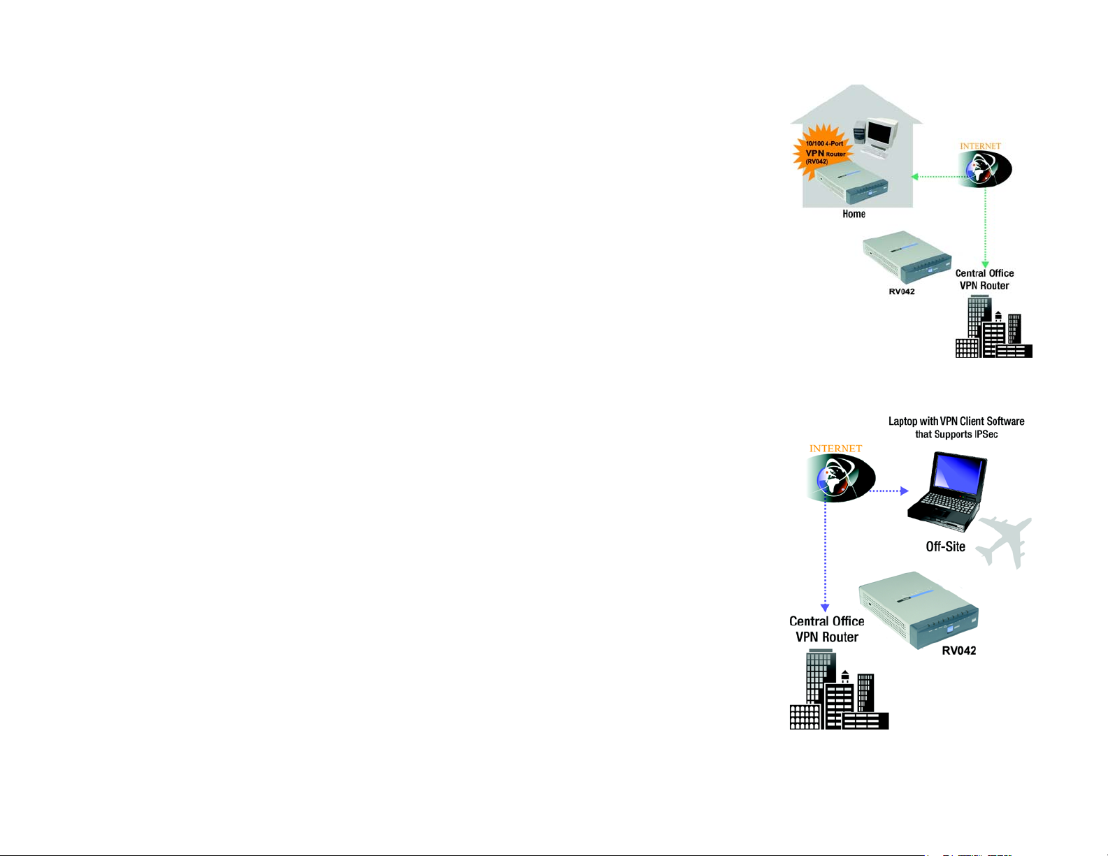
VPN Router to VPN Router
An example of a VPN Router-to-VPN Router VPN would be as follows. (See Figure 2-1.) At home, a telecommuter
uses his VPN Router for his always-on Internet connection. His router is configured with his office's VPN settings.
When he connects to his office's router, the two routers create a VPN tunnel, encrypting and decrypting data. As
VPNs utilize the Internet, distance is not a factor. Using the VPN, the telecommuter now has a secure connection
to the central office's network, as if he were physically connected.
Computer (using VPN client software that supports IPSec) to VPN Router
The following is an example of a computer-to-VPN Router VPN. (See Figure 2-2.) In her hotel room, a traveling
businesswoman dials up her ISP. Her notebook computer has VPN client software that is configured with her
office's VPN settings. She accesses the VPN client software that supports IPSec and connects to the VPN Router
at the central office. As VPNs utilize the Internet, distance is not a factor. Using the VPN, the businesswoman now
has a secure connection to the central office's network, as if she were physically connected.
Figure 2-1: VPN Router-to-VPN Router VPN
For additional information and instructions about creating your own VPN, please visit Linksys’s website at
www.linksys.com.
Chapter 2: Networking Basics
What is a VPN?
Figure 2-2: Computer-to-VPN Router VPN
7
Page 17
10/100 4-Port VPN Router
Chapter 3: Getting to Know the Router
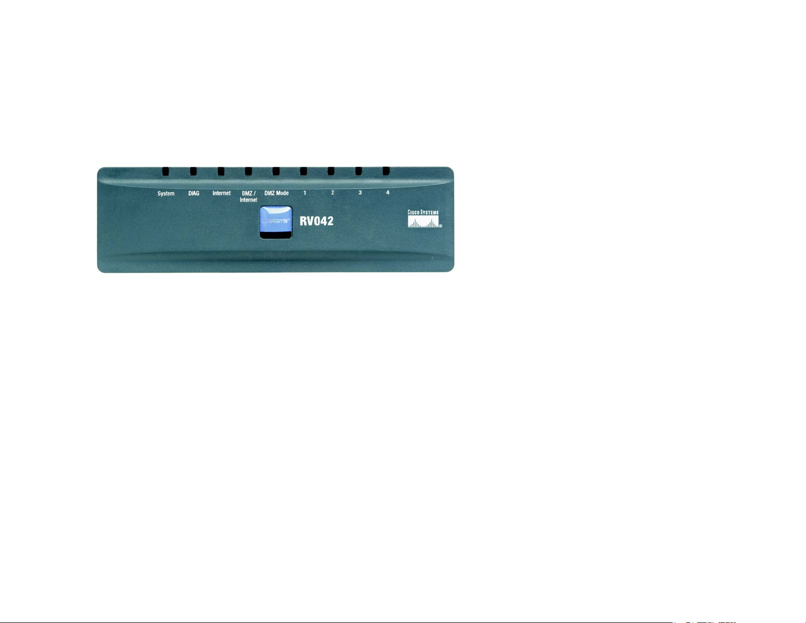
The Front Panel
The Router’s LEDs are located on the front panel of the Router.
Figure 3-1: Front Panel
LEDs
System Green. The System LED lights up when the Router is powered on. If the LED is flashing,
the Router is running a diagnostic test.
Diag Orange. The Diag LED lights up when the system is not ready. The LED goes off when
the system is ready.
Internet Green. The Internet LED lights up when the Router is connected to your cable or DSL
modem.
DMZ/Internet Green. The DMZ/Internet LED lights up when the Router is connected to your cable or
DSL modem when used as an Internet port, and it lights up when the Router is
connected to the hub, switch, or public server when used as a DMZ port.
DMZ Mode Green. The DMZ Mode LED lights up when the Router is using DMZ mode.
1-4 (LAN) Green. The LAN LED serves two purposes. If the LED is continuously lit, the Router is
connected to a device through the corresponding port (1, 2, 3, or 4). If the LED is
flashing, the Router is actively sending or receiving data over that port.
Chapter 3: Getting to Know the Router
The Front Panel
8
Page 18
10/100 4-Port VPN Router
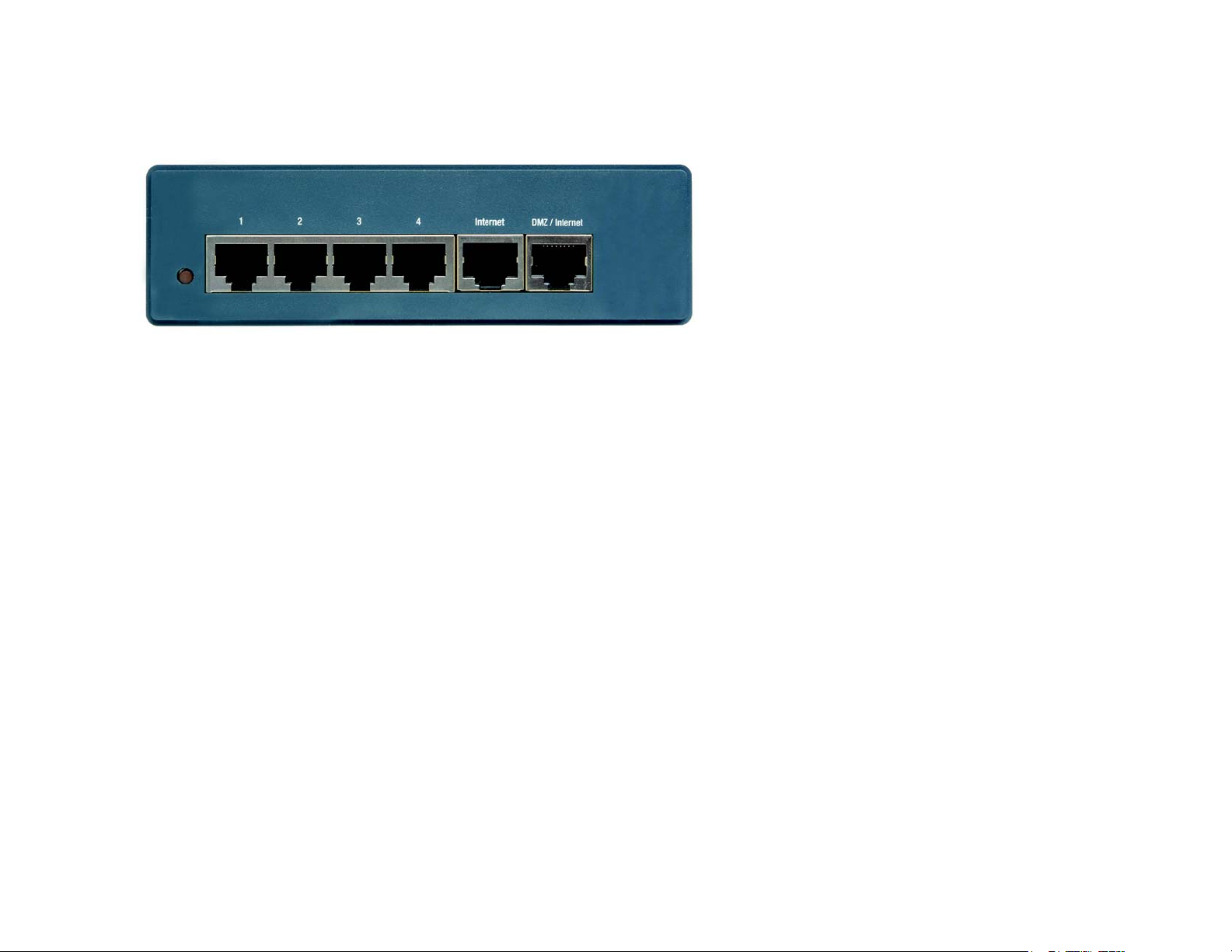
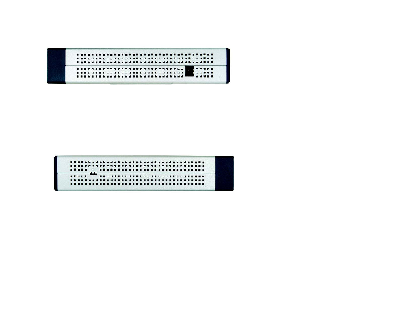
The Back and Side Panels
The Router’s ports and Reset button are located on the back panel of the Router.
LAN
WAN1
WAN2
Figure 3-2: Back Panel
Reset Button
Reset Button The Reset button can be used in one of two ways:
If the Router is having problems connecting to the Internet, press the Reset button for
just a second with a paper clip or a pencil tip. This is similar to pressing the Reset
button on your PC to reboot it.
If you are experiencing extreme problems with the Router and have tried all other
troubleshooting measures, press and hold in the Reset button for 30 seconds. This will
restore the factory defaults and clear all of the Router’s settings, such as port
forwarding or a new password.
Ports
1-4 (LAN) These four LAN (Ethernet) ports connect to network devices, such as PCs, print
servers, or additional switches.
Internet (WAN1) The Internet port connects to a cable or DSL modem.
DMZ/Internet (WAN2) The DMZ/Internet port can be used in two different ways: a second Internet port, or
DMZ port. When used as an additional Internet port, it connects to a cable or DSL
modem. When used as a DMZ port, it connects to a hub, switch, or public server.
Chapter 3: Getting to Know the Router
The Back and Side Panels
9
Page 19
10/100 4-Port VPN Router
The power port is located on the right side panel of the Router.
Figure 3-3: Right Side Panel
Power The Power port is where you will connect the included AC power cable.
‘
The security slot is located on the left side panel.
Figure 3-4: Left Side Panel
Security Slot The security slot is where you can attach a lock so the Router will be protected from
theft.
Proceed to “Chapter 4: Connecting the Router.”
Chapter 3: Getting to Know the Router
The Back and Side Panels
10
Page 20
10/100 4-Port VPN Router
Chapter 4: Connecting the Router
Overview
To set up your network, you will do the following:
• Connect the Router to one of your PCs according to the instructions in this chapter.
• If necessary, configure your PCs to obtain an IP address automatically from the Router, according to “Chapter
5: Configuring the PCs.” (By default, Windows 98, 2000, Millennium, and XP computers are set to obtain an IP
address automatically, so unless you have changed the default setting, then you will not need to configure
your PCs.)
• Set up and configure the Router with the setting(s) provided by your Internet Service Provider (ISP) according
to “Chapter 6: Set up and Configure the Router.”
The installation technician from your ISP should have left the setup information with you after installing your
broadband connection. If not, you can call your ISP to request the information. Once you have the setup
information for your specific type of Internet connection, then you can begin installation and setup of the Router.
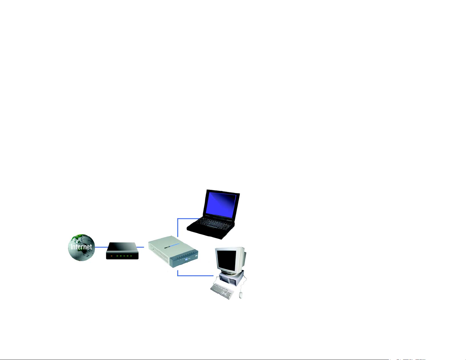
Chapter 4: Connecting the Router
Overview
Notebook with
Ethernet Adapter
Cable or DSL
Modem
10/100 4-Port
VPN Router
PC with Ethernet
Adapter
Figure 4-1: Example of a Typical Network
11
Page 21
10/100 4-Port VPN Router
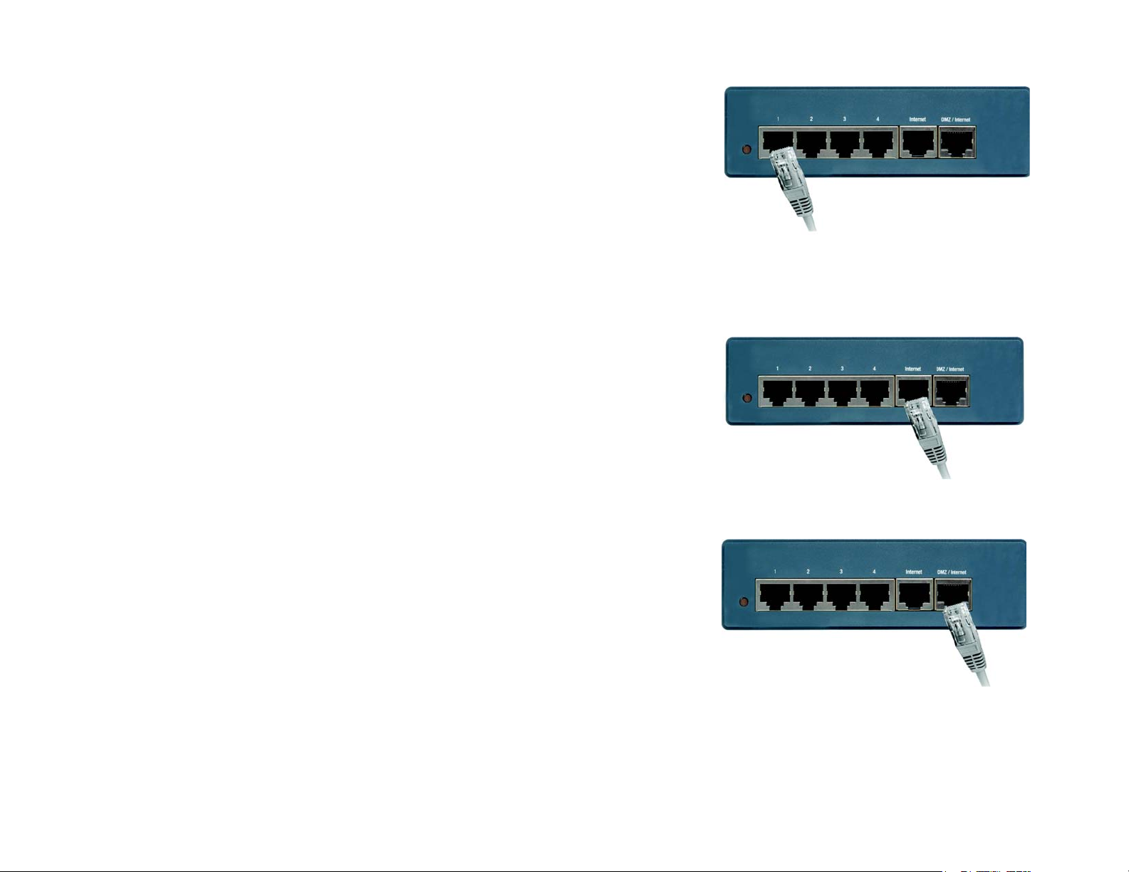
Connection Instructions
1. Before you begin, make sure that all of your hardware is powered off, including the Router, PCs, hubs,
switches, and cable or DSL modem.
2. Connect one end of an Ethernet network cable to one of the numbered ports on the back of the Router (see
Figure 4-2). Connect the other end to an Ethernet port on a network device, e.g., a PC, print server, hub, or
switch.
Repeat this step to connect more PCs or other network devices to the Router.
3. Connect your cable or DSL modem’s Ethernet cable to the Router’s Internet port. If using the DMZ/Internet
port, connect a second cable to it, and the other end to the network device, e.g., modem or public server.
4. Power on the cable or DSL modem and the other network device if using one.
Figure 4-2: Connect a PC
Figure 4-3: Connect the Internet
Chapter 4: Connecting the Router
Connection Instructions
Figure 4-4: Connect the DMZ/Internet
12
Page 22

10/100 4-Port VPN Router
5. Connect the included AC power cable to the Router’s Power port on the side of the Router, as shown in Figure
4-5, and then plug the power adapter into an electrical outlet.
The System LED on the front panel will light up as soon as the power adapter is connected properly.
If you need to configure your PCs, proceed to “Chapter 5: Configuring the PCs.” Otherwise, proceed to
“Chapter 6: Set Up and Configure the Router.”
Figure 4-5: Connect the Power
Chapter 4: Connecting the Router
Connection Instructions
13
Page 23
10/100 4-Port VPN Router
Chapter 5: Configuring the PCs
Overview
The instructions in this chapter will help you configure each of your computers so they will be able to
communicate with the Router. Each PC must be set to obtain an IP address (or TCP/IP) address automatically
(called DHCP). Computers use IP addresses to communicate with each other across a network or the Internet.
Note: These instructions apply only to Windows 98, Millennium, 2000, or XP computers. By default,
Windows 98, 2000, Millennium, and XP have TCP/IP installed and are set to obtain an IP address
automatically. If you have not made any changes to your PC’s default network settings, then proceed
to “Chapter 6: Set Up and Configure the Router.”
Find out which operating system your computer is running, such as Windows 98, Millennium, 2000, or XP. If
you’re not sure, you can find out by clicking the Start button. On the left side of the taskbar, it will say which
operating system your computer is using.
You may need to do this for each computer you are connecting to the Router.
The next few pages tell you, step by step, how to configure your network settings based on the type of Windows
operating system you are using. Make sure that an Ethernet card or adapter has been successfully installed in
each PC you will configure. Once you’ve configured your computers, proceed to “Chapter 6: Set Up and Configure
the Router.”
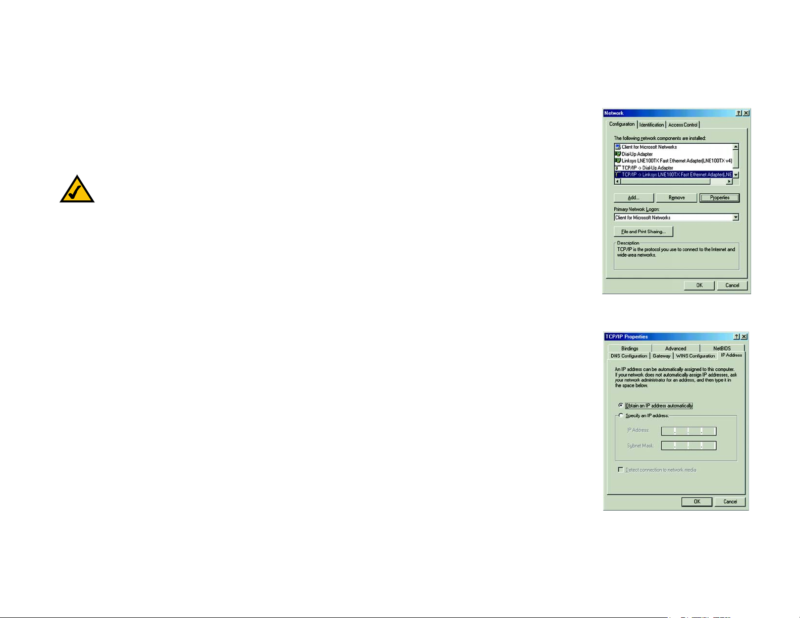
Configuring Windows 98 and Millennium PCs
1. Click the Start button. Click Settings and then Control Panel. From there, double-click the Network icon.
2. On the Configuration tab, select the TCP/IP line for the applicable Ethernet adapter, as shown in Figure 5-1.
Do not choose a TCP/IP entry whose name mentions Dial-Up Adapter, PPPoE, VPN, or AOL. If the word TCP/IP
appears by itself, select that line. (If there is no TCP/IP line listed, refer to Windows Help or your Ethernet
adapter’s documentation to install TCP/IP now.) Click the Properties button.
3. Click the IP Address tab and select Obtain an IP address automatically, as shown in Figure 5-2.
4. Now click the Gateway tab to ensure that the Installed Gateway field is left blank. Click the OK button.
Chapter 5: Configuring the PCs
Overview
Figure 5-1: TCP/IP for Windows 98
and Me
Figure 5-2: Obtain an IP address
automatically for Windows 98
and Me
14
Page 24
10/100 4-Port VPN Router
5. Click the OK button again. Windows may ask you for the original Windows installation disk or additional files.
Supply them by pointing to the correct file location, e.g., D:\win98, D:\win9x, c:\windows\options\cabs, etc. (if
“D” is the letter of your CD-ROM drive).
6. Windows may ask you to restart your PC. Click the Yes button. If Windows does not ask you to restart, restart
your computer anyway.
Go to “Chapter 6: Set Up and Configure the Router.”
Configuring Windows 2000 PCs
1. Click the Start button. Click Settings and then Control Panel. From there, double-click the Network and
Dial-up Connections icon.
2. Select the Local Area Connection icon for the applicable Ethernet adapter (usually it is the first Local Area
Connection listed). Double-click the Local Area Connection. Click the Properties button.
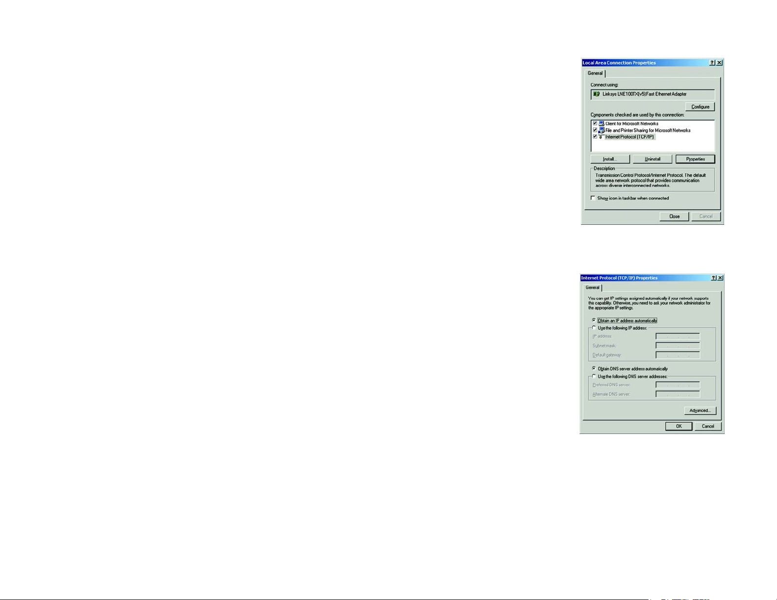
3. Select Internet Protocol (TCP/IP), and click the Properties button. See Figure 5-3.
4. Select Obtain an IP address automatically (see Figure 5-4). Once the new windows appears, click the OK
button. Click the OK button again to complete the PC configuration.
5. Restart your computer.
Go to “Chapter 6: Set Up and Configure the Router.”
Configuring Windows XP PCs
The following instructions assume you are running Windows XP with the default interface. If you are using the
Classic interface (where the icons and menus look like previous Windows versions), follow the instructions for
Windows 2000.
1. Click the Start button. Click Settings and then Control Panel. Click the Network and Internet Connections
icon and then the Network Connections icon.
2. Select the Local Area Connection icon for the applicable Ethernet adapter (usually it is the first Local Area
Connection listed). Double-click the Local Area Connection. Click the Properties button.
Figure 5-3: Internet Protocol
(TCP/IP) for Windows 2000
Figure 5-4: Obtain an IP address
automatically for Windows 2000
Chapter 5: Configuring the PCs
Configuring Windows 2000 PCs
15
Page 25
10/100 4-Port VPN Router
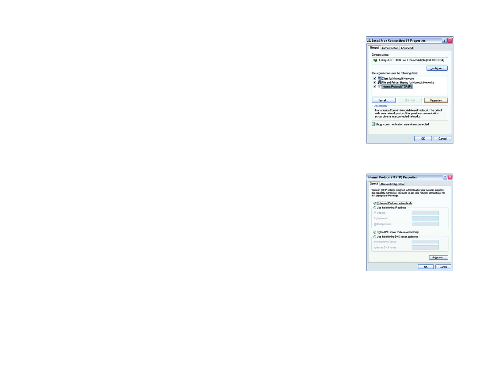
3. Select Internet Protocol (TCP/IP), and click the Properties button. See Figure 5-5.
4. Select Obtain an IP address automatically (see Figure 5-6). Once the new window appears, click the OK
button. Click the OK button again (or the Close button if any settings were changed) to complete the PC
configuration.
5. Restart your computer.
Go to “Chapter 6: Set Up and Configure the Router.”
Figure 5-5: Internet Protocol
(TCP/IP) for Windows XP
Chapter 5: Configuring the PCs
Configuring Windows XP PCs
Figure 5-6: Obtain an IP address
automatically for Windows XP
16
Page 26

10/100 4-Port VPN Router
Chapter 6: Set Up and Configure the Router
Overview
For your convenience, use the Router’s Web-based Utility to set it up and configure it. This chapter will explain all
of the functions in this Utility.
There are eleven main tabs in the Utility: System Summary, Setup, DHCP, System Management, Firewall, VPN,
Log, Wizard, Support, and Logout. Additional tabs will be available after you click one of the main tabs. The tabs
are described below:
System Summary Tab
The System Summary Tab displays the router’s current status and settings. This information is read only. If you
click the button with underline, it will hyperlink to related setup pages.
Setup Tab
• Network. Enter the Internet connection and network settings on this screen.
• Password. You can change the Router’s password on this screen. it is strongly recommended that you change
the Router's password from the default.
• Time. Change the time on this screen.
• DMZ Host. The DMZ (Demilitarized Zone) Host feature allows one local user to be exposed to the Internet to
use a special-purpose service such as Internet gaming or video conferencing.
• Forwarding. Port forwarding can be used to set up public services on your network. You may use this function
to establish a Web server or FTP server via an IP Gateway.
• UPnP. UPnP forwarding can be used to set up public services on your network.
• One-to-One NAT. One-to-One NAT creates a relationship which maps valid external addresses to internal
addresses hidden by NAT.
• MAC Clone. Some ISPs require that you register a MAC address. This feature “clones” your network adapter's
MAC address onto the Router, and prevents you from having to call your ISP to change the registered MAC
address to the Router's MAC address.
Chapter 6: Set Up and Configure the Router
Overview
17
Page 27

10/100 4-Port VPN Router
• DDNS. DDNS (Dynamic DNS) service allows you to assign a fixed domain name to a dynamic WAN IP address.
This allows you to host your own Web, FTP or other type of TCP/IP server in your LAN.
• Advanced Routing. The Router's dynamic routing feature can be used to automatically adjust to physical
changes in the network's layout.
DHCP Tab
• Setup. You can enable/disable the DHCP server, set up client lease time, DHCP IP Range, and the WINS Server
IP address.
• Status. A Status page is available to review DHCP Server Status.
System Management Tab
• Dual WAN. There are two functions provided for users – Smart Link Backup and Load Balance.
• SNMP. SNMP, or Simple Network Management Protocol, is a network protocol that provides network
administrators with the ability to monitor the status of the Router and receive notification of any critical
events as they occur on the network.
• Diagnostic. The Router has two built-in tools that will help with troubleshooting network problems.
• Factory Default. The “Factory Default” button can be used to clear all of your configuration information and
restore the Router to its factory default settings. Only use this feature if you wish to discard all other
configuration preferences.
• Firmware Upgrade. Users can use the following function to upgrade the Router’s firmware to the newest
version.
• Restart. The recommended method of restarting your Router is to use this “Restart” tool. Restarting with this
button will send out your log file before the box is reset.
• Setting Backup. This tab allows you to make a backup file of your Preferences file for the Router.
Chapter 6: Set Up and Configure the Router
Overview
18
Page 28

10/100 4-Port VPN Router
Firewall Tab
• General. From the Firewall Tab, you can configure the Router to deny or allow specific internal users from
accessing the Internet.
• Access Rules. Network Access Rules evaluate the network traffic's Source IP address, Destination IP address,
and IP protocol type to decide if the IP traffic is allowed to pass through the firewall.
• Content Filter. This tab allows you to filter web access by site and time.
VPN Tab
• Summary. The VPN Summary displays the Summary, Tunnel Status and GroupVPN Status.
• Gateway to Gateway. By setting this page, users can add a new tunnel between two VPN devices.
• Client to Gateway. By setting this page, you can create a new tunnel between a Local VPN device and a
mobile user.
• VPN Pass Through. This tab allows you to disable IPSec Pass Through, PPTP Pass Through, and L2TP Pass
Through.
Log Tab
• System Log. The System Log displays Syslog, E-mail and Log Settings.
• System Statistics. This tab displays the system statistics.
Wizard Tab
• Wizard. Use this tab to access two Setup Wizards, the Basic Setup Wizard and Access Rule Setup Wizard.
Support Tab
• Support. This tab supplies buttons to access the user guide and the Linksys website.
Logout Tab
• Logout. Clicking this tab exits you from the Utility.
Chapter 6: Set Up and Configure the Router
Overview
19
Page 29
10/100 4-Port VPN Router
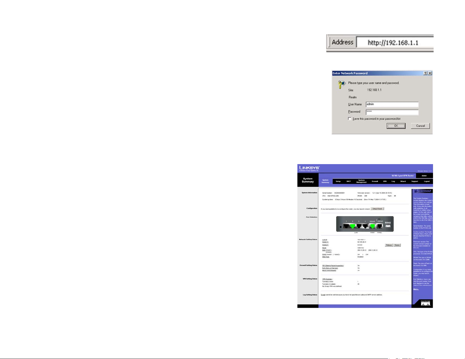
How to Access the Web-based Utility
To access the Web-based Utility of the Router, launch Internet Explorer or Netscape Navigator, and enter the
Router’s default IP address, 192.168.1.1, in the Address field, as shown in Figure 6-1. Press the Enter key.
• A screen will appear asking you for your User name and Password, as shown in Figure 6-2. Enter admin in
the User name field, and enter admin in the Password field. Then click the OK button.
System Summary Tab
The first screen that appears is System Summary Tab. See Figure 6-3. This screen displays the router’s current
status and settings. This information is read only. If you click the button with underline, it will hyperlink to related
setup pages. On the right side of the screen and all other screens in the Utility will be a link to the Site Map, which
has links to all of the Utility’s tabs. Click the Site Map button to view the Site Map. See Figure 6-4. Then, click on
desired tab subject.
System Information
Serial Number: The serial number of the Router.
Firmware version: The current version number of the firmware installed on this unit.
CPU: The type of processor installed on the Router. It is Intel IXP425.
DRAM: The size of DRAM on the board.
Flash: The size of Flash on the board.
Figure 6-1: Router’s IP Address
Figure 6-2: Password
System Up Time: The length of time in Days, Hours, and Minutes that the Router is active and the current time are
displayed.
Configuration
If you need help to re-configure the router, click the Setup Wizard button. To view the figures for the wizard, see
the Wizard Tab section.
Chapter 6: Set Up and Configure the Router
How to Access the Web-based Utility
Figure 6-3: System Summary
20
Page 30

10/100 4-Port VPN Router
Port Statistics
Users can click the port number from the port diagram to see the status of the selected port. If the port is
disabled, it will be red; if enabled, it will be black; if connected, it will be green. In the summary table, it will show
the setting of the port selected by users, such as Type, Link Status (up or down), Port Disable (on or off), Priority
(High or Normal), Speed Status (10Mbps or 100Mbps), Duplex Status (half or full), Auto negotiation (enable or
disable). In the statistics table, it will show the port receive/transmit packet count/packet byte count and Port
Packet Error Count of the selected port. The LAN ports can be configured from the LAN Setup page of the LAN
Management Tab.
Network Setting Status
LAN IP: It shows the current LAN IP Address of the Router, as seen by internal users on the network, and
hyperlinks to the LAN Setting section on the Network page of the Setup Tab.
WAN1 IP: It shows the current WAN1 IP Address of the Router, as seen by external users on the Internet and
hyperlinks to WAN Connection type section on the Network page of the Setup Tab. When users select Obtain an IP
automatically, it shows two buttons, Release and Renew. Users can click the Release button to release the IP that
users already have and click the Renew button to update the DHCP Lease Time or get a new IP. When users select
PPPoE or PPTP, it shows Connect / Disconnect.
WAN2/DMZ IP: It shows the current WAN2 IP Address of the Router, or DMZ IP when DMZ is selected, as seen by
external users on the Internet and hyperlinks to WAN Connection type on the Network page of the Setup Tab.
Mode: It shows the Working Mode (Gateway or Router) and hyperlinks to Dynamic Routing section on the
Advanced Routing page of the Setup Tab.
DNS: It shows all DNS Server Addresses and hyperlinks to WAN Connection Type on the Network page of the
Setup Tab.
DDNS: It shows the status (On/Off) and hyperlinks to DDNS page of the Setup Tab.
DMZ Host: It shows DMZ Private Address and hyperlinks to DMZ Host page of the Setup Tab. The default is
disabled.
Firewall Setting Status
SPI (Stateful Packet Inspection): It shows the status (On/Off) and hyperlinks to the General page of the Firewall
Tab.
DoS (Denial of Service): It shows the status (On/Off) and hyperlinks to the General page of the Firewall Tab.
Figure 6-4: Site Map
Chapter 6: Set Up and Configure the Router
System Summary Tab
21
Page 31

10/100 4-Port VPN Router
Block WAN Request: It shows the status (On/ Off) and hyperlinks to the Block WAN Request section on the General
page of the Firewall Tab.
VPN Setting Status
VPN Summary: It hyperlinks to Summary page of VPN Tab.
Tunnel(s) Used: It shows the number of Tunnels used.
Tunnel(s) Available: It shows the number of Tunnels available.
Current Connected (The Group Name of GroupVPN1) users: It shows the number of users.
Current Connected (The Group Name of GroupVPN2) users: It shows the number of users.
(If GroupVPN is disabled, it will show “No Group VPN was defined.”)
Log Setting Status:
It hyperlinks to the System Log page of Log Tab.
If you have not set up the mail server in Log Tab, it shows “E-mail cannot be sent because you have not specified
an outbound SMTP server address.”
If you have set up the mail server but the log has not come out due to Log Queue Length and Log Time Threshold
settings, it shows “E-mail settings have been configured.”
If you have set up the mail server and the log has been sent to the mail server, it shows “E-mail settings have
been configured and sent out normally.”
If you have set up the mail server and the log cannot be sent to mail server successfully, it shows “E-mail cannot
be sent out, probably use incorrect settings.”
Chapter 6: Set Up and Configure the Router
System Summary Tab
22
Page 32

10/100 4-Port VPN Router
Setup Tab - Network
The Setup screen contains all of the router’s basic setup functions. See Figure 6-5. The device can be used in
most network settings without changing any of the default values. Some users may need to enter additional
information in order to connect to the Internet through an ISP (Internet Service Provider) or broadband (DSL, cable
modem) carrier.
Network
Host Name & Domain Name: Enter a host and domain name for the Router. Some ISPs may require these names
as identification, and these settings can be obtained from your ISP. In most cases, leaving these fields blank will
work.
LAN Setting
This is the Router’s LAN IP Address and Subnet Mask. The default value is 192.168.1.1 for IP address and
255.255.255.0 for the Subnet Mask.
Dual-WAN / DMZ Setting
Before choosing the WAN Connection Type, please choose the Dual-WAN / DMZ Setting first.
DMZ
In order to allow such services, the Router comes with a special DMZ port which is used for setting up public
servers. The DMZ port sits between the local network ports and the Internet port. Servers on the DMZ are publicly
accessible, but they are protected from attacks such as SYN Flooding and Ping of Death. Use of the DMZ port is
optional; it may be left unconnected.
Using the DMZ is preferred and, if practical, a strongly recommended alternative to Public LAN Servers or putting
these servers on the WAN port where they are not protected and not accessible by users on the LAN.
Each of the servers on the DMZ will need a unique, public Internet IP address. The ISP used to connect the
network to the Internet should be able to provide these addresses, as well as information on setting up public
Internet servers. If you plan to use the DMZ Mode, contact your ISP for the Static IP information.
Specify DMZ IP Address: Enter the DMZ IP Address and Subnet Mask.
Click the Save Settings button to save the network settings or click the Cancel Changes button to undo your
changes.
Chapter 6: Set Up and Configure the Router
Setup Tab - Network
Figure 6-5: Setup Tab
23
Page 33

10/100 4-Port VPN Router
WAN Connection Type
Obtain an IP Automatically
If your ISP automatically assigns an IP Address, select Obtain an IP automatically. Your ISP will assign these
values. If you check the box for Use the Following DNS Server Addresses, enter a specific DNS Server IP.
Multiple DNS IP Settings are common. In most cases, the first available DNS entry is used. See Figure 6-6.
Static IP
If you have to specify the WAN IP Address, Subnet Mask, Default Gateway Address, and DNS Server, select Static
IP. You must obtain this information from your ISP. See Figure 6-7.
PPPoE (Point-to-Point Protocol over Ethernet) (most DSL users) See Figure 6-8.
You have to check with your ISP to make sure whether PPPoE should be enabled or not. If they do use PPPoE:
Figure 6-6: Obtain an IP Automatically
1. Enter your User Name and Password.
2. If you select Connect on Demand option, the PPPoE connection will be disconnected if it has been idle for a
period longer than the Max Idle Time setting.
3. If you select Keep Alive option, the Router will keep the connection alive by sending out a few data packets
at the Redial Period, so your Internet service thinks that the connection is still active.
PPTP (Point-to-Point Tunneling Protocol) See Figure 6-9.
1. Enter the Specify WAN IP Address, Subnet Mask and Default Gateway Address that is provided by your ISP.
2. Enter your User Name and Password.
3. If you select Connect on Demand option, the connection will be disconnected if it has been idle for a period
longer than the Max Idle Time setting.
4. If you select Keep Alive option, the Router will keep the connection alive by sending out a few data packets
at the Redial Period, so your Internet service thinks that the connection is still active.
Chapter 6: Set Up and Configure the Router
Setup Tab - Network
Figure 6-7: Static IP
Figure 6-8: PPPoE
Figure 6-9: PPTP
24
Page 34

10/100 4-Port VPN Router
Setup Tab - Password
The Router's default User Name and password is admin, and it is strongly recommended that you change the
Router's password from the default. If you leave the password field blank, all users on your network will be able
to access the Router simply by entering admin into the password field. See Figure 6-10.
Old Password: Enter the old password. The default Password is ‘admin’ when you first power up the Router.
(Note: The password cannot be recovered if it is lost or forgotten. If the password is lost or forgotten, you have to
reset the Router to its factory default settings.)
New Password: Enter a new password for the Router. Your password must be less than 15 characters long and it
can’t contain any spaces.
Confirm New Password: Re-enter the password for confirmation.
Click the Save Settings button to save the Password settings or click the Cancel Changes button to undo the
changes.
Setup Tab - Time
Time
The Router uses the time settings to time stamp log events, to automatically update the Content Filter List, and
for other internal purposes. See Figure 6-11.
Set the local time using Network Time Protocol (NTP) automatically or manually.
Automatic: Select the Time Zone and enter the Daylight Saving and NTP Server. The default Time Zone is Pacific
Time.
Manual: Enter the Hours, Minutes, Seconds, Month, Day and Year.
Click the Save Settings button to save the Time settings or click the Cancel Changes button to undo the
changes.
Figure 6-10: Password
Figure 6-11: Time
Chapter 6: Set Up and Configure the Router
Setup Tab - Password
25
Page 35

10/100 4-Port VPN Router
Setup Tab - DMZ Host
The DMZ (Demilitarized Zone) Host feature allows one local user to be exposed to the Internet to use a
special-purpose service such as Internet gaming or video conferencing. See Figure 6-12.
Enter the DMZ Private IP Address to access the DMZ Host settings. The Default value zero (0) will deactivate the
DMZ Host.
Click the Save Settings button to save the DMZ Host setting or click the Cancel Changes button to undo the
changes.
Setup Tab - Forwarding
Port forwarding can be used to set up public services on your network. When users from the Internet make
certain requests on your network, the Router can forward those requests to computers equipped to handle the
requests. If, for example, you set the port number 80 (HTTP) to be forwarded to IP Address 192.168.1.2, then all
HTTP requests from outside users will be forwarded to 192.168.1.2. See Figure 6-13.
You may use this function to establish a Web server or FTP server via an IP Gateway. Be sure that you enter a valid
IP Address. (You may need to establish a static IP address in order to properly run an Internet server.) For added
security, Internet users will be able to communicate with the server, but they will not actually be connected. The
packets will simply be forwarded through the Router.
Figure 6-12: DMZ Host
Port Range Forwarding
1. Select the Service from the pull-down menu. See Figure 6-14.
2. If the Service you need is not listed in the menu, please click the Service Management button to add the
new Service Name, and enter the Protocol and Port Range. Click the Add to List button. Then, click the Save
Setting button. Click the Exit button.
3. Enter the IP Address of the server that you want the Internet users to access. Then enable the entry.
4. Click the Add to List button, and configure as many entries as you would like. You also can Delete selected
application.
Chapter 6: Set Up and Configure the Router
Setup Tab - DMZ Host
Figure 6-13: Forwarding
Figure 6-14: Service Management
26
Page 36

10/100 4-Port VPN Router
Port Triggering
Some Internet applications or games use alternate ports to communicate between server and LAN host. When
you want to use those applications, enter the triggering (outgoing) port and alternate incoming port in this table.
The Router will forward the incoming packets to the LAN host.
1. Enter the application name, range of port numbers, and the incoming port range.
2. You can click the Add to List button to add Port Triggering or Delete selected application.
Click the Save Settings button to save the settings, click the Cancel Changes button to undo your changes, click
the Show Tables to see the details.
Setup Tab - UPnP Page
UPnP forwarding can be used to set up public services on your network. Windows XP can modify those entries via
UPnP when UPnP function is enabled by selecting Yes. See Figure 6-15.
1. Select the Service from the pull-down menu.
2. If the Service you need is not listed in menu, please click the Service Management button to add the new
Service Name, and enter the Protocol and Port Range. Click the Add to List button. Then, click the Save
Setting button. Click the Exit button.
3. Enter the Name or IP Address of the server that you want the Internet users to access. Then enable the entry.
Figure 6-15: UPnP
Click the Add to List button, and configure as many entries as you would like. You also can Delete selected
application.
Setup Tab - One-to-One NAT
One-to-One NAT creates a relationship which maps valid external addresses to internal addresses hidden by NAT.
Machines with an internal address may be accessed at the corresponding external valid IP address. See Figure
6-16.
Creating this relationship between internal and external addresses is done by defining internal and external
address ranges of equal length. Once that relationship is defined, the machine with the first internal address is
accessible at the first IP address in the external address range, and the second machine at the second external IP
address, and so on.
Chapter 6: Set Up and Configure the Router
Setup Tab - UPnP Page
Figure 6-16: One-to-One NAT
27
Page 37

10/100 4-Port VPN Router
Consider a LAN for which the ISP has assigned the IP addresses range from 209.19.28.16 to 209.19.28.31, with
209.19.28.16 used as the Router’s WAN IP (NAT Public) Address. The address range of 192.168.168.1 to
192.168.168.255 is used for the machines on the LAN. Typically, only machines that have been designated as
Public LAN Servers will be accessible from the Internet. However, with One-to-One NAT, the machines with the
internal IP addresses of 192.168.168.2 to 192.168.168.15 may be accessed at the corresponding external IP
address.
Note: The Router’s WAN IP (NAT Public) Address may not be included in a range.
One-to-One NAT: Enable: If you check the box, you will enable One-to-One NAT.
Private Range Begin: Enter the beginning IP address of the private address range being mapped in the Private
Range Begin field. This will be the IP address of the first machine being made accessible from the Internet.
Public Range Begin: Enter the beginning IP address of the public address range being mapped in the Public
Range Begin field. This address will be assigned by the ISP. The Router’s WAN IP (NAT Public) Address cannot be
included in the range.
Range Length: Enter the number of IP addresses for the range. The range length may not exceed the number of
valid IP address. Up to 64 ranges may be added. To map a single address, use a Range Length of 1.
Note: One-to-One NAT will change the way the firewall functions work. Access to machines on the LAN from the
Internet will be allowed unless Network Access Rules are set. You can click Add to List button or Delete
selected range.
Click the Save Settings button to save the settings or click the Cancel Changes button to undo your changes.
Setup Tab - MAC Clone
Some ISPs require that you register a MAC address. This feature “clones” your network adapter's MAC address
onto the Router, and prevents you from having to call your ISP to change the registered MAC address to the
Router's MAC address. The Router's MAC address is a 12-digit code assigned to a unique piece of hardware for
identification. See Figure 6-17.
Input the MAC Address in the User Defined WAN1 or WAN2 MAC Address field or select MAC Address from this
PC.
Click Save Settings to save the MAC Cloning settings or click the Cancel Changes button to undo your changes.
Chapter 6: Set Up and Configure the Router
Setup Tab - MAC Clone
Figure 6-17: MAC Clone
28
Page 38

10/100 4-Port VPN Router
Setup Tab - DDNS
DDNS (Dynamic DNS) service allows you to assign a fixed domain name to a dynamic WAN IP address. This
allows you to host your own Web, FTP or other type of TCP/IP server in your LAN. See Figure 6-18.
Before configuring DDNS, you need to visit www.dyndns.org and register a domain name. (The DDNS service is
provided by DynDNS.org).
DDNS Service: The DDNS feature is disabled by default. To enable this feature, just select DynDNS.org from the
pull-down menu, and enter the User name, Password, and Host Name of the account you set up with DynDNS.org.
Your IP Address: The Router’s current Internet IP Address is displayed here. Because it is dynamic, this will
change.
Status: The status of the DDNS function and Internet status is displayed.
Click the Save Settings button to save the DDNS settings or click the Cancel Changes button to undo your
changes.
Setup Tab - Advanced Routing
Dynamic Routing
The Router's dynamic routing feature can be used to automatically adjust to physical changes in the network's
layout. The Router uses the dynamic RIP protocol. It determines the route that the network packets take based on
the fewest number of hops between the source and the destination. The RIP protocol regularly broadcasts routing
information to other routers on the network. See Figure 6-19.
Working Mode: Select Gateway mode if your Router is hosting your network’s connection to the Internet. Select
Router mode if the Router exists on a network with other routers, including a separate network gateway that
handles the Internet connection. In Router Mode, any computer connected to the Router will not be able to
connect to the Internet unless you have another router function as the gateway.
RIP (Routing Information Protocol): The Router, using the RIP protocol, calculates the most efficient route for the
network’s data packets to travel between the source and the destination, based upon the shortest paths.
Receive RIP versions: Choose the RX protocol you want for receiving data from the network. (None, RIPv1, RIPv2,
Both RIPv1 and v2).
Figure 6-18: DDNS
Transmit RIP versions: Choose the TX protocol you want for transmitting data on the network. (None, RIPv1,
RIPv2-Broadcast, RIPv2-Multicast)
Chapter 6: Set Up and Configure the Router
Setup Tab - DDNS
Figure 6-19: Advanced Routing
29
Page 39

10/100 4-Port VPN Router
Static Routing
You will need to configure Static Routing if there are multiple routers installed on your network. The static routing
function determines the path that data follows over your network before and after it passes through the Router.
You can use static routing to allow different IP domain users to access the Internet through this device. This is an
advanced feature. Please proceed with caution.
This Router is also capable of dynamic routing (see the Dynamic Routing tab). In many cases, it is better to use
dynamic routing because the function will allow the Router to automatically adjust to physical changes in the
network's layout. In order to use static routing, the Router's DHCP settings must be disabled.
To set up static routing, you should add routing entries in the Router's table that tell the device where to send all
incoming packets. All of your network routers should direct the default route entry to the Linksys Router.
Enter the following data to create a static route entry:
1. Destination IP: Enter the network address of the remote LAN segment. For a standard Class C IP domain, the
network address is the first three fields of the Destination LAN IP, while the last field should be zero.
2. Subnet Mask: Enter the Subnet Mask used on the destination LAN IP domain. For Class C IP domains, the
Subnet Mask is 255.255.255.0.
3. Default Gateway: If this Router is used to connect your network to the Internet, then your gateway IP is the
Router's IP Address. If you have another router handling your network's Internet connection, enter the IP
Address of that router instead.
4. Hop Count (max. 15): This value gives the number of nodes that a data packet passes through before reaching
its destination. A node is any device on the network, such as switches, PCs, etc.
5. Interface: (LAN, WAN1, WAN2/DMZ) Interface tells you whether your network is on the LAN or the WAN, or the
Internet. If you’re connecting to a sub-network, select LAN. If you’re connecting to another network through
the Internet, select WAN.
Click Add to list to add a route entry or click Delete Selected IP to delete the static route entry.
Click the Save Settings button to save the Routing settings, click the Cancel Changes button to undo your
changes or click the Show Routing Table button to view the current routing table.
Chapter 6: Set Up and Configure the Router
Setup Tab - Advanced Routing
30
Page 40

10/100 4-Port VPN Router
DHCP Tab - Setup
Setup
The Router can be used as a DHCP (Dynamic Host Configuration Protocol) server on your network. A DHCP server
assigns available IP addresses to each computer on your network automatically. If you choose to enable the DHCP
server option, you must configure all of the PCs on your LAN to connect to a DHCP server. See Figure 6-20.
If the Router's DHCP server function is disabled, you have to carefully configure the IP address, Mask, and DNS
settings of every computer on your network. Be careful not to assign the same IP Address to different computers.
Make any changes to the available fields as described below.
Enable DHCP Server: Check the box to enable the DHCP Server. If you already have a DHCP server on your
network, leave the box blank.
Dynamic IP
Client Lease Time: This is the lease time assigned if the computer (DHCP client) requests one. The range is 5 ~
43,200 Minutes.
Range Start/End: Enter a starting IP address and ending IP address to make a range to assign dynamic IPs. The
default range is 100~149.
WINS
Windows Internet Naming Service (WINS) is a service that resolves NetBIOS names to IP addresses. The WINS is
assigned if the computer (DHCP client) requests one. If you do not know the WINS, leave it as 0.
Click the Save Settings button to save the DHCP settings or click the Cancel Changes button to undo the
changes.
DHCP Tab - Status
A Status page is available to review DHCP Server Status. The DHCP Server Status reports the IP of the DHCP
Server, the number of Dynamic IP Used, DHCP Available and Total. Client Table shows the current DHCP Client
information. You will see the related information (Client Host Name, IP Address, MAC Address, and Leased Time)
of all network clients using the DHCP server. Click the Trash Can icon to delete the line, and the IP Address of the
Client Host got will be released, or click the Refresh button to refresh the Client Table. See Figure 6-21.
Figure 6-20: DHCP Setup
Figure 6-21: DHCP Status
Chapter 6: Set Up and Configure the Router
DHCP Tab - Setup
31
Page 41

10/100 4-Port VPN Router
System Management Tab - Dual-WAN
Dual-WAN
There are two functions provided for users – Smart Link Backup and Load Balance. If you selected DMZ on the
setup page, you cannot do the Dual-WAN settings here.
If Smart Link Backup is selected, you only need to choose which WAN port is the primary and then the other will
be the backup. See Figure 6-22.
If Load Balance is selected, there will be two main choices: By Traffic – Intelligent Balancer (Auto) and user
defined. See Figure 6-23.
First, choose the Max. Bandwidth of Upstream (64K/128K/256K/384K/512K/1024K/1.5M/2M/2.5M or above) and
Downstream (512K/1024K/1.5M/2M/2.5M or above) for WAN1 and WAN2, as provided by your ISP.
Intelligent Balancer (Auto): When choosing Intelligent Balancer, it will automatically compute the maximum
bandwidth of WAN1 and WAN2 by using Weighted Round Robin to balance the loading.
If (upstream / downstream / upstream or downstream) bandwidth is excessive (30%, 40%, 50%, 60%, 70%, 80%,
90%), bring up the second link.
When there is an inactivity time-out (None/10min/20min/30min/40min/50min/60min), the second link will be
terminated.
Figure 6-22: Dual-WAN Smart Link Backup
Click the Save Settings button to save the Dual WAN Load Balance settings or click the Cancel Changes button
to undo the changes.
System Management Tab - SNMP
SNMP, or Simple Network Management Protocol, is a network protocol that provides network administrators with
the ability to monitor the status of the Router and receive notification of any critical events as they occur on the
network. The Router supports SNMP v1/v2c and all relevant Management Information Base II (MIBII) groups. The
appliance replies to SNMP Get commands for MIBII via any interface and supports a custom MIB for generating
trap messages. See Figure 6-24.
To configure SNMP, enter the necessary information in the following fields:
Enable SNMP: SNMP is enabled by default. To disable the SNMP agent, leave the box blank.
System Name: This is the hostname of the Router.
Chapter 6: Set Up and Configure the Router
System Management Tab - Dual-WAN
Figure 6-23: Dual WAN Load Balance
Figure 6-24: SNMP
32
Page 42

10/100 4-Port VPN Router
System Contact: Enter the name of the network administrator for the Router.
System Location: The network administrator's contact information is placed into this field. Enter an E-mail
address, telephone number, or pager number.
Get Community Name: Create a name for a group or community of administrators who can view SNMP data. The
default value is “Public”.
Set Community Name: Create a name for a group or community of administrators who can receive SNMP traps. A
name must be entered.
Trap Community Name: Type the Trap Community Name, which is the password sent with each trap to the SNMP
manager.
Send SNMP Trap to: Enter the IP or Domain Name in this field and the Router will send traps to it.
Click the Save Settings button to save the SNMP settings or click the Cancel Changes button to undo your
changes.
System Management Tab - Diagnostic
The Router has two built-in tools that will help with troubleshooting network problems.
DNS Name Lookup
The Internet has a service called the Domain Name Service (DNS), which allows users to enter an easily
remembered host name, such as www.RV042.com, instead of numerical TCP/IP addresses to access Internet
resources. The Router has a DNS lookup tool that will return the numerical TCP/IP address of a host name.
Enter the host name to look up in the Look up the name field and click the Go button. Do not add the prefix
http://, otherwise the result will be Address Resolving Failed. The Router will then query the DNS server and
display the result at the bottom of the screen. See Figure 6-25.
Note: The IP address of the DNS server must be entered in the Network Settings page for the DNS Name Lookup
feature to function.
Ping
The Ping test bounces a packet off a machine on the Internet back to the sender. This test shows if the Router is
able to contact the remote host. If users on the LAN are having problems accessing services on the Internet, try
Chapter 6: Set Up and Configure the Router
System Management Tab - Diagnostic
Figure 6-25: DNS Name Lookup
Figure 6-26: Ping
33
Page 43

10/100 4-Port VPN Router
pinging the DNS server, or other machine at the ISP’s location. If this test is successful, try pinging devices
outside the ISP. This will show if the problem lies with the ISP’s connection. See Figure 6-26.
Enter the IP address of the device being pinged and click the Go button. The test will take a few seconds to
complete. Once completed, a message showing the results will be displayed at the bottom of the Web browser
window. The results include Packets transmitted / received / loss and Round Trip Time (Minimum, Maximum, and
Average).
Note: Ping requires an IP address. The Router’s DNS Name Lookup tool may be used to find the IP address of a
host.
System Management Tab - Factory Default
The “Factory Default” button can be used to clear all of your configuration information and restore the Router to
its factory default settings. Only use this feature if you wish to discard all other configuration preferences.
Click the Return to Factory Default Setting button if you want to restore the Router to the factory default
settings. See Figure 6-27. After clicking the button, another screen, as shown in Figure 28 will appear. Click OK to
continue. Another screen will appear while the system reboots, as shown in Figure 29.
Figure 6-27: Factory Default
Figure 6-28: Are You Sure
Chapter 6: Set Up and Configure the Router
System Management Tab - Factory Default
Figure 6-29: System is Rebooting
34
Page 44

10/100 4-Port VPN Router
System Management Tab - Firmware Upgrade
Firmware Upgrade
Users can use the following function to upgrade the Router’s firmware to the newest version. If you have already
downloaded the firmware into your computer, then click the Browse button to look for the file. Then, click the
Firmware Upgrade Right Now button. See Figure 6-30.
Firmware Download
Users can click the Firmware Download from Linksys Web Site button to link to the downloads on the Support
page of the Linksys website. Select the Router from the pull-down menu and choose the firmware from the
options. After downloading the firmware, follow the Firmware Upgrade instructions above.
System Management Tab - Restart
The recommended method of restarting your Router is to use this “Restart” tool. Restarting with this button will
send out your log file before the box is reset. Click the Restart Router button to restart the Router. See Figure
6-31.
System Management Tab - Setting Backup
This tab allows you to make a backup file of your Preferences file for the Router. See Figure 6-32.
Import Configuration File:
You will need to specify where your Preferences file is located. Click the Browse button, and your browser will
bring up a dialog that will allow you to select a file that you have previously saved using the Export button. After
you select the file, click the Import button. This process may take up to a minute. You will then need to restart
your Router in order for the changes to take effect.
Figure 6-30: Firmware Upgrade
Figure 6-31: Restart
Chapter 6: Set Up and Configure the Router
System Management Tab - Firmware Upgrade
Figure 6-32: Setting Backup
35
Page 45

10/100 4-Port VPN Router
Export Configuration File:
To use this feature, click the Export button, and your browser will bring up a dialog asking you where you would
like to store your Preferences file. This file will be called “RV042.exp” by default, but you may rename it if you
wish. This process may take up to a minute. See Figure 33.
Firewall Tab - General
From the Firewall Tab, you can configure the Router to deny or allow specific internal users from accessing the
Internet. You can also configure the Router to deny or allow specific Internet users from accessing the internal
servers. You can set up different packet filters for different users that are located on internal (LAN) side or
external (WAN) side based on their IP addresses or their network Port number. See Figure 6-36.
Firewall: The default is enabled. If users disable the Firewall function, SPI, DoS, Block WAN Request will be
disabled, Remote Management will be enabled and Access Rules and Content Filter will be disabled.
SPI (Stateful Packet Inspection): The Router's Firewall uses Stateful Packet Inspection to maintain connection
information that passes through the firewall. It will inspect all packets based on the established connection, prior
to passing the packets for processing through a higher protocol layer.
DoS (Denial of Service): Protect internal networks from Internet attacks, such as SYN Flooding, Smurf, LAND, Ping
of Death, IP Spoofing and reassembly attacks.
Figure 6-33: Save File
Block WAN Request: This feature is designed to prevent attacks through the Internet. When it is enabled, the
Router will drop both the unaccepted TCP request and ICMP packets from the WAN side. The hacker will not find
the Router by pinging the WAN IP address. If DMZ is enabled, this function will be disabled.
Remote Management: This Router supports remote management. If you want to manage this Router through the
WAN connection, click Enable. You can select port 80 or port 8080 for remote management.
Multicast Pass Through: IP Multicasting occurs when a single data transmission is sent to multiple recipients at
the same time. Using this feature, the Router allows IP multicast packets to be forwarded to the appropriate
computers.
MTU (Maximum Transmission Unit): This feature specifies the largest packet size permitted for network
transmission. It is recommended that you enable this feature. The default of MTU size is 1500 bytes.
Chapter 6: Set Up and Configure the Router
Firewall Tab - General
Figure 6-34: Firewall
36
Page 46

10/100 4-Port VPN Router
Firewall Tab - Access Rules
Network Access Rules evaluate the network traffic's Source IP address, Destination IP address, and IP protocol
type to decide if the IP traffic is allowed to pass through the firewall. See Figure 6-37.
The ability to define Network Access Rules is a very powerful tool. Using custom rules, it is possible to disable all
firewall protection or block all access to the Internet. Use extreme caution when creating or deleting Network
Access Rules.The Router has the following Default Rules.
* All traffic from the LAN to the WAN is allowed.
* All traffic from the WAN to the LAN is denied.
* All traffic from the LAN to the DMZ is allowed.
* All traffic from the DMZ to the LAN is denied.
* All traffic from the WAN to the DMZ is allowed.
* All traffic from the DMZ to the WAN is allowed.
Custom rules can be created to override the above Default Rules, but there are four additional default rules that
will be always active, and custom rules cannot override these four rules. Besides the Default Rules, all configured
Network Access Rules are listed in the table, and you can choose the Priority for each custom rule.
* HTTP service from LAN side to RV042 is always allowed.
* DHCP service from LAN side is always allowed.
* DNS service from LAN side is always allowed.
* Ping service from LAN side to RV042 is always allowed.
Figure 6-35: Access Rules
Figure 6-36: Add a New Access Rule
Click the Edit button to Edit the Policy, and click the Trash Can icon to delete the rule. Click Add New Rule button
to add new Access Rules and the screen in Figure 6-38 will appear. Click the Restore to Default Rule button to
change the Access Rules back to the default rules.
Add a new Policy
Services: Click Wizard to run the Access Rule Setup Wizard. To view the figures for the Access Rule Setup
Wizard, see the Wizard Tab section.
Action: Select the Allow or Deny radio button depending on the intent of the rule.
Service: Select the service from the Service pull-down menu. If the service you need is not listed in the menu,
click the Service Management button to add a new Service. See Figure 6-39. Enter the Service Name, Protocol
and Port Range, and then click Add to list.
Chapter 6: Set Up and Configure the Router
Firewall Tab - Access Rules
Figure 6-37: Service Management
37
Page 47

10/100 4-Port VPN Router
Click the Save Settings button to save the Service Management settings or click the Cancel Changes button to
undo your changes. The screen in Figure 6-40 will appear when your settings are correct.
Log
User can select Log packet match this rule or Not log.
Source Interface
Select the Source Interface (LAN, WAN1, WAN2, Any) from the pull-down menu. Once DMZ is enabled, the options
will be LAN, WAN1, DMZ, Any.
Source IP
Select Any, Single or Range, and enter IP Address for single and range.
Destination IP
Select Any, Single or Range, and enter IP Address for single and range.
Scheduling
Apply this rule (time parameter)
Select the time range and the day of the week for this rule to be enforced. The default condition for any new rule
is to always enforce.
Firewall Tab - Content Filter
Forbidden Domains
Figure 6-38: Settings are Successful
When the Block Forbidden Domains check box is selected, the Router will forbid web access to sites on the
Forbidden Domains list. See Figure 6-41.
Scheduling
The Time of Day feature allows you to define specific times when Content Filtering is enforced. For example, you
could configure the Router to filter employee Internet access during normal business hours, but allow
unrestricted access at night and on weekends.
Chapter 6: Set Up and Configure the Router
Firewall Tab - Content Filter
Figure 6-39: Content Filter
38
Page 48

10/100 4-Port VPN Router
Apply this rule
Always: When selected, Content Filtering is enforced at all times.
From: When selected, Content Filtering is enforced during the time and days specified. Enter the time period, in
24-hour format, and select the day of the week that Content Filtering is enforced.
Click the Save Settings button when you finish the Content Filter settings, or click the Cancel Changes button to
undo your changes.
VPN Tab - Summary
Summary
The VPN Summary displays the Summary, Tunnel Status and GroupVPN Status. See Figure 6-42.
Summary: It shows the number of Tunnel(s) Used and Tunnel(s) Available. The 10/100 4-Port VPN Router supports
30 tunnels.
Detail: Click the Detail button to see detail of the VPN Summary. The user can save, export, or print the file.
Tunnel Status:
Add New Tunnel: Click the Add New Tunnel button to add a Gateway to Gateway tunnel or add a Client to
Gateway tunnel. See Figure 43.
Choose a Mode:
Gateway to Gateway: Figure 42 shows the Gateway to Gateway tunnel, which is a tunnel created between two
VPN Routers. Click the Add Now button to see the Gateway to Gateway screen, Figure 44.
Client to Gateway: Figure 43 shows the Client to Gateway tunnel. A tunnel created between the VPN Router
and the Client user which using VPN client software that supports IPSec. Click the Add Now button to see the
Client to Gateway screen, Figure 45.
Page: Previous page, Next page, Jump to page / 30 pages and entries per page. You can click Previous page and
Next page button to jump to the tunnel that you want to see. You also can enter the page number into Jump to
page directly and choose the item number that you want to see per page (3, 5, 10, 20, 30, All).
Tunnel No.: It shows the used Tunnel No. 1~30, and it includes the tunnels defined in GroupVPN.
Figure 6-40: VPN Summary
Figure 6-41: Mode Choose
Chapter 6: Set Up and Configure the Router
VPN Tab - Summary
39
Page 49

10/100 4-Port VPN Router
Tunnel Name: It shows the Tunnel Name that you enter in the Gateway to Gateway page, Client to Gateway page
or Group ID Name.
Status: It shows Connected, Hostname Resolution Failed, Resolving Hostname or Waiting for Connection.
If users select Manual in IPSec Setup page, the Status will show Manual and no Tunnel Test function for Manual
Keying Mode.
Phase2 Encrypt/Auth/Group: It shows the Encryption (DES/3DES), Authentication (MD5/SHA1) and Group (1/2/5)
that you chose in IPSec Setup field.
If you chose Manual mode, there will be no Phase 2 DH Group, and it will show the Encryption and Authentication
method that you set up in Manual mode.
Local Group: It shows the IP and subnet of the Local Group.
Remote Group: It shows the IP and subnet of the Remote Group.
Remote Gateway: It shows the IP of the Remote Gateway.
Tunnel Test: Click the Connect button to verify the tunnel status. The test result will be updated in Status. If the
tunnel is connected, a Disconnect button will be available so you can disconnect the VPN connection.
Configure: Edit and Delete.
Figure 6-42: Gateway to Gateway
Click the Edit button to link to the original setup page where you can change the settings. If you click the Edit
button, all of your tunnel settings will be deleted, and this tunnel will be available.
Tunnel(s) Enable and Tunnel(s) Defined: It shows the amount of Tunnel(s) Enable and Tunnel(s) Defined. The
amount of Tunnel Enable may be fewer than the amount of Tunnel Defined once the Defined Tunnels are disabled.
GroupVPN Status:
If you did not enable GroupVPN, it will be blank in GroupVPN Status.
Group ID Name: It shows the name you enter in Add new client to gateway tunnel page.
Connected Tunnels: It shows the amount of connected tunnels.
Phase2 Encrypt/Auth/Group: It shows the Encryption (DES/3DES), Authentication (MD5/SHA1) and Group (1/2/5)
that you chose in IPSec Setup field.
Chapter 6: Set Up and Configure the Router
VPN Tab - Summary
Figure 6-43: Client to Gateway
40
Page 50

10/100 4-Port VPN Router
Local Group: It shows the IP address and Subnet of Local Group you set up.
Remote Client: It shows the amount of Remote Client of this GroupVPN.
Remote Clients Status: If you click the Detail List button, it shows the details of Group Name, IP address and
Connection Time of this Group VPN.
Tunnel Test: Click the Connect button to verify the tunnel status. The test result will be updated in Status. If the
tunnel is connected, a Disconnect button will be available so you can disconnect the VPN connection.
Configure: Edit and Delete
Click the Edit button to link to the original setup page where you can change the settings. If you click the Edit
button, all of your tunnel settings will be deleted, and this tunnel will be available.
VPN Tab - Gateway to Gateway
Add a new Tunnel
By setting this page, users can add a new tunnel between two VPN devices. See Figure 46.
Tunnel No.: The tunnel number will be generated automatically from 1~30.
Tunnel Name: Enter the Tunnel Name, such as LA Office, Branch Site, Corporate Site, etc. This is to allow you to
identify multiple tunnels and does not have to match the name used at the other end of the tunnel.
Interface: You can select the Interface from the pull-down menu. When dual WAN is enable, there will be two
options. (WAN1/WAN2).
Enable: Check the box to enable VPN.
Local Group Setup
Local Security Gateway Type: There are five types. They are IP Only, IP + Domain Name (FQDN) Authentication, IP
+ E-mail Addr. (USER FQDN) Authentication, Dynamic IP + Domain Name (FQDN) Authentication, Dynamic IP +
E-mail Addr. (USER FQDN) Authentication. The type of Local Security Gateway Type should match the Remote
Security Gateway Type of VPN devices in the other end of tunnel.
IP Only: If you select IP Only, only the specific IP Address will be able to access the tunnel. The WAN IP of the
Router will automatically appear in this field.
Chapter 6: Set Up and Configure the Router
VPN Tab - Gateway to Gateway
Figure 6-44: Gateway to Gateway
41
Page 51

10/100 4-Port VPN Router
IP + Domain Name (FQDN) Authentication: If you select this type, enter the FQDN (Fully Qualified Domain Name),
and an IP address will appear automatically. The FQDN is the host name and domain name for a specific
computer on the Internet, for example, vpn.myvpnserver.com. The IP and FQDN must be same as the Remote
Security Gateway type of the remote VPN device, and the same IP and FQDN can be used only for one tunnel
connection.
IP + E-mail Addr. (USER FQDN) Authentication: If you select this type, enter the E-mail address, and the IP
address will appear automatically.
Dynamic IP + Domain Name (FQDN) Authentication: If the Local Security Gateway has a dynamic IP, select this
type. When the Remote Security Gateway requests to create a tunnel with the Router, the Router will work as a
responder. If you select this type, just enter the Domain Name for Authentication; the Domain Name must be
same as the Remote Security Gateway of the remote VPN device. The same Domain Name can be used only for
one tunnel connection, and users can’t use the same Domain Name to create a new tunnel connection.
Dynamic IP + E-mail Addr.(USER FQDN) Authentication: If the Local Security Gateway has a dynamic IP, select
this type. When the Remote Security Gateway requests to create a tunnel with the Router, the RV042 will work as
a responder. If you select this type, just enter the E-mail address for Authentication.
Local Security Group Type
Select the local LAN user(s) behind the router that can use this VPN tunnel. Local Security Group Type may be a
single IP address, a Subnet or an IP range. The Local Secure Group must match the other router's Remote Secure
Group.
IP Address: If you select IP Address, only the computer with the specific IP Address that you enter will be able to
access the tunnel. The default IP is 192.168.1.0.
Subnet: If you select Subnet (which is the default), this will allow all computers on the local subnet to access the
tunnel. Enter the IP Address and the Subnet Mask. The default IP is 192.168.1.0, and default Subnet Mask is
255.255.255.192.
IP Range: If you select IP Range, it will be a combination of Subnet and IP Address. You can specify a range of IP
Addresses within the Subnet which will have access to the tunnel. The default IP Range is 192.168.1.0~254.
Remote Group Setup:
Remote Security Gateway Type: There are five types. They are IP Only, IP + Domain Name (FQDN) Authentication,
IP + E-mail Addr.(USER FQDN) Authentication, Dynamic IP + Domain Name(FQDN) Authentication, Dynamic IP +
E-mail Addr. (USER FQDN) Authentication. The type of Remote Security Gateway should match the Local Security
Gateway Type of VPN devices in the other end of tunnel.
Chapter 6: Set Up and Configure the Router
VPN Tab - Gateway to Gateway
42
Page 52

10/100 4-Port VPN Router
IP Only: If you select IP Only, only the specific IP Address that you enter will be able to access the tunnel. It’s the
IP Address of the remote VPN Router or device with which you wish to communicate. The remote VPN device can
be another VPN Router or a VPN Server. The IP Address will be the static, fixed IP only.
IP + Domain Name(FQDN) Authentication: If you select this type, enter the FQDN (Fully Qualified Domain Name)
and IP address of the VPN device at the other end of the tunnel. The FQDN is the host name and domain name for
a specific computer on the Internet, for example, vpn.myvpnserver.com. The IP and FQDN must be the same as
the Local Gateway of the remote VPN device, and the same IP and FQDN can be used only for one tunnel
connection.
IP + E-mail Addr.(USER FQDN) Authentication: If you select this type, enter the E-mail address and IP address of
the VPN device at the other end of the tunnel.
Dynamic IP + Domain Name(FQDN) Authentication: If you select this type, the Remote Security Gateway will be a
dynamic IP, so you don’t need to enter the IP address. When the Remote Security Gateway requests to create a
tunnel with the RV042, the RV042 will work as a responder. If you select this type, just enter the Domain Name for
Authentication, and the Domain Name must be the same as the Local Gateway of the remote VPN device. The
same Domain Name can be used only for one tunnel connection, and users can’t use the same Domain Name to
create a new tunnel connection.
Dynamic IP + E-mail Addr. (USER FQDN) Authentication: If you select this type, the Remote Security Gateway will
be a dynamic IP, so you don’t need to enter the IP address. When the Remote Security Gateway requests to create
a tunnel with the RV042, the RV042 will work as a responder. If you select this type, just enter the E-mail address
for Authentication.
Remote Security Group Type: Select the Remote Security Group that is behind the above Remote Gateway Type
you chose that can use this VPN tunnel. Remote Security Group Type may be a single IP address, a Subnet or an
IP range.
IP Address: If you select IP Address, only the remote computer with the specific IP Address that you enter will
be able to access the tunnel.
Subnet: If you select Subnet (which is the default), this will allow all computers on the remote subnet to
access the tunnel. Enter the remote IP Address and the Subnet Mask. The default Subnet Mask is
255.255.255.0.
IP Range: If you select IP Range, it will be a combination of Subnet and IP Address. You can specify a range of
IP Addresses within the Subnet which will have access to the tunnel.
Chapter 6: Set Up and Configure the Router
VPN Tab - Gateway to Gateway
43
Page 53

10/100 4-Port VPN Router
IPSec Setup
In order for any encryption to occur, the two ends of the tunnel must agree on the type of encryption and the way
the data will be decrypted. This is done by sharing a “key” to the encryption code. There are two Keying Modes of
key management, Manual and IKE with Preshared Key (automatic).
Manual
If you select Manual, you generate the key yourself, and no key negotiation is needed. Basically, manual key
management is used in small static environments or for troubleshooting purposes. Both sides must use the same
Key Management method.
Incoming & Outgoing SPI (Security Parameter Index): SPI is carried in the ESP (Encapsulating Security Payload
Protocol) header and enables the receiver and sender to select the SA, under which a packet should be
processed. The hexadecimal values is acceptable, and the valid range is 100~ffffffff. Each tunnel must have a
unique Inbound SPI and Outbound SPI. No two tunnels share the same SPI. The Incoming SPI here must match
the Outgoing SPI value at the other end of the tunnel, and vice versa
Encryption: There are two methods of encryption, DES and 3DES. The Encryption method determines the length
of the key used to encrypt/decrypt ESP packets. DES is 56-bit encryption and 3DES is 168-bit encryption. 3DES is
recommended because it is more secure, and both sides must use the same Encryption method.
Authentication: There are two methods of authentication, MD5 and SHA. The Authentication method determines a
method to authenticate the ESP packets. MD5 is a one-way hashing algorithm that produces a 128-bit digest.
SHA is a one-way hashing algorithm that produces a 160-bit digest. SHA is recommended because it is more
secure, and both sides must use the same Authentication method.
Encryption Key: This field specifies a key used to encrypt and decrypt IP traffic, and the Encryption Key is
generated yourself. The hexadecimal value is acceptable in this field. Both sides must use the same Encryption
Key. If DES is selected, the Encryption Key is 16-bit. If users do not fill up to 16-bit, this field will be filled up to
16-bit automatically by 0. If 3DES is selected, the Encryption Key is 48-bit. If users do not fill up to 48-bit, this
field will be filled up to 48-bit automatically by 0.
Authentication Key: This field specifies a key used to authenticate IP traffic and the Authentication Key is
generated yourself. The hexadecimal value is acceptable in this field. Both sides must use the same
Authentication key. If MD5 is selected, the Authentication Key is 32-bit. If users do not fill up to 32-bit, this field
will be filled up to 32-bit automatically by 0. If SHA1 is selected, the Authentication Key is 40-bit. If users do not
fill up to 40-bit, this field will be filled up to 40-bit automatically by 0.
IKE with Preshared Key (automatic)
Chapter 6: Set Up and Configure the Router
VPN Tab - Gateway to Gateway
44
Page 54

10/100 4-Port VPN Router
IKE is an Internet Key Exchange protocol that used to negotiate key material for SA (Security Association). IKE
uses the Pre-shared Key field to authenticate the remote IKE peer.
Phase 1 DH Group: Phase 1 is used to create a security association (SA). DH (Diffie-Hellman) is a key exchange
protocol that used during phase 1 of the authentication process to establish pre-shared keys. There are three
groups of different prime key lengths. Group 1 is 768 bits, Group 2 is 1,024 bits and Group 5 is 1,536 bits. If
network speed is preferred, select Group 1. If network security is preferred, select Group 5.
Phase 1 Encryption: There are two methods of encryption, DES and 3DES. The Encryption method determines the
length of the key used to encrypt/decrypt ESP packets. DES is 56-bit encryption and 3DES is 168-bit encryption.
Both sides must use the same Encryption method. 3DES is recommended because it is more secure.
Phase 1 Authentication: There are two methods of authentication, MD5 and SHA. The Authentication method
determines a method to authenticate the ESP packets. Both sides must use the same Authentication method.
MD5 is a one-way hashing algorithm that produces a 128-bit digest.
SHA is a one-way hashing algorithm that produces a 160-bit digest. SHA is recommended because it is more
secure, and both sides must use the same Authentication method.
Phase 1 SA Life Time: This field allows you to configure the length of time a VPN tunnel is active in Phase 1. The
default value is 28,800 seconds.
Perfect Forward Secrecy: If PFS is enabled, IKE Phase 2 negotiation will generate a new key material for IP traffic
encryption and authentication. If PFS is enabled, a hacker using brute force to break encryption keys is not able
to obtain other or future IPSec keys.
Phase 2 DH Group: There are three groups of different prime key lengths. Group1 is 768 bits, Group2 is 1,024 bits
and Group 5 is 1,536 bits. If network speed is preferred, select Group 1. If network security is preferred, select
Group 5. You can choose the different Group with the Phase 1 DH Group you chose. If Perfect Forward Secrecy is
disabled, there is no need to setup the Phase 2 DH Group since no new key generated, and the key of Phase 2 will
be same with the key in Phase 1.
Phase 2 Encryption: Phase 2 is used to create one or more IPSec SAs, which are then used to key IPSec sessions.
There are two methods of encryption, DES and 3DES. The Encryption method determines the length of the key
used to encrypt/decrypt ESP packets. DES is 56-bit encryption and 3DES is 168-bit encryption. Both sides must
use the same Encryption method. If users enable the AH Hash Algorithm in Advanced, then it is recommended to
select Null to disable encrypting/decrypting ESP packets in Phase 2, but both sides of the tunnel must use the
same setting.
Phase 2 Authentication: There are two methods of authentication, MD5 and SHA. The Authentication method
determines a method to authenticate the ESP packets. Both sides must use the same Authentication method.
Chapter 6: Set Up and Configure the Router
VPN Tab - Gateway to Gateway
45
Page 55

10/100 4-Port VPN Router
MD5 is a one-way hashing algorithm that produces a 128-bit digest. If users enable the AH Hash Algorithm in
Advanced, then it is recommended to select Null to disable authenticating ESP packets in Phase 2, but both sides
of the tunnel must use the same setting.
Phase 2 SA Life Time: This field allows you to configure the length of time a VPN tunnel is active. The default
value is 3,600 seconds.
Preshared Key: Use character and hexadecimal values in this field, e.g. “My_@123” or “4d795f40313233.” The
max entry of this field is 30-digit. Both sides must use the same Pre-shared Key. It’s recommended to change
Preshared keys regularly to maximize VPN security.
Click the Save Settings button to save the settings or click the Cancel Changes button to undo the changes.
Advanced
For most users, the settings on the VPN page should be satisfactory. This device provides an advanced IPSec
setting page for some special users such as reviewers. Click the Advanced button to link you to that page.
Advanced settings are only for IKE with Preshared Key mode of IPSec.
Aggressive Mode: There are two types of Phase 1 exchanges: Main mode and Aggressive mode.
Aggressive Mode requires half of the main mode messages to be exchanged in Phase 1 of the SA exchange. If
network security is preferred, select Main mode. When users select the Dynamic IP in Remote Security Gateway
Type, it will be limited as Aggressive Mode.
Compress (Support IP Payload compression Protocol (IP Comp)
The Router supports IP Payload Compression Protocol. IP Payload Compression is a protocol to reduce the size of
IP datagrams. If Compress is enabled, the Router will propose compression when initiating a connection. If the
responders reject this propose, the Router will not implement the compression. When the Router works as a
responder, the Router will always accept compression even without enabling compression.
Keep-Alive: This mechanism helps to keep up the connection of IPSec tunnels. Whenever a connection is dropped
and detected, it will be re-established immediately.
AH Hash Algorithm: AH (Authentication Header) protocol describe the packet format and the default standards for
packet structure. With the use of AH as the security protocol, protected is extended forward into IP header to
verify the integrity of the entire packet by use of portions of the original IP header in the hashing process. There
are two algorithms, MD5 and SHA1. MD5 produces a 128-bit digest to authenticate packet data and SHA1
produces a 160-bit digest to authenticate packet data. Both sides of the tunnel should use the same algorithm.
Chapter 6: Set Up and Configure the Router
VPN Tab - Gateway to Gateway
46
Page 56

10/100 4-Port VPN Router
NetBIOS Broadcast. Click the checkbox if you want NetBIOS traffic to pass through the VPN tunnel. By default, the
Router blocks these broadcasts.
Click the Save Settings button when you finish the settings or click the Cancel Changes button to undo the
changes.
VPN Tab - Client to Gateway
By setting this page, you can create a new tunnel between a Local VPN device and a mobile user.
You can select Tunnel to create a tunnel for a single mobile user, or select Group VPN to create tunnels for
multiple VPN clients. Group VPN feature facilitates the setup and is not necessary to individually configure remote
VPN clients.
Tunnel
Tunnel No.: The tunnel no. will be generated automatically from 1~30. See Figure 6-45.
Tunnel Name: Once the tunnel is enabled, enter the Tunnel Name field, such as Sales Name. This is to allow you
to identify multiple tunnels and does not have to match the name used at the other end of the tunnel.
Interface: Select the Interface from the pull-down menu. When dual WAN is enable, there will be two options:
WAN1 and WAN2.
Enable: Check the box to enable VPN.
Group VPN
Group No.: The group no. will be generated automatically from 1~2. Two GroupVPNs are supported by RV042.
Group ID Name: Enter the Group ID Name. Such as, American Sales Group.
Interface: Select the Interface from the drop-down menu. When dual WAN is enable, there are two options.
(WAN1/WAN2).
Enable: Check the box to enable GroupVPN.
Local Group Setup
Local Security Gateway Type: There are five types. They are IP Only, IP + Domain Name (FQDN) Authentication, IP
+ E-mail Addr. (USER FQDN) Authentication, Dynamic IP + Domain Name (FQDN) Authentication, Dynamic IP +
Chapter 6: Set Up and Configure the Router
VPN Tab - Client to Gateway
Figure 6-45: Client to Gateway
47
Page 57

10/100 4-Port VPN Router
E-mail Addr. (USER FQDN) Authentication. The type of Local Security Gateway Type should match the Remote
Security Gateway Type of VPN devices in the other end of tunnel.
IP Only: If you select IP Only, only the specific IP Address will be able to access the tunnel. The WAN IP of the
Router will automatically appear in this field.
IP + Domain Name (FQDN) Authentication: If you select this type, enter the FQDN (Fully Qualified Domain Name),
and an IP address will appear automatically. The FQDN is the host name and domain name for a specific
computer on the Internet, for example, vpn.myvpnserver.com. The IP and FQDN must be same as the Remote
Security Gateway type of the remote VPN device, and the same IP and FQDN can be used only for one tunnel
connection.
IP + E-mail Addr. (USER FQDN) Authentication: If you select this type, enter the E-mail address, and the IP
address will appear automatically.
Dynamic IP + Domain Name (FQDN) Authentication: If the Local Security Gateway has a dynamic IP, select this
type. When the Remote Security Gateway requests to create a tunnel with the Router, the Router will work as a
responder. If you select this type, just enter the Domain Name for Authentication; the Domain Name must be
same as the Remote Security Gateway of the remote VPN device. The same Domain Name can be used only for
one tunnel connection, and users can’t use the same Domain Name to create a new tunnel connection.
Dynamic IP + E-mail Addr.(USER FQDN) Authentication: If the Local Security Gateway has a dynamic IP, select
this type. When the Remote Security Gateway requests to create a tunnel with the Router, the RV042 will work as
a responder. If you select this type, just enter the E-mail address for Authentication.
Local Security Group Type
Select the local LAN user(s) behind the router that can use this VPN tunnel. Local Security Group Type may be a
single IP address, a Subnet or an IP range. The Local Secure Group must match the Remote VPN Client’s Remote
Secure Group.
IP Address: If you select IP Address, only the computer with the specific IP Address that you enter will be able to
access the tunnel. The default IP is 192.168.1.0.
Subnet: If you select Subnet (which is the default), this will allow all computers on the local subnet to access the
tunnel. Enter the IP Address and the Subnet Mask. The default IP is 192.168.1.0, and default Subnet Mask is
255.255.255.192.
IP Range: If you select IP Range, it will be a combination of Subnet and IP Address. You can specify a range of IP
Addresses within the Subnet which will have access to the tunnel. The default IP Range is 192.168.1.0~254.
Chapter 6: Set Up and Configure the Router
VPN Tab - Client to Gateway
48
Page 58

10/100 4-Port VPN Router
Remote Client Setup
With Tunnel enabled:
Remote Client: There are five types of Remote Client: IP, IP + Domain Name (FQDN)Authentication, IP + E-mail
Addr. (User FQDN) Authentication, Dynamic IP + Domain Name (FQDN) Authentication, Dynamic IP + E-mail Addr.
(User FQDN) Authentication.
IP Only: If you know the fixed IP of the remote client, you can select IP and enter the IP Address. Only the specific
IP Address that you enter will be able to access the tunnel. This IP Address can be a computer with VPN client
software that supports IPSec.
IP + Domain Name(FQDN) Authentication: If you select this type, enter the FQDN (Fully Qualified Domain Name)
and IP address of the client user with VPN client software that supports IPSec at the other end of the tunnel. The
FQDN is the host name and domain name for a specific computer on the Internet, for example,
vpn.myvpnserver.com. The IP and FQDN must be the same as the Local Gateway of the remote client, and the
same IP and FQDN can be used only for one tunnel connection.
IP + E-mail Addr.(User FQDN) Authentication: If you select this type, enter the e-mail address and IP address of
the client user with VPN software that supports IPSec at the other end of the tunnel.
Dynamic IP + Domain Name(FQDN) Authentication: If you select this type, the Remote Security Gateway will be a
dynamic IP, so you don’t need to enter the IP address. When the Remote Security Gateway requests to create a
tunnel with the RV042, the RV042 will work as a responder. If you select this type, just enter the Domain Name for
Authentication, and the Domain Name must be the same as the Local Gateway of the remote client. The same
Domain Name can be used only for one tunnel connection, and users can’t use the same Domain Name to create
a new tunnel connection.
Dynamic IP + E-mail Addr.(User FQDN) Authentication: If you select this type, the Remote Security Gateway will
be a dynamic IP, so you don’t need to enter the IP address. When the Remote Security Gateway requests to create
a tunnel with the RV042, the RV042 will work as a responder. If you select this type, just enter the E-mail address
for Authentication.
With Group VPN enabled:
Remote Client: There are two types of Remote Client: Domain Name (FQDN) or E-mail Address (User FQDN).
Domain Name (FQDN) (Fully Qualified Domain Name): If you select FQDN, enter the FQDN of the Remote Client.
When the Remote Client requests to create a tunnel with the RV042, the RV042 will work as a responder. The
Domain Name must match the local settings of the Remote Client.
Chapter 6: Set Up and Configure the Router
VPN Tab - Client to Gateway
49
Page 59

10/100 4-Port VPN Router
E-mail Address (User FQDN): Enter the E-mail address of User FQDN.
IPSec Setup
In order for any encryption to occur, the two ends of the tunnel must agree on the type of encryption and the way
the data will be decrypted. This is done by sharing a “key” to the encryption code. There are two Keying Modes of
key management, Manual and IKE with Preshared Key (automatic). If GroupVPN is enabled, the key management
will be IKE with Preshared Key only.
Manual
If you select Manual, you generate the key yourself, and no key negotiation is needed. Basically, manual key
management is used in small static environments or for troubleshooting purposes. Both sides must use the same
Key Management method.
Incoming & Outgoing SPI (Security Parameter Index): SPI is carried in the ESP (Encapsulating Security Payload
Protocol) header and enables the receiver and sender to select the SA, under which a packet should be
processed. The hexadecimal values is acceptable, and the valid range is 100~ffffffff. Each tunnel must have a
unique Inbound SPI and Outbound SPI. No two tunnels share the same SPI. The Incoming SPI here must match
the Outgoing SPI value at the other end of the tunnel, and vice versa
Encryption: There are two methods of encryption, DES and 3DES. The Encryption method determines the length
of the key used to encrypt/decrypt ESP packets. DES is 56-bit encryption and 3DES is 168-bit encryption. 3DES is
recommended because it is more secure, and both sides must use the same Encryption method.
Authentication: There are two methods of authentication, MD5 and SHA. The Authentication method determines a
method to authenticate the ESP packets. MD5 is a one-way hashing algorithm that produces a 128-bit digest.
SHA is a one-way hashing algorithm that produces a 160-bit digest. SHA is recommended because it is more
secure, and both sides must use the same Authentication method.
Encryption Key: This field specifies a key used to encrypt and decrypt IP traffic, and the Encryption Key is
generated yourself. The hexadecimal value is acceptable in this field. Both sides must use the same Encryption
Key. If DES is selected, the Encryption Key is 16-bit. If users do not fill up to 16-bit, this field will be filled up to
16-bit automatically by 0. If 3DES is selected, the Encryption Key is 48-bit. If users do not fill up to 48-bit, this
field will be filled up to 48-bit automatically by 0.
Authentication Key: This field specifies a key used to authenticate IP traffic and the Authentication Key is
generated yourself. The hexadecimal value is acceptable in this field. Both sides must use the same
Authentication key. If MD5 is selected, the Authentication Key is 32-bit. If users do not fill up to 32-bit, this field
will be filled up to 32-bit automatically by 0. If SHA1 is selected, the Authentication Key is 40-bit. If users do not
fill up to 40-bit, this field will be filled up to 40-bit automatically by 0.
Chapter 6: Set Up and Configure the Router
VPN Tab - Client to Gateway
50
Page 60

10/100 4-Port VPN Router
IKE with Preshared Key (automatic)
IKE is an Internet Key Exchange protocol that is used to negotiate key material for SA (Security Association). IKE
uses the Pre-shared Key field to authenticate the remote IKE peer.
Phase 1 DH Group: Phase 1 is used to create a security association (SA). DH (Diffie-Hellman) is a key exchange
protocol that is used during phase 1 of the authentication process to establish pre-shared keys. There are three
groups of different prime key lengths. Group 1 is 768 bits, Group 2 is 1,024 bits and Group 5 is 1,536 bits. If
network speed is preferred, select Group 1. If network security is preferred, select Group 5.
Phase 1 Encryption: There are two methods of encryption, DES and 3DES. The Encryption method determines the
length of the key used to encrypt/decrypt ESP packets. DES is 56-bit encryption and 3DES is 168-bit encryption.
Both sides must use the same Encryption method. 3DES is recommended because it is more secure.
Phase 1 Authentication: There are two methods of authentication, MD5 and SHA. The Authentication method
determines a method to authenticate the ESP packets. Both sides must use the same Authentication method.
MD5 is a one-way hashing algorithm that produces a 128-bit digest.
SHA is a one-way hashing algorithm that produces a 160-bit digest. SHA is recommended because it is more
secure, and both sides must use the same Authentication method.
Phase 1 SA Life Time: This field allows you to configure the length of time a VPN tunnel is active in Phase 1. The
default value is 28,800 seconds.
Perfect Forward Secrecy: If PFS is enabled, IKE Phase 2 negotiation will generate a new key material for IP traffic
encryption and authentication. If PFS is enabled, a hacker using brute force to break encryption keys is not able
to obtain other or future IPSec keys.
Phase 2 DH Group: There are three groups of different prime key lengths. Group1 is 768 bits, Group2 is 1,024 bits
and Group 5 is 1,536 bits. If network speed is preferred, select Group 1. If network security is preferred, select
Group 5. You can choose the different Group with the Phase 1 DH Group you chose. If Perfect Forward Secrecy is
disabled, there is no need to setup the Phase 2 DH Group since no new key generated, and the key of Phase 2 will
be the same with the key in Phase 1.
Phase 2 Encryption: Phase 2 is used to create one or more IPSec SAs, which are then used to key IPSec sessions.
There are two methods of encryption, DES and 3DES. The Encryption method determines the length of the key
used to encrypt/decrypt ESP packets. DES is 56-bit encryption and 3DES is 168-bit encryption. Both sides must
use the same Encryption method. If users enable the AH Hash Algorithm in Advanced, then it is recommended to
select Null to disable encrypting/decrypting ESP packets in Phase 2, but both sides of the tunnel must use the
same setting.
Chapter 6: Set Up and Configure the Router
VPN Tab - Client to Gateway
51
Page 61

10/100 4-Port VPN Router
Phase 2 Authentication: There are two methods of authentication, MD5 and SHA. The Authentication method
determines a method to authenticate the ESP packets. Both sides must use the same Authentication method.
MD5 is a one-way hashing algorithm that produces a 128-bit digest. If users enable the AH Hash Algorithm in
Advanced, then it is recommended to select Null to disable authenticating ESP packets in Phase 2, but both sides
of the tunnel must use the same setting.
Phase 2 SA Life Time: This field allows you to configure the length of time a VPN tunnel is active. The default
value is 3,600 seconds.
Preshared Key: Character and hexadecimal values are acceptable in this field, e.g. “My_@123” or
“4d795f40313233.” The max entry of this field is 30-digit. Both sides must use the same Pre-shared Key. It’s
recommended to change Preshared keys regularly to maximize VPN security.
Click the Save Settings button to save the settings or click the Cancel Changes button to undo the changes.
Chapter 6: Set Up and Configure the Router
VPN Tab - Client to Gateway
52
Page 62

10/100 4-Port VPN Router
Advanced
For most users, the settings on the VPN page should be satisfactory. This device provides an advanced IPSec
setting page for some special users such as reviewers. Click the Advanced button to link you to that page.
Advanced settings are only for IKE with Preshared Key mode of IPSec. See Figure 6-48.
Aggressive Mode: There are two types of Phase 1 exchanges: Main mode and Aggressive mode.
Aggressive Mode requires half of the main mode messages to be exchanged in Phase 1 of the SA exchange. If
network security is preferred, select Main mode. If network speed is preferred, select Aggressive mode. When
Group VPN is enabled, it will be limited as Aggressive Mode. If you select Dynamic IP in Remote Client Type in
tunnel mode, it will also be limited as Aggressive Mode.
Compress (Support IP Payload compression Protocol (IP Comp)
The Router supports IP Payload Compression Protocol. IP Payload Compression is a protocol to reduce the size of
IP datagrams. If Compress is enabled, the Router will propose compression when initiating a connection. If the
responders reject this propose, the Router will not implement the compression. When the Router works as a
responder, the Router will always accept compression even without enabling compression.
Keep-Alive: This mechanism helps to keep up the connection of IPSec tunnels. Whenever a connection is dropped
and detected, it will be re-established immediately.
AH Hash Algorithm: AH (Authentication Header) protocol describes the packet format and the default standards
for packet structure. With the use of AH as the security protocol, protected is extended forward into IP header to
verify the integrity of the entire packet by use of portions of the original IP header in the hashing process. There
are two algorithms, MD5 and SHA1. MD5 produces a 128-bit digest to authenticate packet data and SHA1
produces a 160-bit digest to authenticate packet data.
Figure 6-46: Advanced
NetBIOS Broadcast. Click the checkbox if you want NetBIOS traffic to pass through the VPN tunnel. By default, the
Router blocks these broadcasts.
Click the Save Settings button when you finish the settings or click the Cancel Changes button to undo the
changes.
Chapter 6: Set Up and Configure the Router
VPN Tab - Client to Gateway
53
Page 63

10/100 4-Port VPN Router
VPN Tab - VPN Pass Through
IPSec Pass Through See Figure 6-49.
Internet Protocol Security (IPSec) is a suite of protocols used to implement secure exchange of packets at the IP
layer. IPSec Pass Through is enabled by default to allow IPSec tunnels to pass through the Router.
PPTP Pass Through
Point to Point Tunneling Protocol (PPTP) Pass Through is the method used to enable VPN sessions. PPTP Pass
Through is enabled by default.
L2TP Pass Through
Layer 2 Tunneling Protocol (L2TP) Pass Through is the method used to enable VPN sessions. PPTP Pass Through
is enabled by default.
Click the Save Settings button when you finish the VPN Pass Through settings, or click the Cancel Changes
button to undo the changes.
Log Tab - System Log
System Log
Figure 6-47: VPN Pass Through
There are three parts in System Log. Syslog, E-mail and Log Setting. See Figure 50.
Syslog
Enable Syslog: If you check the box, Syslog will be enabled.
Syslog Server: In addition to the standard event log, the Router can send a detailed log to an external Syslog
server. Syslog is an industry-standard protocol used to capture information about network activity. The Router’s
Syslog captures all log activity and includes every connection source and destination IP address, IP service, and
number of bytes transferred. Enter the Syslog server name or IP address in the Syslog Server field. Restart the
Router for the change to take effect.
E-mail
Enable E-Mail Alert: If you check the box, E-Mail Alert will be enabled.
Chapter 6: Set Up and Configure the Router
VPN Tab - VPN Pass Through
Figure 6-48: System Log
54
Page 64

10/100 4-Port VPN Router
Mail Server: If you wish to have any log or alert information E-mailed to you, then you must enter the name or
numerical IP address of your SMTP server. Your Internet Service Provider can provide you with this information.
Send E-mail To: This is the E-mail address to which your log files will be sent. You may leave this field blank if
you do not want to receive copies of your log information.
Log Queue Length (entries): The default is 50 entries. The Router will e-mail the log when Log entries is over 50.
Log Time Threshold (minutes): The default is 10 minutes. The Router will e-mail the log every 10 minutes.
The Router will e-mail the log when it meets any of Log Queue Length or Log Time Threshold settings.
E-mail Log Now: Click the E-mail Log Now button to immediately send the log to the address in the Send E-mail
to field.
Log Setting
Alert Log
You can receive alert logs for the following events. Check the box for the desired event. Syn Flooding, IP
Spoofing, Win Nuke, Ping of Death and Unauthorized Login Attempt.
General Log
You can receive alert logs for the following events. Check the box for the desired event. System Error Messages,
Deny Policies, Allow Policies, Content Filtering, Data Inspection, Authorized Login, Configuration Changes.
View System Log: Click this button to view ALL, System Log, Access Log, Firewall Log, or VPN Log.
Outgoing Log Table: Click this button to view the outgoing packet information including LAN IP, Destination
URL/IP and Service/Port number.
Incoming Log Table: Click this button to view the incoming packet information including Source IP and
Destination Port number.
Clear Log Now: This button will clear out your log without e-mailing it. Only use this button if you don't mind
losing your log information.
Chapter 6: Set Up and Configure the Router
Log Tab - System Log
55
Page 65

10/100 4-Port VPN Router
Log Tab - System Statistics
This tab displays the system statistics including the Device Name, Status, IP Address, MAC Address, Subnet
Mask, Default Gateway, Received Packets, Sent Packets, Total Packets, Received Bytes, Sent Bytes, Total Bytes,
Error Packets Received and Dropped Packets Received for LAN, WAN1 and WAN2. See Figure 6-51.
Figure 6-49: System Statistics
Wizard Tab
Use this tab to access two Setup Wizards, the Basic Setup Wizard and the Access Rule Setup Wizard. They will
help you to set up the Router to access the Internet and set up a Firewall security policy. The wizard will guide
you through a series of menus to configure your Router. See Figure 6-50.
Basic Setup
1. Click the Launch Now button to run the Basic Setup Wizard to quickly set up the Router to access the
Internet.
Chapter 6: Set Up and Configure the Router
Log Tab - System Statistics
Figure 6-50: Wizard
56
Page 66

10/100 4-Port VPN Router
2. The first screen that appears is Figure 6-51. Choose whether the WAN2 (DMZ/Internet) port will be used as a
WAN (Internet) port or DMZ port. Select Dual WAN to use the port as a WAN port or select DMZ to use the port
as a DMZ port. Click Next to continue. Click Exit if you want to exit the wizard.
3. The next screen is Figure 6-52. Your Internet Service Provider (ISP) may require a host and domain name. If
your ISP requires them, enter the Host Name in the field, and the Domain Name in the field. Click Next to
continue. Click Previous if you want to return to the previous screen. Click Exit if you want to exit the wizard.
Figure 6-51: Dual WAN or DMZ
4. The next screen, Figure 6-53, is for selecting the WAN (or Internet) Connection Type for your WAN1 (Internet)
port. Select Obtain an IP automatically, Static IP, or PPPoE, depending on which type is used by your ISP. Click
Next to continue. Click Previous if you want to return to the previous screen. Click Exit if you want to exit the
wizard.
Chapter 6: Set Up and Configure the Router
Wizard Tab
Figure 6-52: Host and Domain Name
Figure 6-53: WAN Connection Type
57
Page 67

10/100 4-Port VPN Router
5. The next screen that appears depends on your WAN (or Internet) Connection Type selection for your WAN1
port.
If you chose Obtain an IP automatically, Figure 6-56 appears. Select Use DNS Server provided by ISP
(default) or Use the Following DNS Server Addresses, if you want to enter a specific IP. Click Next to
continue. Click Previous if you want to return to the previous screen. Click Exit if you want to exit the wizard.
If you chose Static IP, Figure 6-55 appears. Enter the Static IP, Subnet Mask, and Default Gateway provided
by your ISP. Click Next to continue. Click Previous if you want to return to the previous screen. Click Exit if
you want to exit the wizard.
Figure 6-54: Obtain an IP Automatically
If you chose PPPoE, Figure 6-56 appears. Enter the User Name and Password provided by your ISP. Click
Next to continue. Click Previous if you want to return to the previous screen. Click Exit if you want to exit the
wizard.
Chapter 6: Set Up and Configure the Router
Wizard Tab
Figure 6-55: Static IP
Figure 6-56: PPPoE
58
Page 68

10/100 4-Port VPN Router
6. The next screen, Figure 6-57, is for selecting the WAN (or Internet) Connection Type for your WAN2 port when
using it as a WAN (or Internet) port. Select Obtain an IP automatically, Static IP, or PPPoE, depending on which
type is used by your ISP. Click Next to continue. Click Previous if you want to return to the previous screen.
Click Exit if you want to exit the wizard.
7. The next screen that appears depends on your WAN (or Internet) Connection Type selection for your WAN2
port.
Figure 6-57: WAN Connection Type WAN2
If you chose Obtain an IP automatically, Figure 6-58 appears. Select Use DNS Server provided by ISP
(default) or Use the Following DNS Server Addresses, if you want to enter a specific IP. Click Next to
continue. Click Previous if you want to return to the previous screen. Click Exit if you want to exit the wizard.
Chapter 6: Set Up and Configure the Router
Wizard Tab
Figure 6-58: Obtain an IP WAN2
59
Page 69

10/100 4-Port VPN Router
If you chose Static IP, Figure 6-59 appears. Enter the Static IP, Subnet Mask, and Default Gateway provided
by your ISP. Click Next to continue. Click Previous if you want to return to the previous screen. Click Exit if
you want to exit the wizard.
If you chose PPPoE, Figure 6-60 appears. Enter the User Name and Password provided by your ISP. Click
Next to continue. Click Previous if you want to return to the previous screen. Click Exit if you want to exit the
wizard.
Figure 6-59: Static IP WAN2
8. The final screen that appears is Figure 6-61. If you don’t need to make any changes click Save Settings.
Click Previous if you want to return to the previous screen. Click Exit if you want to exit the wizard.
Chapter 6: Set Up and Configure the Router
Wizard Tab
Figure 6-60: PPPoE WAN2
Figure 6-61: Save Settings
60
Page 70

10/100 4-Port VPN Router
Access Rule Setup
1. Click the Launch Now button to run the Access Rule Wizard to help you easily set up the Firewall security
policy for the Router.
2. The first screen to appear is Figure 6-62. This screen explains the Access Rules. Click Next to continue. Click
Exit if you want to exit the wizard.
3. The next screen to appear is shown in Figure 6-63. Select Allow or Deny for the action. Click Next to
continue. Click Previous if you want to return to the previous screen. Click Exit if you want to exit the wizard.
Figure 6-62: Access Rules Policy
4. The next screen to appear is shown in Figure 6-64. Select the service from the drop-down menu that will be
allowed or denied from the Service menu. Click Next to continue. Click Previous if you want to return to the
previous screen. Click Exit if you want to exit the wizard.
Chapter 6: Set Up and Configure the Router
Wizard Tab
Figure 6-63: Select the Action
Figure 6-64: Select the Service
61
Page 71

10/100 4-Port VPN Router
5. The next screen to appear is Figure 6-65. Select the log from the drop-down menu, Log packet match this
rule or Not log. Click Next to continue. Click Previous if you want to return to the previous screen. Click Exit
if you want to exit the wizard.
6. The next screen to appear is shown in Figure 6-66. Select the Source from the Ethernet drop-down menu.
Then, select the users from the drop-down menu, Any, single, or Range. Click Next to continue. Click
Previous if you want to return to the previous screen. Click Exit if you want to exit the wizard.
Figure 6-65: Select the Log
7. The next screen to appear is Figure 6-67. Select the destination, either Any, Single, or Range, from the
drop-down menu. Click Next to continue. Click Previous if you want to return to the previous screen. Click
Exit if you want to exit the wizard.
Chapter 6: Set Up and Configure the Router
Wizard Tab
Figure 6-66: Select the Source
Figure 6-67: Select the Destination
62
Page 72

10/100 4-Port VPN Router
8. The next screen to appear is shown in Figure 6-68. Select the scheduling for the rule, Always, if the Rule is
always in effect, or Scheduling, if you want to define a range for a specific time and day of the week. Click
Next to continue. Click Previous if you want to return to the previous screen. Click Exit if you want to exit the
wizard.
9. The final screen that appears is Figure 6-69. If you don’t need to make any changes click Save Settings.
Click Previous if you want to return to the previous screen. Click Exit if you want to exit the wizard. The
screen in Figure 6-70 will appear when the settings are correct.
Figure 6-68: When it Works
Chapter 6: Set Up and Configure the Router
Wizard Tab
Figure 6-69: Save Settings
Figure 6-70: Settings are Successful
63
Page 73

10/100 4-Port VPN Router
Support Tab
Manual
Click the On Line Manual button, and it will link to the Support page of the Linksys website. Click the Downloads
button from the Technical Support menu, then select the RV042 from the drop-down menu, select your operating
system, then click Downloads for this Product. Click User Guide.
Linksys Web Site
Click the Linksys Web Site button, and it will link to the Support page of the Linksys Web Site, www.linksys.com.
Logout Tab
The Logout tab is located on the upper left corner of the Web Interface. Clicking this tab will terminate the
management session. After you click the Logout tab, you will be asked to confirm that you want to terminate the
session. You will need to re-enter your User Name and Password to log in and continue to manage the Router.
Figure 6-71: Support
Chapter 6: Set Up and Configure the Router
Support Tab
64
Page 74

10/100 4-Port VPN Router
Appendix A: Troubleshooting
This appendix provides solutions to problems that may occur during the installation and operation of the Router.
Read the descriptions below to help solve your problems. If you can't find an answer here, check the Linksys
website at www.linksys.com.
Common Problems and Solutions
1. I need to set a static IP address on a PC.
The Router, by default, assigns an IP address range of 192.168.1.100 to 192.168.1.149 using the DHCP server
on the Router. To set a static IP address, you can only use the ranges 192.168.1.2 to 192.168.1.99 and
192.168.1.150 to 192.168.1.254. Each PC or network device that uses TCP/IP must have a unique address to
identify itself in a network. If the IP address is not unique to a network, Windows will generate an IP conflict
error message. You can assign a static IP address to a PC by performing the following steps:
For Windows 98 and Millennium:
A. Click Start, Setting, and Control Panel. Double-click Network.
B. In The following network components are installed box, select the TCP/IP-> associated with your
Ethernet adapter. If you only have one Ethernet adapter installed, you will only see one TCP/IP line with no
association to an Ethernet adapter. Highlight it and click the Properties button.
C. In the TCP/IP properties window, select the IP address tab, and select Specify an IP address. Enter a
unique IP address that is not used by any other computer on the network connected to the Router. You
can only use an IP address in the ranges 192.168.1.2 to 192.168.1.99 and 192.168.1.151 to
192.168.1.254. Make sure that each IP address is unique for each PC or network device.
D. Click the Gateway tab, and in the New Gateway prompt, enter 192.168.1.1, which is the default IP
address of the Router. Click the Add button to accept the entry.
E. Click the DNS tab, and make sure the DNS Enabled option is selected. Enter the Host and Domain names
(e.g., John for Host and home for Domain). Enter the DNS entry provided by your ISP. If your ISP has not
provided the DNS IP address, contact your ISP to get that information or go to its website for the
information.
F. Click the OK button in the TCP/IP properties window, and click Close or the OK button for the Network
window.
G. Restart the computer when asked.
For Windows 2000:
A. Click Start, Settings, and Control Panel. Double-click Network and Dial-Up Connections.
Appendix A: Troubleshooting
Common Problems and Solutions
65
Page 75

10/100 4-Port VPN Router
B. Right-click the Local Area Connection that is associated with the Ethernet adapter you are using, and
select the Properties option.
C. In the Components checked are used by this connection box, highlight Internet Protocol (TCP/IP), and
click the Properties button. Select Use the following IP address option.
D. Enter a unique IP address that is not used by any other computer on the network connected to the Router.
You can only use an IP address in the ranges 192.168.1.2 to 192.168.1.99 and 192.168.1.151 to
192.168.1.254.
E. Enter the Subnet Mask, 255.255.255.0.
F. Enter the Default Gateway, 192.168.1.1 (Router’s default IP address).
G. Toward the bottom of the window, select Use the following DNS server addresses, and enter the
Preferred DNS server and Alternative DNS server (provided by your ISP). Contact your ISP or go on its
website to find the information.
H. Click the OK button in the Internet Protocol (TCP/IP) Properties window, and click the OK button in the
Local Area Connection Properties window.
I. Restart the computer if asked.
For Windows XP:
The following instructions assume you are running Windows XP with the default interface. If you are using the
Classic interface (where the icons and menus look like previous Windows versions), please follow the
instructions for Windows 2000.
A. Click Start and Control Panel.
B. Click the Network and Internet Connections icon and then the Network Connections icon.
C. Right-click the Local Area Connection that is associated with the Ethernet adapter you are using, and
select the Properties option.
D. In the This connection uses the following items box, highlight Internet Protocol (TCP/IP). Click the
Properties button.
E. Enter a unique IP address that is not used by any other computer on the network connected to the Router.
You can only use an IP address in the ranges 192.168.1.2 to 192.168.1.99 and 192.168.1.151 to
192.168.1.254.
F. Enter the Subnet Mask, 255.255.255.0.
G. Enter the Default Gateway, 192.168.1.1 (Router’s default IP address).
H. Toward the bottom of the window, select Use the following DNS server addresses, and enter the
Preferred DNS server and Alternative DNS server (provided by your ISP). Contact your ISP or go on its
website to find the information.
I. Click the OK button in the Internet Protocol (TCP/IP) Properties window. Click the OK button in the Local
Area Connection Properties window.
Appendix A: Troubleshooting
Common Problems and Solutions
66
Page 76

10/100 4-Port VPN Router
2. I want to test my Internet connection.
A. Check your TCP/IP settings.
For Windows 98 and Millennium:
Refer to Windows Help and “Chapter 5: Configuring the PCs” for details. Make sure Obtain IP address
automatically is selected in the settings.
For Windows 2000:
1. Click Start, Settings, and Control Panel. Double-click Network and Dial-Up Connections.
2. Right-click the Local Area Connection that is associated with the Ethernet adapter you are using,
and select the Properties option.
3. In the Components checked are used by this connection box, highlight Internet Protocol (TCP/IP),
and click the Properties button. Make sure that Obtain an IP address automatically and Obtain
DNS server address automatically are selected.
4. Click the OK button in the Internet Protocol (TCP/IP) Properties window, and click the OK button in the
Local Area Connection Properties window.
5. Restart the computer if asked.
6. Click the OK button in the Internet Protocol (TCP/IP) Properties window, and click the OK button in the
Local Area Connection Properties window.
7. Restart the computer if asked.
For Windows XP:
The following instructions assume you are running Windows XP with the default interface. If you are using the
Classic interface (where the icons and menus look like previous Windows versions), please follow the
instructions for Windows 2000.
1. Click Start and Control Panel.
2. Click the Network and Internet Connections icon and then the Network Connections icon.
3. Right-click the Local Area Connection that is associated with the Ethernet adapter you are using,
and select the Properties option.
4. In the This connection uses the following items box, highlight Internet Protocol (TCP/IP), and click
the Properties button. Make sure that Obtain an IP address automatically and Obtain DNS server
address automatically are selected.
B. Open a command prompt.
• For Windows 98 and Millennium, click Start and Run. In the Open field, type command. Press the
Enter key or click the OK button.
Appendix A: Troubleshooting
Common Problems and Solutions
67
Page 77

10/100 4-Port VPN Router
• For Windows 2000 and XP, click Start and Run. In the Open field, type cmd. Press the Enter key or
click the OK button.
C. In the command prompt, type ping 192.168.1.1 and press the Enter key.
• If you get a reply, the computer is communicating with the Router.
• If you do NOT get a reply, check the cable, and make sure Obtain an IP address automatically is
selected in the TCP/IP settings for your Ethernet adapter.
D. In the command prompt, type ping followed by your Internet IP address and press the Enter key. The
Internet IP Address can be found in the web interface of the Router. For example, if your Internet IP
address is 1.2.3.4, you would enter ping 1.2.3.4 and press the Enter key.
• If you get a reply, the computer is connected to the Router.
• If you do NOT get a reply, try the ping command from a different computer to verify that your original
computer is not the cause of the problem.
E. In the command prompt, type ping www.linksys.com and press the Enter key.
• If you get a reply, the computer is connected to the Internet. If you cannot open a webpage, try the
ping command from a different computer to verify that your original computer is not the cause of the
problem.
• If you do NOT get a reply, there may be a problem with the connection. Try the ping command from a
different computer to verify that your original computer is not the cause of the problem.
3. I am not getting an IP address on the Internet with my Internet connection.
A. Refer to “Problem #2, I want to test my Internet connection” to verify that you have connectivity.
B. If you need to register the MAC address of your Ethernet adapter with your ISP, please see “Appendix C:
Finding the MAC Address and IP Address for Your Ethernet Adapter.” If you need to clone the MAC address
of your Ethernet adapter onto the Router, see the MAC Address Clone section of “Chapter 7: Using the
Router’s Web-based Utility” for details.
C. Make sure you are using the right Internet settings. Contact your ISP to see if your Internet connection
type is DHCP, Static IP Address, or PPPoE (commonly used by DSL consumers). Please refer to the Basic
Setup section of “Chapter 7: Using the Router’s Web-based Utility” for details on Internet Connection Type
settings.
D. Make sure you use the right cable. Check to see if the Internet LED is solidly lit.
E. Make sure the cable connecting from your cable or DSL modem is connected to the Router’s Internet port.
Verify that the Status page of the Router’s Web-based Utility shows a valid IP address from your ISP.
F. Turn off the computer, Router, and cable/DSL modem. Wait 30 seconds, and then turn on the Router,
cable/DSL modem, and computer. Check the Status tab of the Router’s Web-based Utility to see if you get
an IP address.
Appendix A: Troubleshooting
Common Problems and Solutions
68
Page 78

10/100 4-Port VPN Router
4. I am not able to access the Router’s Web-based Utility Setup page.
A. Refer to “Problem #2, I want to test my Internet connection” to verify that your computer is properly
connected to the Router.
B. Refer to “Appendix C: Finding the MAC Address and IP Address for Your Ethernet Adapter” to verify that
your computer has an IP Address, Subnet Mask, Gateway, and DNS.
C. Set a static IP address on your system; refer to “Problem #1: I need to set a static IP address.”
D. Refer to “Problem #10: I need to remove the proxy settings or the dial-up pop-up window (for PPPoE
users).”
5. I can’t get my Virtual Private Network (VPN) to work through the Router.
Access the Router’s web interface by going to http://192.168.1.1 or the IP address of the Router, and go to
the VPN => VPN Pass Through tab. Make sure you have IPsec passthrough and/or PPTP passthrough
enabled.
VPNs that use IPSec with the ESP (Encapsulation Security Payload known as protocol 50) authentication will
work fine. At least one IPSec session will work through the Router; however, simultaneous IPSec sessions
may be possible, depending on the specifics of your VPNs.
VPNs that use IPSec and AH (Authentication Header known as protocol 51) are incompatible with the Router.
AH has limitations due to occasional incompatibility with the NAT standard.
Change the IP address for the Router to another subnet to avoid a conflict between the VPN IP address and
your local IP address. For example, if your VPN server assigns an IP address 192.168.1.X (X is a number from
1 to 254) and your local LAN IP address is 192.168.1.X (X is the same number used in the VPN IP address), the
Router will have difficulties routing information to the right location. If you change the Router’s IP address to
192.168.2.1, that should solve the problem. Change the Router’s IP address through the Basic Setup tab of
the Web-based Utility. If you assigned a static IP address to any computer or network device on the network,
you need to change its IP address accordingly to 192.168.2.Y (Y being any number from 1 to 254). Note that
each IP address must be unique within the network.
Your VPN may require port 500/UDP packets to be passed to the computer that is connecting to the IPSec
server. Refer to “Problem #7, I need to set up online game hosting or use other Internet applications” for
details.
Check the Linksys website at www.linksys.com for more information.
6. I need to set up a server behind my Router.
To use a server like a web, ftp, or mail server, you need to know the respective port numbers they are using.
For example, port 80 (HTTP) is used for web; port 21 (FTP) is used for FTP, and port 25 (SMTP outgoing) and
port 110 (POP3 incoming) are used for the mail server. You can get more information by viewing the
Appendix A: Troubleshooting
Common Problems and Solutions
69
Page 79

10/100 4-Port VPN Router
documentation provided with the server you installed. Follow these steps to set up port forwarding through
the Router’s Web-based Utility. We will be setting up web, ftp, and mail servers.
A. Access the Router’s Web-based Utility by going to http://192.168.1.1 or the IP address of the Router. Go
to the Setup => Forwarding tab.
B. Select the Service from the pull-down menu. If the Service you need is not listed in the menu, click the
Service Management button to add the new Service Name, and enter the Protocol and Port Range. Click
the Add to List button. Then click the Save Setting button. Click the Exit button.
C. Enter the IP Address of the server that you want the Internet users to access. For example, if the web
server’s Ethernet adapter IP address is 192.168.1.100, you would enter 100 in the field provided. Check
“Appendix C: Finding the MAC Address and IP Address for Your Ethernet Adapter” for details on getting an
IP address. Then check the Enable checkbox for the entry. Consider the examples below:
Application Start and End Protocol IP Address Enable
Web server 80 to 80 Both 192.168.1.100 X
FTP server 21 to 21 TCP 192.168.1.101 X
SMTP (outgoing) 25 to 25 Both 192.168.1.102 X
POP3 (incoming) 110 to 110 Both 192.168.1.102 X
D. Click the Add to List button, and configure as many entries as you like.
When you have completed the configuration, click the Save Settings button.
7. I need to set up online game hosting or use other Internet applications.
If you want to play online games or use Internet applications, most will work without doing any port
forwarding or DMZ hosting. There may be cases when you want to host an online game or Internet
application. This would require you to set up the Router to deliver incoming packets or data to a specific
computer. This also applies to the Internet applications you are using. The best way to get the information on
what port services to use is to go to the website of the online game or application you want to use. Follow
these steps to set up online game hosting or use a certain Internet application:
A. Access the Router’s Web-based Utility by going to http://192.168.1.1 or the IP address of the Router. Go
to the Setup => Forwarding tab.
B. Select the Service from the pull-down menu. If the Service you need is not listed in the menu, click the
Service Management button to add the new Service Name, and enter the Protocol and Port Range. For
Appendix A: Troubleshooting
Common Problems and Solutions
70
Page 80

10/100 4-Port VPN Router
example, if you have a web server, you would enter the range 80 to 80. Click the Add to List button. Then
click the Save Setting button. Click the Exit button.
C. Enter the IP Address of the server that you want the Internet users to access. For example, if the web
server’s Ethernet adapter IP address is 192.168.1.100, you would enter 100 in the field provided. Check
“Appendix C: Finding the MAC Address and IP Address for Your Ethernet Adapter” for details on getting an
IP address. Then check the Enable checkbox for the entry. Consider the examples below:
Application Start and End Protocol IP Address Enabled
UT 7777 to 27900 Both 192.168.1.100 X
Halflife 27015 to 27015 Both 192.168.1.105 X
PC Anywhere 5631 to 5631 UDP 192.168.1.102 X
VPN IPSEC 500 to 500 UDP 192.168.1.100 X
D. Click the Add to List button, and configure as many entries as you like.
When you have completed the configuration, click the Save Settings button.
8. I can’t get the Internet game, server, or application to work.
If you are having difficulties getting any Internet game, server, or application to function properly, consider
exposing one PC to the Internet using DeMilitarized Zone (DMZ) hosting. This option is available when an
application requires too many ports or when you are not sure which port services to use. Make sure you
disable all the forwarding entries if you want to successfully use DMZ hosting, since forwarding has priority
over DMZ hosting. (In other words, data that enters the Router will be checked first by the forwarding
settings. If the port number that the data enters from does not have port forwarding, then the Router will send
the data to whichever PC or network device you set for DMZ hosting.) Follow these steps to set DMZ hosting:
A. Access the Router’s Web-based Utility by going to http://192.168.1.1 or the IP address of the Router. Go
to the Setup => Forwarding tab.
B. Disable or remove the entries you have entered for forwarding. To delete an entry, select it and then click
the Delete selected application button. Keep this information in case you want to use it at a later time.
C. Click the DMZ Host tab.
D. Enter the Ethernet adapter’s IP address of the computer you want exposed to the Internet. This will
bypass the NAT security for that computer. Please refer to “Appendix C: Finding the MAC Address and IP
Address for Your Ethernet Adapter” for details on getting an IP address.
Once completed with the configuration, click the Save Settings button.
Appendix A: Troubleshooting
Common Problems and Solutions
71
Page 81

10/100 4-Port VPN Router
9. I forgot my password, or the password prompt always appears when saving settings to the Router.
Reset the Router to factory defaults by pressing the Reset button for ten seconds and then releasing it. If you
are still getting prompted for a password when saving settings, then perform the following steps:
A. Access the Router’s web interface by going to http://192.168.1.1 or the IP address of the Router. Enter
the default password admin, and click the Setup => Password tab.
B. Enter the old password in the Old Password field.
C. Enter a different password in the New Password field, and enter the new password in the Confirm New
Password field to confirm the password.
D. Click the Save Settings button.
10. I am a PPPoE user, and I need to remove the proxy settings or the dial-up pop-up window.
If you have proxy settings, you need to disable these on your computer. Because the Router is the gateway for
the Internet connection, the computer does not need any proxy settings to gain access. Please follow these
directions to verify that you do not have any proxy settings and that the browser you use is set to connect
directly to the LAN.
For Microsoft Internet Explorer 5.0 or higher:
A. Click Start, Settings, and Control Panel. Double-click Internet Options.
B. Click the Connections tab.
C. Click the LAN settings button and remove anything that is checked.
D. Click the OK button to go back to the previous screen.
E. Click the option Never dial a connection. This will remove any dial-up pop-ups for PPPoE users.
For Netscape 4.7 or higher:
A. Start Netscape Navigator, and click Edit, Preferences, Advanced, and Proxies.
B. Make sure you have Direct connection to the Internet selected on this screen.
C. Close all the windows to finish.
11. To start over, I need to set the Router to factory default.
Hold the Reset button for up to 30 seconds and then release it. This will return the password, forwarding, and
other settings on the Router to the factory default settings. In other words, the Router will revert to its original
factory configuration.
12. I need to upgrade the firmware.
In order to upgrade the firmware with the latest features, you need to go to the Linksys website and download
the latest firmware at www.linksys.com. Follow these steps:
Appendix A: Troubleshooting
Common Problems and Solutions
72
Page 82

10/100 4-Port VPN Router
A. Go to the Linksys website at http://www.linksys.com and download the latest firmware, or use the
Web-based Utility to be automatically redirected to the download webpage. Go to System Management -
Firmware Upgrade, and click the Firmware Download from Linksys Web Site button. Select the Router
from the pull-down menu and choose the firmware from the options.
B. Extract the firmware file on your computer.
C. To upgrade the firmware, follow the steps in the Upgrade section found in “Chapter 6: Set Up and
Configure the Router” or “Appendix B: Upgrading Firmware.”
13. The firmware upgrade failed.
The upgrade could have failed for a number of reasons. Follow these steps to upgrade the firmware:
A. Use the Linksys TFTD program to upgrade the firmware. Go to the Linksys website at http://
www.linksys.com and download the lthe TFTP program, which will be listed with the firmware.
B. Set a static IP address on the PC; refer to “Problem #1, I need to set a static IP address.” Use the following
IP address settings for the computer you are using:
IP Address: 192.168.1.50
Subnet Mask: 255.255.255.0
Gateway: 192.168.1.1
C. Perform the upgrade using the TFTP utility.
If the firmware upgrade failed, the Router will still work using its current firmware.
If you want to use a backup firmware version, go to System Management => Restart. Select Backup
Firmware Version. Click the Restart Router button to restart the Router.
14. My DSL service’s PPPoE is always disconnecting.
PPPoE is not actually a dedicated or always-on connection. The DSL ISP can disconnect the service after a
period of inactivity, just like a normal phone dial-up connection to the Internet. There is a setup option to
“keep alive” the connection. This may not always work, so you may need to re-establish connection
periodically.
A. To connect to the Router, go to the web browser, and enter http://192.168.1.1 or the IP address of the
Router.
B. Enter the password, if asked. (The default password is admin.)
C. On the Basic Setup tab, select the option Keep Alive, and set the Redial Period option at 20 (seconds).
D. Click the Save Settings button.
E. Click the Status tab, and click the Connect button.
Appendix A: Troubleshooting
Common Problems and Solutions
73
Page 83

10/100 4-Port VPN Router
F. You may see the login status display as Connecting. Press the F5 key to refresh the screen, until you see
the login status display as Connected.
If the connection is lost again, follow steps E and F to re-establish connection.
15. I can't access my email, web, or VPN, or I am getting corrupted data from the Internet.
The Maximum Transmission Unit (MTU) setting may need to be adjusted. By default, the MTU is set at 1500.
For most DSL users, it is strongly recommended to use MTU 1492. If you are having some difficulties,
perform the following steps:
A. To connect to the Router, go to the web browser, and enter http://192.168.1.1 or the IP address of the
Router.
B. Enter the password, if asked. (The default password is admin.)
C. Go to Firewall => General tab.
D. Look for the MTU option, and select Enable. In the Size field, enter 1492.
E. Click the Save Settings button to continue.
If your difficulties continue, change the Size to different values. Try this list of values, one value at a time, in
this order, until your problem is solved:
1462
1400
1362
1300
16. I need to use port triggering.
Port triggering looks at the outgoing port services used and will trigger the Router to open a specific port,
depending on which port an Internet application uses. Follow these steps:
A. To connect to the Router, go to the web browser, and enter http://192.168.1.1 or the IP address of the
Router.
B. Enter the password, if asked. (The default password is admin.)
C. Click the Setup => Forwarding tab.
D. Enter any name you want to use for the Application Name.
E. Enter the Start and End Ports of the Triggered Port Range. Check with your Internet application provider
for more information on which outgoing port services it is using.
F. Enter the Start and End Ports of the Forwarded Port Range. Check with your Internet application provider
for more information on which incoming port services are required by the Internet application.
Once completed with the configuration, click the Save Settings button.
Appendix A: Troubleshooting
Common Problems and Solutions
74
Page 84

10/100 4-Port VPN Router
17. When I enter a URL or IP address, I get a time-out error or am prompted to retry.
• Check if other PCs work. If they do, ensure that your workstation’s IP settings are correct (IP Address,
Subnet Mask, Default Gateway, and DNS). Restart the computer that is having a problem.
• If the PCs are configured correctly, but still not working, check the Router. Ensure that it is connected and
powered on. Connect to it and check its settings. (If you cannot connect to it, check the LAN and power
connections.)
• If the Router is configured correctly, check your Internet connection (DSL/cable modem, etc.) to see if it is
working correctly. You can remove the Router to verify a direct connection.
• Manually configure the TCP/IP with a DNS address provided by your ISP.
• Make sure that your browser is set to connect directly and that any dial-up is disabled. For Internet
Explorer, click Tools, Internet Options, and then the Connection tab. Make sure that Internet Explorer is
set to Never dial a connection. For Netscape Navigator, click Edit, Preferences, Advanced, and Proxy.
Make sure that Netscape Navigator is set to Direct connection to the Internet.
Frequently Asked Questions
What is the maximum number of IP addresses that the Router will support?
The Router will support up to 253 IP addresses.
Is IPSec Passthrough supported by the Router?
Yes, enable or disable IPSec Passthrough on the VPN => VPN Pass Through tab.
Where is the Router installed on the network?
In a typical environment, the Router is installed between the cable/DSL modem and the LAN. Plug the Router into
the cable/DSL modem’s Ethernet port.
Does the Router support IPX or AppleTalk?
No. TCP/IP is the only protocol standard for the Internet and has become the global standard for communications.
IPX, a NetWare communications protocol used only to route messages from one node to another, and AppleTalk,
a communications protocol used on Apple and Macintosh networks, can be used for LAN to LAN connections, but
those protocols cannot connect from the Internet to the LAN.
What is Network Address Translation and what is it used for?
Network Address Translation (NAT) translates multiple IP addresses on the private LAN to one public address that
is sent out to the Internet. This adds a level of security since the address of a PC connected to the private LAN is
never transmitted on the Internet. Furthermore, NAT allows the Router to be used with low cost Internet
accounts, such as DSL or cable modems, when only one TCP/IP address is provided by the ISP. The user may
have many private addresses behind this single address provided by the ISP.
Appendix A: Troubleshooting
Frequently Asked Questions
75
Page 85

10/100 4-Port VPN Router
Does the Router support any operating system other than Windows 98, Millennium, 2000, or XP?
Yes, but Linksys does not, at this time, provide technical support for setup, configuration or troubleshooting of
any non-Windows operating systems.
Does the Router support ICQ send file?
Yes, with the following fix: click ICQ menu => preference => connections tab=>, and check I am behind a
firewall or proxy. Then set the firewall time-out to 80 seconds in the firewall setting. The Internet user can then
send a file to a user behind the Router.
I set up an Unreal Tournament Server, but others on the LAN cannot join. What do I need to do?
If you have a dedicated Unreal Tournament server running, you need to create a static IP for each of the LAN
computers and forward ports 7777, 7778, 7779, 7780, 7781, and 27900 to the IP address of the server. You can
also use a port forwarding range of 7777 to 27900. If you want to use the UT Server Admin, forward another port
(8080 usually works well but is used for remote admin. You may have to disable this.), and then in the
[UWeb.WebServer] section of the server.ini file, set the ListenPort to 8080 (to match the mapped port above) and
ServerName to the IP assigned to the Router from your ISP.
Can multiple gamers on the LAN get on one game server and play simultaneously with just one public IP
address?
It depends on which network game or what kind of game server you are using. For example, Unreal Tournament
supports multi-login with one public IP.
How do I get Half-Life: Team Fortress to work with the Router?
The default client port for Half-Life is 27005. The computers on your LAN need to have “+clientport 2700x”
added to the HL shortcut command line; the x would be 6, 7, 8, and on up. This lets multiple computers connect
to the same server. One problem: Version 1.0.1.6 won’t let multiple computers with the same CD key connect at
the same time, even if on the same LAN (not a problem with 1.0.1.3). As far as hosting games, the HL server does
not need to be in the DMZ. Just forward port 27015 to the local IP address of the server computer.
How can I block corrupted FTP downloads?
If you are experiencing corrupted files when you download a file with your FTP client, try using another FTP
program.
The web page hangs; downloads are corrupt, or nothing but junk characters are being displayed on the
screen. What do I need to do?
Force your Ethernet adapter to 10Mbps or half duplex mode, and turn off the “Auto-negotiate” feature of your
Ethernet adapter as a temporary measure. (Please look at the Network Control Panel in your Ethernet adapter’s
Advanced Properties tab.) Make sure that your proxy setting is disabled in the browser. Check our website at
www.linksys.com for more information.
Appendix A: Troubleshooting
Frequently Asked Questions
76
Page 86

10/100 4-Port VPN Router
If all else fails in the installation, what can I do?
Reset the Router by holding down the Reset button for ten seconds. Reset your cable or DSL modem by powering
the unit off and then on. Obtain and flash the latest firmware release that is readily available on the Linksys
website, www.linksys.com.
How can I be notified of new Router firmware upgrades?
All Linksys firmware upgrades are posted on the Linksys website at www.linksys.com, where they can be
downloaded for free. The Router’s firmware can be upgraded using the Web-based Utility. If the Router’s Internet
connection is working well, there is no need to download a newer firmware version, unless that version contains
new features that you would like to use. Downloading a more current version of Router firmware will not
enhance the quality or speed of your Internet connection, and may disrupt your current connection stability.
Will the Router function in a Macintosh environment?
Yes, but the Router’s setup pages are accessible only through Internet Explorer 5.0 or Netscape Navigator 5.0 or
higher for Macintosh.
I am not able to get the web configuration screen for the Router. What can I do?
You may have to remove the proxy settings on your Internet browser, e.g., Netscape Navigator or Internet
Explorer. Or remove the dial-up settings on your browser. Check with your browser documentation, and make
sure that your browser is set to connect directly and that any dial-up is disabled. Make sure that your browser is
set to connect directly and that any dial-up is disabled. For Internet Explorer, click Tools, Internet Options, and
then the Connection tab. Make sure that Internet Explorer is set to Never dial a connection. For Netscape
Navigator, click Edit, Preferences, Advanced, and Proxy. Make sure that Netscape Navigator is set to Direct
connection to the Internet.
What is DMZ Hosting?
Demilitarized Zone (DMZ) allows one IP address (computer) to be exposed to the Internet. Some applications
require multiple TCP/IP ports to be open. It is recommended that you set your computer with a static IP if you
want to use DMZ Hosting. To get the LAN IP address, see “Appendix C: Finding the MAC Address and IP Address
for Your Ethernet Adapter.”
If DMZ Hosting is used, does the exposed user share the public IP with the Router?
No.
Does the Router pass PPTP packets or actively route PPTP sessions?
The Router allows PPTP packets to pass through.
Is the Router cross-platform compatible?
Any platform that supports Ethernet and TCP/IP is compatible with the Router.
Appendix A: Troubleshooting
Frequently Asked Questions
77
Page 87

10/100 4-Port VPN Router
How many ports can be simultaneously forwarded?
Theoretically, the Router can establish 4,000 sessions at the same time, but you can only forward 30 ranges of
ports.
Does the Router replace a modem? Is there a cable or DSL modem in the Router?
No, this version of the Router must work in conjunction with a cable or DSL modem.
Which modems are compatible with the Router?
The Router is compatible with virtually any cable or DSL modem that supports Ethernet.
What is the maximum number of VPN sessions allowed by the Router?
The maximum number depends on many factors. At least one IPSec session will work through the Router;
however, simultaneous IPSec sessions may be possible, depending on the specifics of your VPNs.
How can I check whether I have static or DHCP IP addresses?
Ask your ISP to find out.
How do I get mIRC to work with the Router?
Under the Setup => Forwarding tab, set port forwarding to 113 for the PC on which you are using mIRC.
If your questions are not addressed here, refer to the Linksys website, www.linksys.com.
Appendix A: Troubleshooting
Frequently Asked Questions
78
Page 88

10/100 4-Port VPN Router
Appendix B: Upgrading Firmware
You can use the Router’s Web-based Utility to upgrade the firmware; however, if you do so, you may lose the
settings you have configured on the Router.
To upgrade the Router’s firmware, follow these instructions:
1. Download the Router’s firmware upgrade file from the Linksys website, www.linksys.com or click the
Firmware Download from Linksys Web Site button. Select the Router from the pull-down menu and
choose the firmware from the options.
2. Extract the file on your computer.
3. Click the System Management Tab and then the Firmware Upgrade page.
4. On the Firmware Upgrade screen, shown in Figure B-1, enter the location of the extracted firmware upgrade
file, or click the Browse button to find this file.
5. Click the Firmware Upgrade Right Now button, and follow the on-screen instructions.
Appendix B: Upgrading Firmware
Figure B-1: Upgrade Firmware
79
Page 89

10/100 4-Port VPN Router
Appendix C: Finding the MAC Address and IP Address for Your Ethernet Adapter
This section describes how to find the MAC address for your computer’s Ethernet adapter so you can use the MAC
address cloning feature of the Router. You can also find the IP address of your computer’s Ethernet adapter. This
IP address is used for the Router’s filtering, forwarding, and/or DMZ features. Follow the steps in this appendix to
find the adapter’s MAC or IP address in Windows 98, Me, 2000, or XP.
Windows 98 or Me Instructions
1. Click Start and Run. In the Open field, enter winipcfg. Then press the Enter key or the OK button.
2. When the IP Configuration screen appears, select the Ethernet adapter you have connected to the Router via a
CAT 5 Ethernet network cable. See Figure C-1.
3. Write down the Adapter Address as shown on your computer screen (see Figure C-2). This is the MAC address
for your Ethernet adapter and is shown as a series of numbers and letters.
The MAC address/Adapter Address is what you will use for MAC address cloning or MAC filtering.
The example in Figure C-2 shows the Ethernet adapter’s IP address as 192.168.1.100. Your computer may
show something different.
Note: The MAC address is also called the Adapter Address.
Windows 2000 or XP Instructions
1. Click Start and Run. In the Open field, enter cmd. Press the Enter key or click the OK button.
2. At the command prompt, enter ipconfig /all. Then press the Enter key.
Appendix C: Finding the MAC Address and IP Address for Your Ethernet Adapter
Windows 98 or Me Instructions
Figure C-1: IP Configuration Screen
Figure C-2: MAC Address/Adapter Address
80
Page 90

10/100 4-Port VPN Router
3. Write down the Physical Address as shown on your computer screen (Figure C-3); it is the MAC address for
your Ethernet adapter. This appears as a series of numbers and letters.
The MAC address/Physical Address is what you will use for MAC address cloning or MAC filtering.
Note: The MAC address is also called the Physical Address.
The example in Figure C-3 shows the Ethernet adapter’s IP address as 192.168.1.100. Your computer may
show something different.
For the Router’s Web-based Utility
For MAC address cloning, enter the MAC Address in the User Defined WAN1 or WAN2 MAC Address field or select
MAC Address from this PC. See Figure C-4.
Click Save Settings to save the MAC Cloning settings or click the Cancel Changes button to undo your changes.
Figure C-3: MAC Address/Physical Address
Figure C-4: MAC Address Clone
Appendix C: Finding the MAC Address and IP Address for Your Ethernet Adapter
For the Router’s Web-based Utility
81
Page 91

10/100 4-Port VPN Router
Appendix D: Physical Setup of the Router
This section describes the physical setup of the Router, including the installation of the mounting brackets.
Setting up the Router
You can set the Router on a desktop or mount it on the wall.
Placement of the Router
Set the Router on a desktop or other flat, secure surface. Do not place excessive weight on top of the Router that
could damage the Router. If you want to wall-mount the Router, see Figure D-1.
Figure D-1: Wall-Mounting the Router
Appendix D: Physical Setup of the Router
Setting up the Router
82
Page 92

10/100 4-Port VPN Router
Appendix E: Windows Help
All Linksys networking products require Microsoft Windows. Windows is the most used operating system in the
world and comes with many features that help make networking easier. These features can be accessed through
Windows Help and are described in this appendix.
TCP/IP
Before a computer can communicate with the Router, TCP/IP must be enabled. TCP/IP is a set of instructions, or
protocol, all PCs follow to communicate over a wired or wireless network. Your PCs will not be able to utilize
networking without having TCP/IP enabled. Windows Help provides complete instructions on enabling TCP/IP.
Shared Resources
If you wish to share printers, folders, or files over your network, Windows Help provides complete instructions on
utilizing shared resources.
Network Neighborhood/My Network Places
Other PCs on your network will appear under Network Neighborhood or My Network Places (depending upon the
version of Windows you're running). Windows Help provides complete instructions on adding PCs to your
network.
Appendix E: Windows Help
83
Page 93

10/100 4-Port VPN Router
Appendix F: Glossary
802.11a - A wireless networking standard that specifies a maximum data transfer rate of 54Mbps and an
operating frequency of 5GHz.
802.11b - A wireless networking standard that specifies a maximum data transfer rate of 11Mbps and an
operating frequency of 2.4GHz.
802.11g - A wireless networking standard that specifies a maximum data transfer rate of 54Mbps, an operating
frequency of 2.4GHz, and backward compatibility with 802.11b devices.
Access Point - A device that allows wireless-equipped computers and other devices to communicate with a
wired network. Also used to expand the range of a wireless network.
Adapter - A device that adds network functionality to your PC.
Ad-hoc - A group of wireless devices communicating directly with each other (peer-to-peer) without the use of
an access point.
AES (Advanced Encryption Standard) - A security method that uses symmetric 128-bit block data encryption.
Backbone - The part of a network that connects most of the systems and networks together, and handles the
most data.
Bandwidth - The transmission capacity of a given device or network.
Beacon Interval - Data transmitted on your wireless network that keeps the network synchronized.
Bit - A binary digit.
Boot - To start a device and cause it to start executing instructions.
Bridge - A device that connects different networks.
Broadband - An always-on, fast Internet connection.
Browser - An application program that provides a way to look at and interact with all the information on the
World Wide Web.
Appendix F: Glossary
84
Page 94

10/100 4-Port VPN Router
Buffer - A shared or assigned memory area that is used to support and coordinate different computing and
networking activities so one isn't held up by the other.
Byte - A unit of data that is usually eight bits long
Cable Modem - A device that connects a computer to the cable television network, which in turn connects to the
Internet.
CSMA/CA (Carrier Sense Multiple Access/Collision Avoidance) - A method of data transfer that is used to prevent
data collisions.
CTS (Clear To Send) - A signal sent by a wireless device, signifying that it is ready to receive data.
Daisy Chain - A method used to connect devices in a series, one after the other.
Database - A collection of data that is organized so that its contents can easily be accessed, managed, and
updated.
DDNS (Dynamic Domain Name System) - Allows the hosting of a website, FTP server, or e-mail server with a
fixed domain name (e.g., www.xyz.com) and a dynamic IP address.
Default Gateway - A device that forwards Internet traffic from your local area network.
DHCP (Dynamic Host Configuration Protocol) - A networking protocol that allows administrators to assign
temporary IP addresses to network computers by "leasing" an IP address to a user for a limited amount of time,
instead of assigning permanent IP addresses.
DMZ (Demilitarized Zone) - Removes the Router's firewall protection from one PC, allowing it to be "seen" from
the Internet.
DNS (Domain Name Server) - The IP address of your ISP's server, which translates the names of websites into IP
addresses.
Domain - A specific name for a network of computers.
Download - To receive a file transmitted over a network.
DSL (Digital Subscriber Line) - An always-on broadband connection over traditional phone lines.
DSSS (Direct-Sequence Spread-Spectrum) - Frequency transmission with a redundant bit pattern resulting in a
lower probability of information being lost in transit.
Appendix F: Glossary
85
Page 95

10/100 4-Port VPN Router
DTIM (Delivery Traffic Indication Message) - A message included in data packets that can increase wireless
efficiency.
Dynamic IP Address - A temporary IP address assigned by a DHCP server.
EAP (Extensible Authentication Protocol) - A general authentication protocol used to control network access.
Many specific authentication methods work within this framework.
EAP-PEAP (Extensible Authentication Protocol-Protected Extensible Authentication Protocol) - A mutual
authentication method that uses a combination of digital certificates and another system, such as passwords.
EAP-TLS (Extensible Authentication Protocol-Transport Layer Security) - A mutual authentication method that
uses digital certificates.
Encryption - Encoding data transmitted in a network.
Ethernet - A networking protocol that specifies how data is placed on and retrieved from a common transmission
medium.
Finger - A program that tells you the name associated with an e-mail address.
Firewall - A set of related programs located at a network gateway server that protects the resources of a
network from users from other networks.
Firmware - The programming code that runs a networking device.
Fragmentation -Breaking a packet into smaller units when transmitting over a network medium that cannot
support the original size of the packet.
FTP (File Transfer Protocol) - A protocol used to transfer files over a TCP/IP network.
Full Duplex - The ability of a networking device to receive and transmit data simultaneously.
Gateway - A device that interconnects networks with different, incompatible communications protocols.
Half Duplex - Data transmission that can occur in two directions over a single line, but only one direction at a
time.
Hardware - The physical aspect of computers, telecommunications, and other information technology devices.
HTTP (HyperText Transport Protocol) - The communications protocol used to connect to servers on the World
Wide Web.
Appendix F: Glossary
86
Page 96

10/100 4-Port VPN Router
Infrastructure - A wireless network that is bridged to a wired network via an access point.
IP (Internet Protocol) - A protocol used to send data over a network.
IP Address - The address used to identify a computer or device on a network.
IPCONFIG - A Windows 2000 and XP utility that displays the IP address for a particular networking device.
IPSec (Internet Protocol Security) - A VPN protocol used to implement secure exchange of packets at the IP layer.
ISM band - Radio bandwidth utilized in wireless transmissions.
ISP (Internet Service Provider) - A company that provides access to the Internet.
LAN - The computers and networking products that make up your local network.
LEAP (Lightweight Extensible Authentication Protocol) - A mutual authentication method that uses a username
and password system.
MAC (Media Access Control) Address - The unique address that a manufacturer assigns to each networking
device.
Mbps (MegaBits Per Second) - One million bits per second; a unit of measurement for data transmission.
mIRC - An Internet Relay Chat program that runs under Windows.
Multicasting - Sending data to a group of destinations at once.
NAT (Network Address Translation) - NAT technology translates IP addresses of a local area network to a different
IP address for the Internet.
Network - A series of computers or devices connected for the purpose of data sharing, storage, and/or
transmission between users.
NNTP (Network News Transfer Protocol) - The protocol used to connect to Usenet groups on the Internet.
Node - A network junction or connection point, typically a computer or work station.
OFDM (Orthogonal Frequency Division Multiplexing) - Frequency transmission that separates the data stream
into a number of lower-speed data streams, which are then transmitted in parallel to prevent information from
being lost in transit.
Packet - A unit of data sent over a network.
Appendix F: Glossary
87
Page 97

10/100 4-Port VPN Router
Passphrase - Used much like a password, a passphrase simplifies the WEP encryption process by automatically
generating the WEP encryption keys for Linksys products.
Ping (Packet INternet Groper) - An Internet utility used to determine whether a particular IP address is online.
POP3 (Post Office Protocol 3) - A standard mail server commonly used on the Internet.
Port - The connection point on a computer or networking device used for plugging in cables or adapters.
Power over Ethernet (PoE) - A technology enabling an Ethernet network cable to deliver both data and power.
PPPoE (Point to Point Protocol over Ethernet) - A type of broadband connection that provides authentication
(username and password) in addition to data transport.
PPTP (Point-to-Point Tunneling Protocol) - A VPN protocol that allows the Point to Point Protocol (PPP) to be
tunneled through an IP network. This protocol is also used as a type of broadband connection in Europe.
Preamble - Part of the wireless signal that synchronizes network traffic.
RADIUS (Remote Authentication Dial-In User Service) - A protocol that uses an authentication server to control
network access.
RJ-45 (Registered Jack-45) - An Ethernet connector that holds up to eight wires.
Roaming - The ability to take a wireless device from one access point's range to another without losing the
connection.
Router - A networking device that connects multiple networks together.
RTS (Request To Send) - A networking method of coordinating large packets through the RTS Threshold setting.
Server - Any computer whose function in a network is to provide user access to files, printing, communications,
and other services.
SMTP (Simple Mail Transfer Protocol) - The standard e-mail protocol on the Internet.
SNMP (Simple Network Management Protocol) - A widely used network monitoring and control protocol.
Software - Instructions for the computer. A series of instructions that performs a particular task is called a
"program".
SOHO (Small Office/Home Office) - Market segment of professionals who work at home or in small offices.
Appendix F: Glossary
88
Page 98

10/100 4-Port VPN Router
SPI (Stateful Packet Inspection) Firewall - A technology that inspects incoming packets of information before
allowing them to enter the network.
Spread Spectrum - Wideband radio frequency technique used for more reliable and secure data transmission.
SSID (Service Set IDentifier) - Your wireless network's name.
Static IP Address - A fixed address assigned to a computer or device that is connected to a network.
Static Routing - Forwarding data in a network via a fixed path.
Subnet Mask - An address code that determines the size of the network.
Switch - 1. A data switch that connects computing devices to host computers, allowing a large number of
devices to share a limited number of ports. 2. A device for making, breaking, or changing the connections in an
electrical circuit.
TCP (Transmission Control Protocol) - A network protocol for transmitting data that requires acknowledgement
from the recipient of data sent.
TCP/IP (Transmission Control Protocol/Internet Protocol) - A set of instructions PCs use to communicate over a
network.
Telnet - A user command and TCP/IP protocol used for accessing remote PCs.
TFTP (Trivial File Transfer Protocol) - A version of the TCP/IP FTP protocol that has no directory or password
capability.
Throughput - The amount of data moved successfully from one node to another in a given time period.
TKIP (Temporal Key Integrity Protocol) - a wireless encryption protocol that provides dynamic encryption keys for
each packet transmitted.
Topology - The physical layout of a network.
TX Rate - Transmission Rate.
UDP (User Datagram Protocol) - A network protocol for transmitting data that does not require acknowledgement
from the recipient of the data that is sent.
Upgrade - To replace existing software or firmware with a newer version.
Upload - To transmit a file over a network.
Appendix F: Glossary
89
Page 99

10/100 4-Port VPN Router
URL (Uniform Resource Locator) - The address of a file located on the Internet.
VPN (Virtual Private Network) - A security measure to protect data as it leaves one network and goes to another
over the Internet.
WAN (Wide Area Network)- The Internet.
WEP (Wired Equivalent Privacy) - A method of encrypting network data transmitted on a wireless network for
greater security.
WINIPCFG - A Windows 98 and Me utility that displays the IP address for a particular networking device.
WLAN (Wireless Local Area Network) - A group of computers and associated devices that communicate with
each other wirelessly.
WPA (Wi-Fi Protected Access) - a wireless security protocol using TKIP (Temporal Key Integrity Protocol)
encryption, which can be used in conjunction with a RADIUS server.
Appendix F: Glossary
90
Page 100

10/100 4-Port VPN Router
Appendix G: Specifications
Standards IEEE 802.3, 802.3u
Ports 4 10/100 RJ-45 Ports, 1 10/100 RJ-45 Internet Port, 1 10/100 RJ-45,
DMZ/Internet
Button Reset
Cabling Type Ethernet Category 5
LEDs System, Internet, DMZ/Internet, DMZ Mode, Diag, 1-4
UPnP able/cert Yes
Security Features SPI Firewall, DES and 3DES Encryption for IPSec VPN Tunnel
Dimensions 5.12" x 1.52" x 7.87"
(W x H x D) (130 mm x 38.5 mm x 200 mm)
Unit Weight 20 oz. (0.58 kg)
Power Input: 120V 60Hz; Output: 12V DC 1A
Certifications FCC Class B, CE Class B
Operating Temp. 0ºC to 40ºC (32ºF to 104ºF)
Storage Temp. 0ºC to 70ºC (32ºF to 158ºF)
Operating Humidity 10% to 85% Non-Condensing
Storage Humidity 5% to 90% Non-Condensing
Appendix G: Specifications
91
 Loading...