

Page 1
INSTALLATION AND
OWNER’S MANUAL
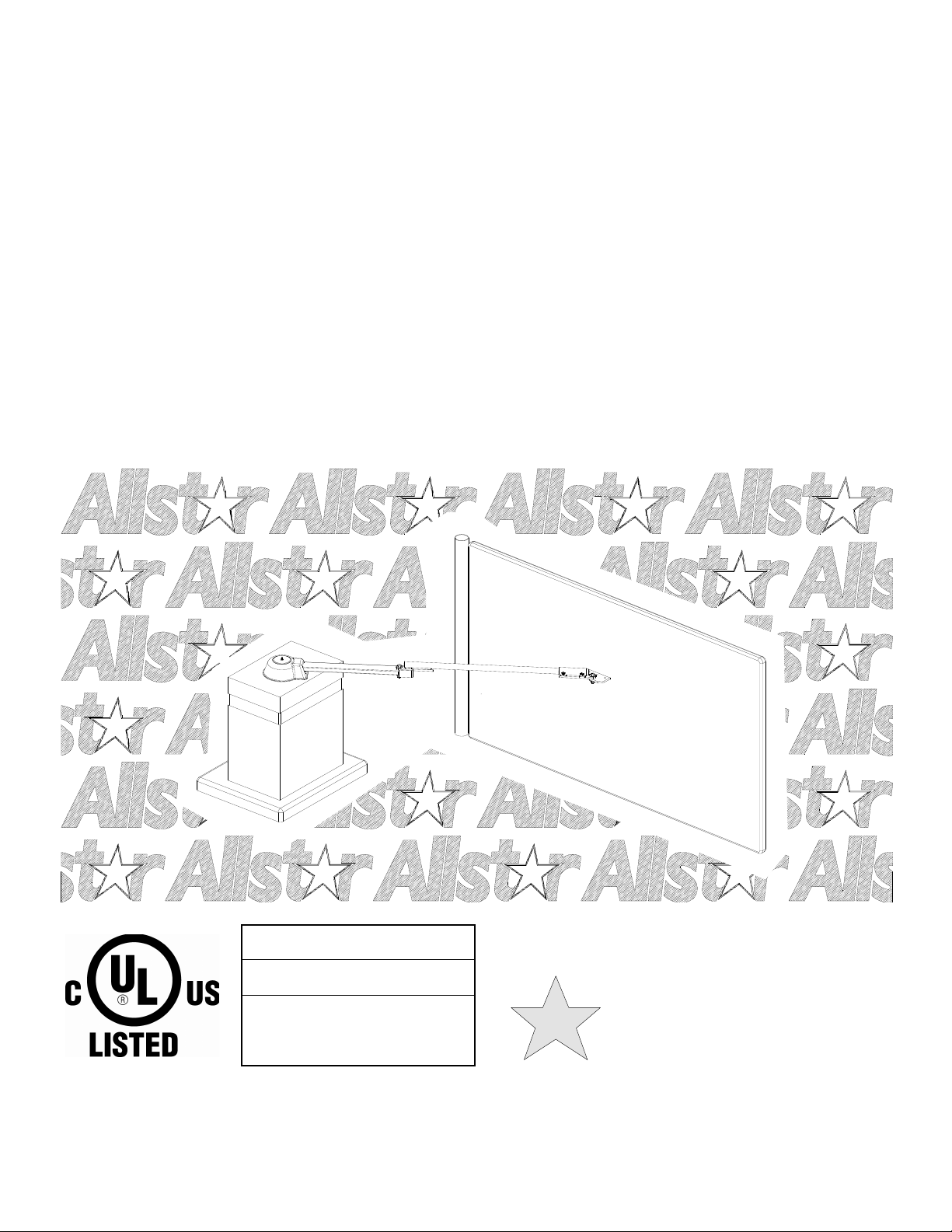
GATE STAR 6000
Model GS6000 - Heavy Duty Commercial
Vehicular Swing Gate Operator
Proven
CGA2K™
TECHNOLOGY!
Serial #:
Date Installed:
Your Dealer:
As of date of manufacture,
meets all ANSI/UL 325
Safety Requirements for
Vehicular gate operators
112538
READ THIS MANUAL
CAREFULLY BEFORE
INSTALLATION OR USE
SAVE THESE INSTRUCTIONS
Page 2
TABLE OF CONTENTS
2
Pre-Installation Notes ...................................................... 3
Operator Class Designation......................................... 3
Section A: Gate System Design/Installation................. 4
Section B: Preparing the Site......................................... 6
The Concrete Operator Pad ......................................... 6
Placing the Vehicle Detector Loops ........................... 6
Electrical Power Requirements ................................... 8
Section C: Installing the Operator ................................. 9
Placing the Mechanical Unit ........................................ 9
Installing the Arm.......................................................... 9
Setting the Limit Switches ......................................... 11
Electrical Hookup........................................................ 11
Connecting the High Voltage AC Wiring .................. 12
Bi-Parting Installation................................................. 12
Accessory Equipment Hookup.................................. 13
Optional Photoelectric Thru Beam Sensor........... 14
Optional Photoelectric Retro-Reflective Sensor.. 15
WARNING HIGH VOLTAGE
ONLY A QUALIFIED TECHNICIAN SHOULD SERVICE THIS GATE OPERATOR
Optional Electric Edge Sensor ...............................16
Pre-Setting the Motor Overload Sensitivity...............18
Setting the Switch Selectable Options ......................19
No Load Test Mode......................................................19
Section D: Starting the Operator ..................................20
Wiring Diagram ............................................................20
Applying Power............................................................21
Indicator Lamps ...........................................................21
Maximum Run Timer ...................................................22
Final Settings ...............................................................23
Terminal Strip Reference Chart..................................24
Section E: End User Instructions .................................25
Safety Guide for the End User....................................25
Operational Guide for the End User...........................27
Manual Release Instructions ......................................28
Operator Exploded View & Parts List .................. 29 & 30
Technical Specifications ................................................32
Figure 1: Test Log
PERIODICALLY TEST SENSITIVITY OF OVERLOAD *** READ MANUAL ***
LOG DATE OVERLOAD TEST
DATE TESTED DATE TESTED DATE TESTED DATE TESTED
DATES OPERATOR
SERVICED
READ THESE STATEMENTS CAREFULLY AND FOLLOW THE
INSTRUCTIONS CLOSELY.
The Warning and Caution boxes throughout this manual are there to protect you and
your equipment. Pay close attention to these boxes as you follow the manual.
WARNING
Indicates a MECHANICAL
hazard of INJURY OR
DEATH. Gives instructions
to avoid the hazard.
Indicates a MECHANICAL hazard
instructions to avoid the hazard.
CAUTION
of DAMAGE to your gate, gate
operator, or equipment. Gives
WARNING
Indicates an ELECTRICAL
hazard of INJURY OR
DEATH. Gives instructions
to avoid the hazard.
CAUTION
Indicates an ELECTRICAL hazard
of DAMAGE to your gate, gate
operator, or equipment. Gives
instructions to avoid the hazard.
Page 3

PRE-INSTALLATION NOTES
3
The Gate Star 6000 (GS6000) Vehicular Gate Operator will provide
convenience and assurance to the ultimate users for many years. It is
ruggedly built of the finest materials and has been thoroughly inspected
and tested at the factory. It has many features that will aid in the
installation and testing of the complete gate system. The GS6000 is
certified to comply with UL Standard for Safety - UL325. (115 Volt
version only).
NOTICE - BEFORE ATTEMPTING INSTALLATION,
READ THIS MANUAL CAREFULLY SO YOU WILL
BE THOROUGHLY FAMILIAR WITH THE
FEATURES OF THE GS6000 AND ITS PROPER
INSTALLATION PROCEDURES
The GS6000 Vehicular Swing Gate Operator is designated a Class I
Residential Vehicular Swing Gate Operator, and is intended to operate
a vehicular swing gate installed on a residential home, maximum of
four single families in the dwelling, or a garage or parking area
associated with that home. The GS6000 vehicular gate operator is also
designated Class II (Commercial location or multi-family home); III
(industrial location not intended to service the general public); and IV
(secure or restricted access locations, ie. airports and prisons). The
GS6000 may be used in any Class location.
Because the GS6000 (as well as gate operators sold by other
manufacturers) is designed to start and move gates weighing as much as
1100 pounds,---the GS6000 is capable of producing high levels of
force. It is important in the design of the total gate system that
designers, installers and users be aware of the hazards that may be
associated with the IMPROPER design, installation and use of
Vehicular Gate systems and Gate Operators.
The gate operator is only one part of a complete automatic gate
operating system. As each location and usage is different, a properly
designed system will include all applicable safety devices.
The GS6000 CGA2K™ Technology provides several features that
can help reduce the hazards of your gate system.
Built-In Overload Detector Sensing System
The GS6000 has a built-in "overload detector" that can help reduce the
hazards of your gate system. This device, however, must not be
considered as the primary defense system. Consider all available
options (electric leading edges, photoelectric sensors, protective screen
mesh, etc) to eliminate hazards in your gate system design.
The GS6000 built-in overload detector will activate if there is an abrupt
increase in motor current above that normally required to move the
gate. The overload detection point is an adjustable setting that must be
determined at the time of installation. This setting must be tested
periodically to ensure proper operation. Diligent maintenance of the
gate hinges and hardware will assure the most responsive operation of
the overload detector. See pages 16 & 20.
ADVISE THE PURCHASER TO CHECK THE SENSITIVITY OF
THE OVERLOAD PERIODICALLY AND LOG THE DATE
TESTED ON THE LOG LOCATED ON PAGE TWO OF THIS
MANUAL (See Figure 1, pg. 2.)
.
The GS6000 is also provided with a Torque Limiter that may be
adjusted to "slip" when an obstruction is encountered. However, the
purpose of the Torque Limiter is to protect the GS6000 mechanical
parts. Whether the overload is activated before the Torque Limiter slips
will depend upon the "tightness" of the adjustment of the Torque
Limiter. This adjustment will be explained in the final check out of the
GS6000.
Connections for External Entrapment Prevention Sensors
Because all gate system installations are different, the GS6000 control
panel provides independent connections for Open and Close noncontact (photoelectric) and contact (edge) sensors. In this way a
photoelectric sensor could be utilized to guard the gate area when
closing and an edge sensor would provide the protection when opening.
Depending on the particular application a combination contact and noncontact sensor protection system for the open and close directions may
provide more effective entrapment protection than a single device for
both directions. See pages 4, 5, 14, 15, 16, 20, 25, 26, and 27.
NOTICE - THE IMPORTANT SAFEGUARDS AND
INSTRUCTIONS IN THIS MANUAL CANNOT
COVER ALL POSSIBLE CONDITIONS AND
SITUATIONS WHICH MAY OCCUR DURING ITS USE. IT
MUST BE UNDERSTOOD THAT COMMON SENSE AND
CAUTION MUST BE EXERCISED BY THE PERSON(S)
INSTALLING, MAINTAINING AND OPERATING THE
EQUIPMENT DESCRIBED HEREIN. DO NOT USE THIS
EQUIPMENT FOR ANY OTHER THAN ITS INTENDED
PURPOSE — OPERATING A SWING GATE.
Audio Alarm and Safe Secure™ Open/Close Push Button Enableon-Alarm Only (Patent No. 6,611,205)
The GS6000 has an audio alarm that sounds when a second occurrence
of the built-in overload activation is registered before an end limit
(open or close) is reached. The alarm continues to sound warning until
a fixed wire input is activated or five (5) minutes pass. As with the
built-in overload detector, diligent maintenance of the gate hinges and
hardware will avoid nuisance operation of the overload detector and
thereby avoid nuisance operation of the audio alarm. The patented Safe
Secure™ Open/Close Push Button Enable-on-Alarm Only feature can
be set to provide a secure control station that will be functional in an
emergency situation. See pages 19 and 20.
SMART™ Self-adjusting MAximum Run Timer
The GS6000 has a Self-adjusting MAximum Run Timer, SMART™.
The amount of time for the first few cycles of operation are registered
and averaged within the motor controller circuitry. After the first few
initial cycles, if the gate is activated and no other command is given or
an end limit (open or close) is not reached in the previously counted
cycle time plus approximately 4 seconds, the operator will be turned
off. See page 22.
OTHER FEATURES
Auto Close Timer: Adjustable from 2 to 60 seconds, provides an
automatic closure of the gate from the full open position. See page 19.
Timer Re-close On/Off Switch: Enables an automatic closure of the
gate from a partially closed position if the close movement was
initiated by the Auto Close Timer and the close cycle was interrupted
by a non-contact (photoelectric) sensor input. See page 19.
Diagnostic LEDs on the Motor Controller Board: Provides a visual
indication of the status of the gate system operation. See page 21.
Page 4
A: GATE SYSTEM DESIGN / INSTALLATION
4
TO REDUCE THE RISK OF SEVERE
INJURY OR DEATH: READ AND FOLLOW
WARNING!
ALL INSTALLATION INSTRUCTIONS AND
GATE SYSTEM DESIGN PARAMETERS!
GATE SYSTEM DESIGN AND INSTALLATION
• The GS6000 operator may be installed on a Class I, II, III, or IV
Vehicular Swing Gate. See page 3 for an explanation of the
different Class locations. See the last page of this manual for the
operator specifications (voltage, maximum gate weight & length
etc.).
• Make sure that the gate moves freely, all hinges are in good working
order, the gate does not bind in any manner and the gate swing area
is clean and free of irregularities. DO NOT INSTALL THE
OPERATOR UNTIL ALL GATE PROBLEMS HAVE BEEN
CORRECTED.
• Do not increase the built-in overload detector adjustment or
overtighten the torque limiter to compensate for a poorly working
gate. A well maintained gate will ensure easy manual operation (if
needed) and maximum operator obstruction sensitivity.
• Install the operator on the inside of the property/fence line. DO
NOT install an operator on the public side of the fence line or gate.
Outward swinging gates should not open into public areas.
• The gate must be installed in a location so that enough clearance is
supplied between the gate and any adjacent structures when opening
and closing to reduce the risk of entrapment.
• Make sure the gate operating system is placed far enough back from
the road to eliminate traffic backup. The distance from the road, size
of the gate, usage level and gate cycle/speed must be taken into
consideration to eliminate potential hazards.
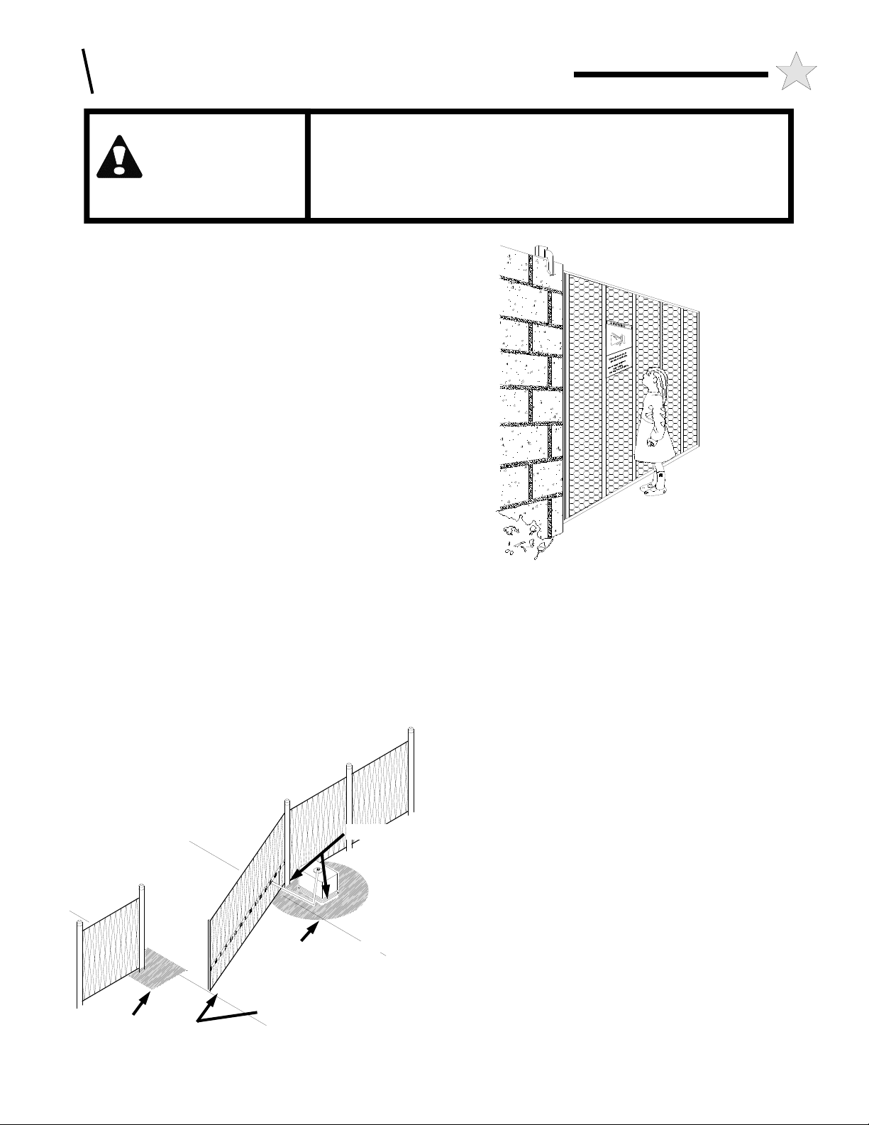
• For ORNAMENTAL “GRILL TYPE” GATES (or any other type of
104932
ENTRAPMENT
SAFETY CHECK LIST:
ZONE
PINCH POINTS
ENTRAPMENT
ZONE
ELECTRIC GATE EDGE
Figure 3
104949
Figure 2
open gate where a handhold or toehold may be achieved), injuries
may occur when people put arms through the openings or children
“ride” the gate by standing on the bars and holding on to the gate.
THIS POTENTIAL HAZARD CAN BE MINIMIZED BY
INSTALLING A MESH SCREEN ON THE GATE. The
manufacturer strongly recommends the entire gate and adjacent
fence area the gate covers when open be meshed or guarded such
that a handhold or toehold cannot be achieved. See Figure 2.
• The gate operator as described in this manual is a VEHICULAR
GATE OPERATOR and as such is NOT INTENDED FOR
PEDESTRIAN traffic. In installations where pedestrian passage
through the fence is necessary, install a pedestrian access opening.
The pedestrian access opening shall be designed to promote
pedestrian usage. Locate the vehicular gate and the pedestrian
access opening such that persons will not come into contact with the
vehicular gate during the entire path of travel of the vehicular gate.
See page 26 for additional information.
• Install leading edge detectors and/or photocells in your design to
protect system entrapment zones. These devices can be provided
for incorporation in your gate system design.
• Use the illustration at left (Figure 3) and the information and
diagrams on pages 14, 15, and 16 to minimize the risk of injury in
your design of the swing gate operator system. IDENTIFY THE
ENTRAPMENT ZONES AND PINCH POINT AREAS IN YOUR
GATE. Design the gate installation to minimize the risk of
entrapment in these areas. Install additional safety equipment such
as edge sensors and photocells to further minimize risk. All
entrapment zones are required to be protected.
• Entrapment Zones: Design in personal entrapment protection
devices to protect people from entrapment in the zones shown in
Figure 3 and the information and diagrams on pages 14, 15, and 16.
Page 5

A: GATE SYSTEM DESIGN & INSTALLATION
• Pinch Points: Use protective measures (guards, padded edges, etc.)
to protect people from the pinch points shown in Figure 3 and the
information and diagrams on pages 14, 15, and 16. Attach roller
guards in cantilevered gate systems to minimize the risk of hands
being caught between the top of the gate and the roller.
• SWING GATES HAVE THE POTENTIAL HAZARD OF HANDS
AND FINGERS BEING PINCHED between the gate edge and the
post to which the gate is mounted. It is recommended that the
hinges be mounted so that this opening increases as the gate swings
open. PROTECT THIS "PINCH POINT" SO THIS HAZARD
IS AVERTED. See Figure 3.
• CONSIDER ALL OTHER "PINCH POINTS" IN YOUR DESIGN
of the gate system. Observe the arm as it opens and the two arm
pieces swing past each other. Use protective measures to reduce
hazards at this location. Restrict access to the arm motion. See
Figure 3.
• DO NOT consider the built-in overload detector as the primary
defense system. Consider all options in the gate system design.
• DO NOT connect any auxiliary equipment to the GS6000 (detectors,
card readers, etc.) until the gate operator and all its functions are
fully tested. Only connect one device at a time and ensure its proper
function(s) before moving on to the next device.
• DO NOT locate any control device (key switch, switch, key pad,
card reader, etc.) in a position where it may be activated by a person
reaching through the gate or while touching the gate in any manner.
Locate all control devices a minimum of 10 feet from the gate when
opened or closed.
• Outdoor or easily accessible controls must be of the security type to
prevent unauthorized use of the system.
• Install all devices that will Open, Close or Stop the gate in such a
manner that THE GATE WILL BE IN FULL VIEW WHEN THE
DEVICE IS OPERATED.
• Before activating the "timer to close" option of the GS6000,
ENSURE THE PERSONAL ENTRAPMENT PROTECTION
DEVICES (operator reversing feature, edges, photocells) ARE
OPERATING and install VEHICLE DETECTOR LOOPS AND
VEHICLE DETECTORS for protection of user vehicles. Read the
manual for information on the installation of these devices. IF
VEHICLE DETECTOR LOOPS HAVE BEEN INSTALLED TO
PREVENT THE GATE FROM CLOSING ON A VEHICLE,
INSTRUCT THE USER TO PERIODICALLY CHECK THE
OPERATION OF THE DETECTORS.
• USE EXTREME CAUTION WHEN WORKING NEAR THE
BELTS AND PULLEYS when the operator cover is removed.
Apply power to the operator only when instructed to do so.
• When the GS6000 cover is removed, high voltage is exposed in the
control box area. EVEN IF THE RED POWER LIGHT IS NOT
LIGHTED, HIGH VOLTAGE AC MAY STILL BE PRESENT.
NEVER LEAVE THE INSTALLATION WITH THE COVERS
REMOVED.
• ALWAYS TURN OFF THE POWER BEFORE ATTEMPTING
SERVICE OF EITHER THE ELECTRICAL OR MECHANICAL
SYSTEMS.
• SECURELY ATTACH THE WARNING SIGNS provided with the
GS6000 on the gate (one on the outside and one on the inside) where
they can be seen by persons in the area of the gate to alert them of
automatic gate operation. (If the user refuses to have the warning
signs installed, Allstar recommends that you note this on your
5
records and have the user sign a disclaimer.) See Figure 4.
MOVING GATE
CAN CAUSE
SERIOUS
INJURY OR
DEATH
KEEP CLEAR !
Gate May Move at Any Time.
Do not allow children to play
in gate area or operate gate.
Operate gate only when gate
area is in sight and free of
people and obstructions.
Figure 4
AS THE INSTALLER YOU ARE RESPONSIBLE FOR:
1 ASSURING THAT THE GATE AND OPERATOR SYSTEM,
WHEN FULLY INSTALLED AND OPERABLE, COMPLIES
WITH ALL APPLICABLE REQUIREMENTS OF UL325:
STANDARD FOR SAFETY FOR DOOR, DRAPERY, GATE,
LOUVER AND WINDOW OPERATORS AND SYSTEMS.
2 ASSURING THAT THE OWNER/END USER OF THE
SYSTEM UNDERSTANDS ITS BASIC OPERATION AND
SAFETY FEATURES. IN PARTICULAR, BE SURE THE
OWNER/END USER UNDERSTANDS THE LOCATION
AND OPERATION OF A MANUAL DISCONNECT
(WHERE PROVIDED) OR HOW TO OPERATE THE GATE
MANUALLY.
3 YOU ALSO HAVE THE PRIMARY RESPONSIBILITY OF
INSURING THAT ALL POSSIBLE OPERATIONAL
HAZARDS HAVE BEEN CONSIDERED AND
ELIMINATED. YOU MUST ADVISE AND WARN THE
PURCHASER AND THE ULTIMATE USER OF ANY
HAZARDS THAT YOU HAVE NOT BEEN ABLE TO
ELIMINATE.
4 POINTING OUT TO THE OWNER/END USER OF THE
GATE SYSTEM THAT CHILDREN OR PETS ARE NOT
ALLOWED TO PLAY ON OR NEAR THE GATE, FENCE
OR ANY PART OF THE SYSTEM, AND THAT THE
SAFETY INSTRUCTIONS SUPPLIED WITH THIS
OPERATOR AND THEIR IMPLEMENTATION ARE THE
RESPONSIBILITY OF THE OWNER/END USER.
5 LEAVING THE INSTALLATION AND MAINTENANCE
MANUAL FOR THIS OPERATOR AS WELL AS ANY
ADDITIONAL SAFETY INFORMATION SUPPLIED WITH
THIS OPERATOR OR OTHER COMPONENTS OF THE
GATE SYSTEM WITH THE OWNER/END USER.
6 NOT PLACING IN SERVICE THIS OPERATOR IF YOU
HAVE ANY QUESTIONS ABOUT THE SAFETY OF THE
GATE OPERATING SYSTEM. CONSULT THE
OPERATOR MANUFACTURER.
104880
Page 6
3
28-3/4
30
24
6
B: PREPARING THE SITE
THE CONCRETE PAD
The standard GS6000 is designed to operate a single leaf gate.
Installation requires the presence of a suitable concrete pad as a base for
the operator. The dimensions of this pad should be sufficient to allow
at least 3" of clearance from each edge of the pad to the nearest
operator mounting hole. The top of the pad should be 3" above grade to
raise the operator above any standing water, while the depth of the pad
below grade is dependent on the weight and size of the gate and the soil
conditions at the site of the installation. THE SITE FOR THE
OPERATOR SHOULD BE CHOSEN WITH AT LEAST 26" OF
CLEARANCE ABOVE THE TOP OF THE UNIT TO ALLOW FOR
COVER REMOVAL.
Hinge Pivot Point
Closed Gate
24"
12.38"
42"
30"
Output
Shaft
Target Area
Conduit Exit
From Pad
10" W x 5" H
16"
If no suitable concrete base exists, a pad must be poured. After
completing the gate installation, place the operator pad at the
appropriate location as illustrated in Figures 5 and 6. Consult
local building codes for depth of base. Typical depths range
from 24” to 36”. In either case, if vehicles are going to be
operated in the vicinity of the operator, consider installation
of protective bollards in front of the operator.
Operator Pad
112315
16 1/4"
Figure 5: Operator
F o o t p r i n t
To properly install a bi-parting gate system, it is necessary to use two
(2) GS6000 operators in your design, one unit on each side of the
opening. The operators can be linked via the control circuitry for
Primary/Secondary (Master/Slave) operation. It is necessary to run an
additional low voltage conduit between the two units.
If desired, the service conduits can be routed up through the concrete
pad. The conduits should exit the concrete pad in the 5” x 10” target
area as illustrated in Figure 5. The end of the conduits should protrude
a maximum of one (1) inch above the concrete surface.
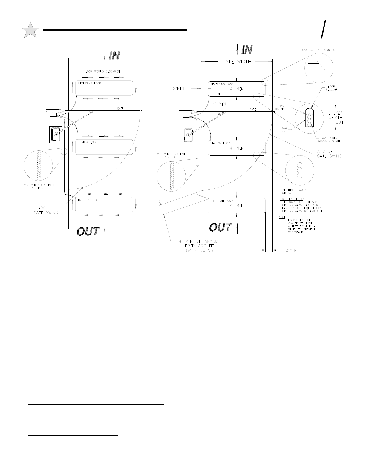
PLACING THE VEHICLE DETECTOR LOOPS
If Vehicle Detectors are to be used with the GS6000, the "Loops" to be
buried in the drive should be installed during the site preparation phase
of the installation. Proper placement of the Vehicle Detector wire loops
is critical if the loops are to provide satisfactory, extended service.
THE MOST IMPORTANT CONSIDERATIONS ARE: 1) PROPER
WIRE TYPE AND, 2) GOOD, TIGHT CONNECTIONS FROM THE
LOOP TO THE LOOP TERMINATING CONNECTOR. The
termination of the loop wires will be at the GS6000 terminal board.
There are three pre-wired Vehicle Detector sockets provided in the
GS6000 operator (detector modules not supplied as standard). These
sockets are powered by 24 VAC supplied by the operator. If you as the
installer utilize these socket adapters you must provide the detector
modules and loop wiring. The loop detector modules supplied should
be compatible with the sockets (11 pin round socket connector) and
rated voltage (24 VAC). If additional loop detectors are used a separate
A/C service must be provided for the detectors.
Two different types of Loop Installations will usually be encountered
when placing the loops in the drive: 1) If the driveway material is
already in place. saw cuts will be needed in which to place the loop
wire. 2) For loops where the paving material will be installed after the
loop is positioned, it is necessary that the loops be placed in Schedule
40 PVC pipe to maintain uniform loop spacing with respect to the
surface of the pavement. The loop should be placed 1.5" below the
surface of the pavement and at least 2" above any reinforcing steel.
112538
24”
28-3/4”
3”
NOTE: SEE PAGE 10 FOR
PLACING THE OPERATOR AND
GATE ARM ASSEMBLY
INSTRUCTIONS AND
ILLUSTRATIONS
30”
Figure 6: Operator Layout
Page 7
B : PREPARING THE SITE
7
Figure 7: Loop Diagrams
The lead-in wires need not be in PVC, but must have a least six (6)
twists per running foot.
THE LOOP WIRES MUST BE CONTINUOUS. NO SPLICES OR
CONNECTIONS IN THE LOOP ARE TO BE PERMITTED
BELOW GROUND. THE ONLY CONNECTION WILL BE AT
THE TERMINATION OF THE WIRE AT THE VEHICLE
DETECTOR. Above ground splices may be used providing the wire
is twisted, soldered and moisture sealed. For best long term results,
do not use wire nuts anywhere in the loop system. Connect to the
Vehicle Detector harness by soldering.
For saw-cut installations, observe the methods recommended in
Figure 7, above. The saw-cut must be to a depth of 1.5", clean and
with no sharp corners. After placing the wires, it is essential that the
wires be held tightly in place by a foam backing prior to pouring the
sealant. THIS IS ESPECIALLY IMPORTANT WHEN FREEZING
IS LIKELY. No voids should exist that will permit the collection of
water that might freeze and push the loop wires out of the slot. The
sealant used should not be hard setting and should be suitable for
pavement material.
THE WIRE USED FOR THE LOOPS MUST BE HEAT AND
WATER RESISTANT, CROSS-LINK POLYETHYLENE
INSULATED. TYPE XLPE IS BEST. RHW IS O.K. DO NOT
USE ANY PVC INSULATED WIRE. (PVC insulation will absorb
moisture that may affect Detector operation.) WIRE SIZE SHOULD
BE #16 GA. STRANDED OR LARGER.
104945
VEHICLE DETECTOR SHADOW LOOP
(BLANKING LOOP) FOR SWING GATES
The inside loop for a swing gate installation must be located at least
4 feet outside of the arc of the gate. If it is not, the Vehicle Detector
may detect the gate as it moves over the loop and cause the Gate to
reopen. If the gate is large and a single leaf, the arc usually requires
that the loop be a considerable distance from the closed gate position.
This may not be an effective position for the loop. In this case, a
“shadow” or “blanking” loop may be used.
When a Shadow Loop is necessary, connect the loop wires to the
operator terminals G and E, (Shadow Loop) and insert a loop
detector module in the Shadow Loop socket (black, white, blue,
yellow connector wires). The GS6000 circuitry will recognize a
vehicle on the loop and prevent the gate from closing while the
vehicle is over the Shadow Loop. When the gate is closing or
opening, the GS6000 circuitry will ignore input from this loop as the
gate swings over it.
Page 8
8
B: PREPARING THE SITE
110112
SINGLE GATE
WIRE
DISTANCE
SIZE
100 FT
#14
150 FT
#12
250 FT
#10
400 FT
#8
600 FT
#6
NOTE: DISTANCE IS T OTAL LENGTH OF
WIRE FROM CIRCUIT BREAKE R IN THE
MAIN PANEL TO THE GATE OPERATOR.
Table 1
AC POWER SOURCE
TYPICAL CONNECTIONS
DOUBLE GATE
WIRE
SIZE DISTANCE
50 FT
#14
75 FT
#12
125 FT
#10
200 FT
#8
300 FT
#6
HIGH VOLTAGE TERMINALS
GND
120 VAC, 15A
Dedicated Circ uit
L2 L1
ELECTRICAL POWER REQUIREMENTS
The GS6000 can be ordered for 115 Volts AC (VAC) or 230 VAC
operation. The AWG wire size for the electrical service depends on
the distance of the operator from the breaker panel. Refer to Table 1
to determine the correct wire size.
The DISTANCE column is the ideal distance from the breaker panel
to the operator for a given wire size and voltage.
NOTE! FOR A BI-PARTING INSTALLATION, THERE
WILL BE TWO OPERATOR UNITS OPERATING AT THE
SAME TIME. IF THESE WILL BE POWERED FROM THE
SAME SUPPLY IT WILL BE NECESSARY TO REDUCE THE
LENGTHS IN TABLE 1 BY A FACTOR OF TWO.
Class 2 low voltage wiring from external controls such as a key pad,
card reader, telephone entry device, etc. must be brought to the
GS6000 by a separate conduit from the 115 VAC electrical hook up
conduit. Low voltage control wires MUST NEVER be routed in the
same conduit as the HIGH VOLTAGE power wires.
WARNING!
AVOID ELECTROCUTION:
DO NOT ROUTE LOW VOLTAGE WIRES IN SAME
CONDUIT AS HIGH VOLTAGE WIRES. FOLLOW
ALL LOCAL ELECTRICAL CODES OR THE
NATIONAL ELECTRICAL CODE.
Note! If a wire set (connections between Master Open and
Master Close (Primary/Secondary operation terminals) is to
routed between a set of GS6000 operators for bi-parting
operation these wires ARE LOW VOLTAGE WIRES AND
MUST BE ROUTED IN A LOW VOLTAGE CONDUIT
TO THE CONTROL BOX.
OTHER VOLTAGES AND 3 PHASE SYSTEMS.
The GS6000 can operate at other voltages or on three (3) phase
systems. To operate at 440 VAC it will be necessary to install an
external step down transformer. The transformer should be located
in a separate electrical box and protected by suitable circuit breaker
and/or fusing. A 440 Volt rated switch should also be installed.
Follow local electrical codes or the National Electrical Code. The
transformer selected should be UL LISTED and be rated for a
minimum 600 Volt-Amperes (Watts).
IF TWO OPERATORS ARE TO BE USED FOR A BI-PARTING
GATE SYSTEM, THEN A 1000 VOLT-AMPERE/WATT
TRANSFORMER MUST BE USED.
Operating from a three (3) phase line will require the use of a 230
VAC rated GS6000, CHECK THE OPERATOR PRODUCT
LABEL!!! The GS6000 (rated for 230 VAC) may be operated from a
230 Volt "Delta" or "Y" line. In either case, ONLY one "leg" of the
three phase line will be used. The unbalance of the line will be
minimal since the full rate current of the GS6000 at 230 VAC is only
2.2 amperes. (4.4 Amperes for a bi-parting system.) Connect any
two wires of the three phase system to the 230 VAC GS6000. Tape
the third wire carefully so that it does not short to any other object.
(The "Y" system will have 4 wires, one of which will be the
"common". Make sure the common is NOT selected as one of the
wires connected to the GS6000.) It is always best to also pull a
ground wire from the electrical service box to the GS6000 to ensure
the frame is securely affixed to GROUND.
SERVICE CONDUIT
For new installations the conduit for the High Voltage may be
brought to a junction box near where the GS6000 will be located or it
may be brought directly to the GS6000’s Control Box.
UNPACKING
CHECKLIST
The GS6000 as shipped consists of the
components listed below.
GS6000 Operator
Wood Pallet with 4 lag bolts
Instruction Kit
Instruction Manual
Warning signs
Swing Arm Kit
Swing Arm
Crank Arm
Crank Arm Extension
Swing Gate Fittings
Swing Arm Bracket
Swing Arm Padlock with keys
Hardware Package
Page 9

C: INSTALLING THE OPERATOR
TOOLS REQUIRED
The following tools and materials are required for a proper installation of the GS6000. The listing below is minimum list
and not meant as definitive, allow experience to dictate if a task can be better accomplished with a different tool.
1. Wire cutter, stripper and crimping tools. (For attaching accessory equipment to the control box barrier strip.)
2. A #2 Phillips Head screw driver for removing the screws to the High Voltage cover.
3. Medium standard straight blade screw driver for the terminal strip screws.
4. Very small blade screwdriver. (For adjusting the potentiometer on the Logic and Power board.)
5. Electric arc welder or an electric drill with a 3/8" bit. (For attaching Arm Bracket to the Gate.)
6. Several feet of #18 or #22 gauge insulated multistrand wire. (For connecting accessory equipment to the control
box terminal strip, and for limit switch control wires.)
7. Four 1/2" diameter concrete anchor bolts with hex nuts, flat washers and lock washers. (For attaching the GS6000
to the concrete pad.) (Not Included)
8. Concrete drill and bit. (To drill mounting holes for concrete bolts.)
9. Multimeter. (To test line voltage and other measurements as necessary.)
10. Small level. (To level GS6000 at installation.)
11. Hex Key set (5/16” and 1/8” hex key specifically needed)
11. Torque Wrench and 1-5/8” Socket
9
PLACING THE GS6000 OPERATOR
Remove the turret cover and rain seal from the shaft of the
GS6000. SAVE THEM! Next, remove the cover from the GS6000
by removing the 5/16 inch diameter bolts on each side of the unit
and set them aside. SAVE THEM! The operator cover, rain seal
and turret cover are to be re-installed in reverse order of removal at
the completion of the installation.
The recommended procedure for attaching the GS6000 to the
concrete pad is first to locate and drill the hole for the mounting hole
nearest to the gate post. Locate this hole by referring to Figures 5
and 6 (Page 6) and Figure 8 (Page 10). Figure 5 features an aerial
view of the operator footprint and concrete pad outline for a left-
hand mounted GS6000 operator with gate. Figure 6 features an
isometric view of a left-hand mounted GS6000 operator with gate.
Figure 8 features an aerial view of a right-hand mounted GS6000
operator with gate and an isometric view of the gate arm assembly in
a exploded fashion . All dimensions are applicable to either the lefthand or right-hand views, transpose them as necessary to your
particular installation.
Ensure the operator is placed on the
concrete pad such that the center of the output shaft is 42”
vertically and 16” horizontally away from the gate center
hinge point, as illustrated in Figure 5. These are the
critical dimensions for this part of the installation.
After drilling, place an anchor bolt in the initial hole, then reset the
operator mounting hole over that bolt. Measure, re-measure, align,
mark and drill the remaining three holes, again referring to Figures
5, 6 and 8. This can be accomplished with the operator in place or
moved temporarily to the side if desired.
Before tightening the concrete anchor bolts, make sure the GS6000
is level. If any corners of the GS6000 are resting above the concrete
pad, flat washers may be inserted under the frame rails. With the
operator sitting level on the concrete pad, place the anchor flat
washers, lock washers and nuts on the anchor bolts and tighten
securely.
If 1/2" diameter anchor bolts are used, the 3/4" mounting holes on
the GS6000 will allow some adjustment for desired alignment.
TO REVIEW: Make sure the correct position of the GS6000 from
the center line of the gate hinge pivot point to the center line of the
GS6000 output shaft is in accordance with the drawing of Figure 5.
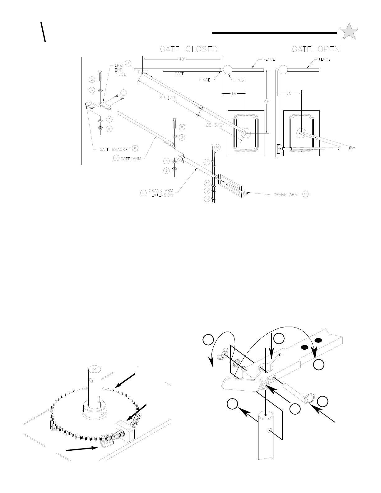
INSTALLING THE GS6000 ARM
Temporarily locate the Gate Bracket on the gate with C-clamps
or by tack welding. The gate bracket is installed to the gate so
the gate arm will be level when connected to the GS6000 output
shaft. See Figure 6 on page 6 and Figure 8 on page 10 for
positioning of the Gate Bracket. The 28-3/4” dimension as
referenced in Figure 6 assumes a pad height of 3” above ground.
Adjust the placement of the gate bracket on the gate at such a
height that corresponds with the height of the concrete pad (add
to the 28-3/4” dimension if the pad is higher than 3”, subtract if
The 40” horizontal dimension referenced in
lower.
Figure 8 and the 28-3/4” dimension referenced in
Figure 6 are the critical dimensions for this part of the
installation.
bracket will be permanently mounted after the gate arm is
assembled and installed. Move the gate to it’s fully closed
position and temporarily immobilize the gate in that position.
Again this is a temporary placement, the gate
Page 10
10
C: INSTALLING THE OPERATOR
HARDWARE LEGEND
Arm End Piece
1
(1 EA) 1/2-13 x 2
2
Hex Head Bolt
(4 EA) 1/2 Flatwasher
3
(2 EA) 5/16-18 X 5/8L
4
SQ Head Set Screws
(2 EA) 1/2-13 Nylock
5
Locknut
Gate Bracket
6
Gate Arm
7
(1 EA) 1/2-13 X 2-3/4”
8
Hex Head Bolt
Crank Arm Extension
9
(2 EA) 1/4 -20 X 1-1/2”
10
Hex Head Bolt
(4 EA) 1/4 Flat Washer
11
(2 EA) 1/4 INT TOOTH LOCK WASHER
12
(2 EA) 1/4-20 Keps Washer Hex Nuts
13
Operator Crank Arm
14
Loosen the adjustment nut of the Torque Limiter located on the top
of the Gear Box on the GS6000 sufficiently to allow the large drive
sprocket and output shaft to turn without back driving the gear box,
v-belt and motor (see exploded view at back of this manual, the
Torque Limiter adjustment nut is the top component of Part No.
010217). This is done by first loosening the small set screws
(5/64” hex key required) on the adjustment nut facings and then
loosening the nut (1-5/8” hex socket or wrench).
At this time also loosen the Stop Pall that is mounted to the large
output drive sprocket (see Figure 9 below), this requires a 1/8” hex
key tool.
Attach the Crank Arm to the Output Shaft by fitting the arm’s large
circular opening onto the shaft, see Figure 10, Action A. Slide the
crank arm onto the operator’s output shaft such that the slot on the
arm is roughly parallel with the closed gate. The crank arm should
be pointing towards the bracket on the gate.
Turn the output shaft so that the hole to mount the clevis pin is
lined up with the hole in the crank arm. Insert the clevis pin fully
through the hole in the crank arm, the hole in the output shaft and
extend through the other side of the crank arm, see Figure 10,
Action B. The ring on the clevis pin should be on the gate side of
the crank arm when fully inserted.
112629
Figure 8: Arm Assembly Illustrations & Positions
** HARDWARE NOT TO SCALE **
At this time insert the release handle/bolt assembly into the outer
through hole on the crank arm, see Figure 10, Action C. The
release handle/bolt assembly is inserted such that it points away
from the gate. Place the 3/8 internal tooth lock washer onto the
bolt end and screw on the 3/8 wing nut finger tight, see Figure 10,
Action D. As you are tightening the wing nut hold the handle such
that it is pointing away from the crank arm. Tighten the wing nut
as tight as possible with finger pressure.
Rotate the release handle 180 degrees such that it is parallel and
pointing in the same direction as the crank arm, see Figure 10,
Action E. This action completes the installation of the crank arm
to the output shaft. Ensure the arm is tight on the shaft.
As shown in Figure 8, attach the Crank Arm Extension to the
Crank Arm with the (2) 1/4-20 x 1-1/2” long bolts, (4) 1/4 internal
tooth lock washers, and (2) 1/4-20 keps washer hex nuts, (Items 9
through 13) provided. For a standard installation use the two holes
D
A
112235
STOP
Figure 9: Stop Pall
DRIVE
SPROCKET
STOP PALL
B
E
112088-01
B
C
Figure 10: Crank Arm Attachment
Page 11

C: INSTALLING THE OPERATOR
11
in the crank arm closest to the end that mounts to the output
shaft. The overall length of the crank arm w/extension is now
25-5/8” from the center of the Output Shaft to the center of the
pivot at the “elbow.” Note that the crank arm w/extension if
required is adjustable and can be lengthened to a maximum of
31-5/8” long in (4) 1.5” increments. This may be required if the
gate bracket cannot be mounted in the position as previously
described. The prescribed installation procedure would be to
follow as outlined in these paragraphs, making adjustments as
needed.
Assemble the gate arm as shown in Figure 8, sliding the arm end
piece onto the end of the arm tube and tightening the 5/16-18 x
5/8 long square head set screws. Again as a matter of note, the
gate arm can be shortened (if necessary due to the gate bracket
placement, etc.) by cutting off a length from the tube. Attach the
gate arm to the crank arm extension and the gate bracket using
the 1/2-13 x 2 bolt (at gate bracket), the 1/2-13 x 2-3/4 bolt (at
the crank arm extension), the four 1/2 flat washers and two 1/213 nylock hex nuts as shown in Figure 8. The gate arm is now
fully assembled with a total length of approximately 67-3/4”
With the Gate still immobilized in the closed position, the
"elbow" will be up against the closed position stop on the Crank
Arm Extension. At this time adjust the placement of the gate
bracket and/or the length of the crank arm/extension or gate arm
to ensure when the gate is fully closed the arm is in a straight
and locked position (from output shaft to gate bracket) as shown
in the left illustration in Figure 8.
Move the Gate to the fully open, 90 degree position as shown in
the right illustration in Figure 8. The crank arm/extension
should fold back over the arm as shown. If it doesn't, some
adjustment of the gate bracket or operator position may be
necessary. With the gate in the fully open position, adjust the
stop pall on the sprocket against the stop on the GS6000 frame
and tighten the set screw. Open and close the gate several times
until you are satisfied that the arm position is correct.
Finish welding or bolting the Gate Bracket to the Gate and
remove the C-clamps.
SETTING THE LIMIT SWITCHES
If you are resetting or checking the Limit Switches the cover must be
removed from the GS6000 operator, follow the procedure as outline
on page 28, to remove the gate arm from the output shaft then see the
first paragraph under PLACING THE GS6000 OPERATOR on
Page 8 to remove the cover. Reconnect the arm (if applicable) and
position the gate at it’s FULLY CLOSED position. If this is an
original installation the torque limiter adjustment nut is still
loosened, if resetting use the OPEN, CLOSE, and STOP buttons to
place the operator into position. Temporarily immobilize the gate in
this FULLY CLOSED position.
If this is a right hand (RH) installation (as shown in Fig. 8) the upper
switch is the Close limit switch, if this is a left hand (LH) mounted
operator (as shown in Fig. 6) the lower switch is the Close limit
switch. Referring to Fig. 11, loosen the clamping screw and nut and
the set screw on the Limit Switch Cam for the appropriate switch.
Rotate the cam on the output shaft (clockwise as you look at the shaft
from the control box if RH mounted, CCW if LH mounted) until it
engages the Limit Switch and an audible “click” is heard. If resetting
and the operator is under power the LED indicator on the control
board can be used as an additional indicator that the switch has
activated. Repeat this several times until you are confident that the
position of the cam is such that the Limit Switch is just closed.
106304
UPPER
LIMIT
CAM
UPPER
LIMIT CAM
CLAMPING
NUT
Figure 11: Limit Switches
Carefully tighten the nut on the Limit Switch Cam. Snug the set
screw on the cam against the output shaft to protect the cam from
accidental movement.
Remove the temporary immobilization from the gate and open the
gate to it’s FULLY OPEN position. Repeat the setting procedure
for the remaining Limit Switch and Cam, ensuring to rotate the Limit
Cam in the opposite direction from the rotation in the previous
paragraph, also see Figure 11.
If resetting or checking the Limit switch settings at this time reinstall
the operator cover and turret, reversing the removal procedure. If
this is an original installation, tighten the Torque Limiter adjustment
nut to an initial setting of 35 ft lbs and retighten the small set screws
on the nut facings.
UPPER LIMIT
SWITCH
LOWER LIMIT
SWITCH
SET SCREW
LOWER LIMIT
CAM
LOWER
LIMIT CAM
CLAMPING
NUT
WARNING!
RISK OF ELECTROCUTION
DO NOT BEGIN THE ELECTRICAL CONNECTION
PROCEDURES UNTIL THE POWER IS TURNED
OFF AT THE CIRCUIT BREAKER
ELECTRICAL HOOK UP
The GS6000 electrical connection is made in the CONTROL BOX
area, see Figure 12. Run a flexible water tight conduit from the
service junction box to the GS6000 CONTROL BOX. Route three
#14 wires (minimum size) from the service junction box in this
conduit to the GS6000 Control Box. If the GS6000 is wired for 115
Volts, route a black, white and green or ground wire. If the GS6000
is wired for 230 Volts, route a black, red and green or ground wire.
If the conduit has been pre-placed in the cement pad route these
wires (again using flexible conduit) up through one of the large holes
in the bottom operator plate and connect to the conduit hole on the
right side of the CONTROL BOX area.
Page 12

12
C: INSTALLING THE OPERATOR
CONNECTING THE AC WIRING
115 VOLT INSTALLATIONS:
Before beginning to wire in the power supply
connections, ensure the power in turned off at
the service supply box and also ensure the
operator On/Off switch is in the Off position.
Starting at the GS6000 Control box there are three wires (black,
wihte, and green) protruding from the lower hole of the Control Box
On/Off Switch / Outlet box. These wires can additionally be
identified as they are capped off with large orange wire nuts. It is not
necessary to remove the On/Off Switch / Outlet cover. Proceed as
follows:
1. The BLACK
service conduit, normally also a black wire.
2. The WHITE
the service conduit, normally also a white wire.
3. The GREEN wire attaches to the green or GROUND wire from
the service conduit.
wire attaches to the 115 VAC HOT wire from the
wire attaches the 115 VAC NEUTRAL wire from
230 VOLT INSTALLATIONS:
Note: in 230 VAC wiring systems, there will be two "HOT" wires,
normally a red and a black wire. If there is a white wire, typically it
will be a neutral wire. Starting at the GS6000 there are three wires
(black, red, and green) protruding from the lower hole of the Control
Box On/Off Switch / Outlet box. These wires can additionally be
identified as they are capped off with large orange wire nuts. It is not
necessary to remove the On/Off Switch / Outlet cover., Proceed as
follows:
1. The BLACK
from the service conduit, normally also a black wire.
2. The RED
red.
3. The GREEN wire attaches to the green or GROUND wire from
the service conduit.
PROPER OPERATION OF THE SURGE PROTECTORS
MOUNTED ON THE GS6000 CONTROL BOARD DEPENDS
UPON A SOLID GROUND. ALSO, UL LISTING REQUIRES
THAT THE GS6000 FRAME BE GROUNDED.
wire attaches to one of the 230 VAC HOT wires
wire attaches to the other 230 VAC HOT wire, normally
WARNING!
protect against all strikes, additional protection will substantially
reduce the occurrence of lightning damage. Industry data indicates
that the most lightning strikes attempt to enter an appliance through
the power lines. Effective protection requires that the surge current
from the lightning strike be shunted to ground. This must be done
without raising the potential of the circuitry in the GS6000, with
respect to ground, to the levels that will damage the solid state
circuitry. Lightning strikes generate enormous currents for very
short periods of time. Unfortunately, the period of time is long
enough to damage solid state components and many times, other
components. The key to success is a very low resistance path from
the surge protector to ground for these currents in addition to a surge
protector that will act fast enough to protect the solid state circuitry.
Several manufacturers offer suitable surge protectors.
RIGHT HAND AND LEFT HAND INSTALLATION
The GS6000 Control panel is configured at the factory for right hand
operation - where the operator is mounted to the right of the gate leaf
as you look at the installation from the inside (secured side, as shown
in Fig. 8).
For left hand operation - (the operator is mounted to the left of the
gate leaf as you look at the installation from the inside or secured
side, reference Fig 6) - move the 8 pin high voltage harness
connector (white) and the 3 pin limit harness connector (orange)
from the right hand connector blocks on the control board to the left
hand connector blocks, see Figure 12, below.
110134
LOCATION OF
RIGHT-HAND &
LEFT HAND
HARNESS
CONNECTIONS
LIMITS
HIGH VOLTAGE
TO REDUCE THE RISK OF DAMAGE DUE TO
LIGHTNING, ENSURE A SOLID GROUND FROM
THE GS6000 GROUND WIRE IN THE SERVICE
ENTRANCE TO THE ELECTRICAL SERVICE
GROUND OR TO A EARTH GROUND STAKE
NEAR THE GS6000.
ADDITIONAL LIGHTNING PROTECTION
For those areas where a high probability of ground lightning strikes
exists (Florida, Georgia, etc,) additional lightning protection should
be installed in the GS6000. Although it may not be possible to
Figure 12: Right/Left Hand Control Board Connectors
PRIMARY/SECONDARY (Bi-Parting)
INSTALLATION
For a Primary/Secondary installation where there are two gate leaves
and two operators, an additional conduit is installed between the
primary operator and the secondary operator. Both operators must be
wired for AC power (as previously described) but share a common
set of input controls, accessory equipment and (where applicable)
external entrapment protection devices. When properly connected
and configured, an input made to the control system of the Primary
operator will result in an identical reaction from the Secondary
Page 13

N
C: INSTALLING THE OPERATOR
13
PRIMARY OPERATOR
TERMINAL STRIP
16
COMMON
MASTER CLOSE
15
M. CLOSE
MASTER OPEN
14
M. OPEN
BI-PARTING WIRING: PRIMARY/SECONDARY UNITS
Figure 13: Primary/Secondary
SECONDARY OPERATOR
TERMINAL STRIP
16 COMMO
8
STOP
7
CLOSE
6
OPEN
110145
operator. For this installation, one operator must be mounted and
configured for Left Hand operation and the other mounted and
configured for Right Hand operation. For configuration see paragraph
directly preceding , for an illustration of LH mounting see Fig. 6, page 6
and for an illustration of RH mounting see Fig. 8, page 10.
In general, all of the instructions that precede and follow this section
concerning installation of individual operators are applicable in a
Primary/Secondary application except as follows:
Choose one of the operators to be the PRIMARY and the other to be the
SECONDARY. Route all of the control wiring and accessory wiring to
the PRIMARY operator only. This will prevent grounding loop
problems which can occur when more than one COMMON or ground
wire is attached between separate operators. All accessory equipment
should also be wired to the PRIMARY operator. An exception to this
rule would be if the Secondary operator had a unique entrapment
protection zone, then that device’s output is wired directly to the
Secondary operator.
Connect terminal #14 (M. OPEN) on the PRIMARY operator to
terminal #6 (OPEN) on the SECONDARY operator. Connect terminal
#15 (M. CLOSE) on the PRIMARY operator to terminal #7 (CLOSE)
on the SECONDARY operator. Connect terminal #16 (COMMON) on
the PRIMARY operator to terminal #16 (COMMON) on the
SECONDARY operator . Use conduit separate from AC power
service. See Figure 13 for the correct wiring.
The last step to complete the Primary/Secondary operator configuration
is to set the Switch Selectable Options to Primary/Secondary mode as
outlined on page 22.
WARNING!
RISK OF ELECTROCUTION
DO NOT BEGIN TO SET THE FOLLOWING
ADJUSTMENTS UNTIL THE POWER IS TURNED
OFF AT THE GS6000 CONTROL BOX
ACCESSORY EQUIPMENT HOOK-UP
IMPORTANT - remove power from the operator before attempting
to connect an accessory device or control station.
All accessory equipment is connected to the 22 terminal barrier strip
located inside the GS6000 Control Box. To expose this terminal
strip, remove the operator cover (if not already removed).
NO ACCESSORY EQUIPMENT SHOULD BE INSTALLED IN THE
CONTROL BOX!
If local electrical codes permit, use the operator's bottom plate for
mounting accessory components. Otherwise, install the accessory
equipment in an appropriate electrical box.
The command inputs for the operator require a switch closure to
COMMON of less than 100 OHMS resistance and for more than 100
milliseconds duration. A number of inputs can be continuous signals. A
label on the control box lists the function of each of the terminals on the
barrier strip. See the Reference Chart on Page 24 for the complete
description of each terminal function.
The command inputs on the GS6000 require a switch or relay
closure to the common terminal for a duration longer than 100
milliseconds and of a resistance of less than 100 ohms is necessary.
Six of the inputs, FREE EXIT (#5), OPEN (#6), STOP (#8), CLOSE
PHOTO (#10), OPEN/CLOSE EDGE (#s 12 & 13) can be
continuous commands as described on Page 21. Labels identify the
function of each of the terminals on the strip. The alpha labeled
terminals (A, B, C, D, E, & G) provide terminals to connect a
physical loop to trigger the loop detector module (both provided by
others, the sockets are prewired in the operator).
The transformer mounted in the GS6000 Control Box can be used
power an accessory equipment item such as a radio receiver. This is
a Class II transformer and is equipped with an internal fusible link.
If this link is "blown" the transformer must be replaced. The
transformer is powered whenever the GS6000 main power switch is
ON. The maximum power that can be supplied by the transformer
for an accessory equipment item is 20 VA or about 1 Ampere at
24VAC. This is usually sufficient to supply an accessory equipment
item such as a radio receiver. Check the equipment for its power
specifications. The GS6000 is supplied standard with an Allstar
MVP programmable radio receiver, 318 MHz operating frequency.
THE MAXIMUM POWER DRAW FOR ALL AUXILIARY
EQUIPMENT SHOULD NOT EXCEED 20 VA IF POWER IS
SUPPLIED FROM THE GS6000 CONTROL BOARD.
FAILURE TO OBSERVE THIS RESTRICTION WILL
DAMAGE THE GS6000 CONTROL BOARD AND VOID ANY
WARRANTY.
All auxiliary equipment devices must be of the type that require
both sides of the transformer supplying power be "floating" and not
grounded. The GS6000 auxiliary equipment low voltage power,
terminals 1 & 2, is not referenced to ground. FAILURE TO
OBSERVE THIS RESTRICTION WILL DAMAGE THE
GS6000 CONTROL BOARD AND VOID ANY WARRANTY.
Page 14

14
C: INSTALLING THE OPERATOR
WIRING AND SUGGESTED PLACEMENT OF OPTIONAL NON-CONTACT SENSOR
(PHOTOELECTRIC) SECONDARY ENTRAPMENT PROTECTION DEVICES
THRU BEAM PHOTOELECTRIC WIRING AND SUGGESTED PLACEMENT SHOWN BELOW
B
CLOSE PHOTO
ELECTRIC RECEIVER
E
D
I
S
T
U
O
O
L
C
P
A
R
T
N
E
A
CLOSE PHOTO
ELECTRIC EMMITER
O
S
G
E
N
N
I
S
O
Z
T
N
E
M
O
G
N
I
N
E
P
I
E
D
I
S
N
A B
C
OPEN PHOTO
ELECTRIC RECEIVER
E
D
I
S
T
U
S
N
I
OUTSIDE
E
D
I
OPENING
ENTRAPMENT ZONE
D
ELECTRIC EMMITER
113497
OPEN PHOTO
NOTE: THE CLOSE PHOTOELECTRIC
SENSOR IS TO BE MOUNTED NO HIGHER
THAN 27 INCHES OFF THE GROUND AND
NO FURTHER THAN 6 INCHES AWAY FROM
THE GATE MEMBER CENTERLINE WHEN
THE GATE IS FULLY CLOSED.
CLOSE PHOTELECTRIC
(See Note 1) (See Note 1)
A
POWER POWER
IN
21
12
NONC
3
B
IN
5
4
113498
OVERHEAD VIEW
THRU BEAMTHRU BEAM
OPEN PHOTELECTRIC
C D
NC NO
POWER
IN
3
21
5
4
EMMITERRECEIVERRECEIVEREMMITER
POWER
IN
1 2
INSIDE
Note 2
OPERATOR
TERMINAL
STRIP
16
12
11
10
2
COMMON
OPEN
EDGE
REVERSE
CLOSE
PHOTO
24 VAC
C
D
113499
1 - USE A UL RECOGNIZED COMPONENT THAT COMPLIES WITH CURRENT UL 325 REQUIREMENTS,
TERMINAL NUMBERS ABOVE REPRESENT MODEL IR55, WIRING FOR OTHERS SIMILAR
2 - SELECT TERMINAL BASED ON FUNCTION DESIRED, SEE TERMINAL STRIP REFERENCE CHART
1
24 VAC
Page 15

C: INSTALLING THE OPERATOR
WIRING AND SUGGESTED PLACEMENT OF OPTIONAL NON-CONTACT SENSOR
(PHOTOELECTRIC) SECONDARY ENTRAPMENT PROTECTION DEVICES
RETRO-REFLECTIVE PHOTOELECTRIC WIRING AND SUGGESTED PLACEMENT SHOWN
B
CLOSE PHOTO
ELECTRIC TRANSCEIVER
E
D
I
S
T
U
O
O
L
C
P
A
R
T
N
E
A
ELECTRIC REFLECTOR
CLOSE PHOTO
S
G
E
N
N
I
S
O
Z
T
N
E
M
O
G
N
I
N
E
P
I
E
D
I
S
N
A B
C
OPEN PHOTO
ELECTRIC TRANSCEIVER
E
D
I
S
T
U
O
I
S
N
I
OUTSIDE
D
ELECTRIC REFLECTOR
E
D
OPENING
ENTRAPMENT ZONE
15
113497
OPEN PHOTO
NOTE: THE CLOSE PHOTOELECTRIC
113498
SENSOR IS TO BE MOUNTED NO HIGHER
THAN 27 INCHES OFF THE GROUND AND
NO FURTHER THAN 6 INCHES AWAY FROM
OVERHEAD VIEW
THE GATE MEMBER CENTERLINE WHEN
THE GATE IS FULLY CLOSED.
RETRO-REFLECTIVE RETRO-REFLECTIVE
CLOSE PHOTELECTRIC
REFLECTOR TRANSCEIVER TRANSCEIVER REFLECTOR
B
NC NO
POWER
NOCOM COM NO
5
3
4
21
IN
6
C
~~
12
OPEN PHOTELECTRIC
(See Note 1)(See Note 1)
NONC
5
3
6
4
POWER
IN
~~
INSIDE
Note 2
OPERATOR
TERMINAL
STRIP
16
12
11
10
2
COMMON
OPEN
EDGE
REVERSE
CLOSE
PHOTO
24 VAC
C
D
113499
1 - USE A UL RECOGNIZED COMPONENT THAT COMPLIES WITH CURRENT UL 325 REQUIREMENTS,
TERMINAL NUMBERS ABOVE REPRESENT MODEL E3K, WIRING FOR OTHERS SIMILAR
2 - SELECT TERMINAL BASED ON FUNCTION DESIRED, SEE TERMINAL STRIP REFERENCE CHART
1
24 VAC
Page 16

16
C: INSTALLING THE OPERATOR
WIRING AND SUGGESTED PLACEMENT OF OPTIONAL CONTACT SENSOR
(ELECTRIC EDGE) SECONDARY ENTRAPMENT PROTECTION DEVICES
O
A
S
T
U
CLOSE EDGE
SENSOR
E
D
I
N
I
S
O
L
C
E
M
AP
R
T
N
E
O
S
G
E
N
O
Z
T
N
G
N
I
N
E
P
I
E
D
I
S
N
CLOSE EDGE
A
SENSOR
OUTSIDE
B
INSIDE
113497
OPENING
ENTRAPMENT
ZONE
OPEN
B
EDGE
SENSOR
NOTE: USE AN EDGE SENSOR
THAT CAN BE ACTIVATED ON
THREE SIDES
CLOSE EDGE
A B
SENSOR(S)
OPEN EDGE
SENSOR(S)
(SEE NOTES 1 & 3)(SEE NOTES 1 & 3)
113498
A
OVERHEAD VIEW
OUTSIDE
INSIDE
A
Note 2
Note 2
B
OPERATOR
TERMINAL
STRIP
16
13
12
11
113499
COMMON
CLOSE
EDGE
OPEN
EDGE
REVERSE
1 - USE A UL RECOGNIZED COMPONENT THAT COMPLIES WITH CURRENT UL 325 REQUIREMENTS,
AN EDGE SENSOR THAT ACTIVATES ON THREE (3) SIDES SHOULD BE USED
2 - SELECT TERMINAL BASED ON FUNCTION DESIRED, SEE TERMINAL STRIP REFERENCE CHART
3 - MULTIPLE EDGE SENSORS MAY BE CONNECTED IN PARALLEL
Page 17

L
Y
17
C: INSTALLING THE OPERATOR
110120
Figure 14: Wiring 4-Wire Receiver
DRY CONTACT
RELAY OUTPUT
24VAC POWER
FOR RECEIVER
WIRING FOUR-WIRE RECEIVER
TERMINAL
STRIP
16
6
5
4
3
2
1
COMMON
OPEN
FREE EXIT
CONNECT TO:
RADIO OPEN
OR:
ALTERNATE
24 VAC
24 VAC
WIRING RADIO RECEIVERS TO THE TERMINAL
STRIP
Radio Receivers MUST be of the 4 wire connection hook-up type
(where the power input for the receiver is separate from the
receiver’s output connection). The 4 wire version is necessary as
the GS6000 control board 24 VAC output is not referenced to
ground. See Figure 14 and the following text for proper
connection.
FOUR WIRE RECEIVERS
Four wire receivers replace the "spade" terminals on the RECEIVER
with 4 wires. These wires are typically color coded. The instructions
with the receiver must be carefully followed to properly connect the
receiver. For any 4 wire receiver, two of the wires will be for power
input and two will be for the relay contacts. Connect the two wires for
the power input to terminals 1 and 2 (24 VAC). Connect one of the two
wires for the relay to terminal #4 (RADIO OPEN) or terminal #3
(ALTERNATE) depending on the function desired (see descriptions on
the chart on page 21) and the other wire to terminal #16 (COMMON)
on the GS6000 terminal strip. See Figure 14 for connecting 4 wire
receivers to the GS6000.
NOTE: IF THE 4 WIRE RECEIVER INSTRUCTIONS SHOW THAT
TWO OF THE WIRES ARE OF THE SAME COLOR AND ARE
COMMON CONNECTIONS INSIDE THE RECEIVER, YOU WILL
NOT BE ABLE TO UTILIZE THIS RECEIVER AS WIRED WITH
THE GS6000 CONTROL BOX. THE POWER SUPPLY
CONNECTIONS MUST BE SEPARATE FROM THE RECEIVER
OUTPUT CONNECTIONS WITH NO COMMON REFERENCES
INSIDE THE RECEIVER.
WIRING A 3-BUTTON STATION
NOTE: THE GS6000 WILL OPERATE ONLY WITH A
NORMALLY OPEN
STATIONS MAY BE ORDERED FROM ALLSTAR WITH THE
STOP BUTTON CONFIGURED AS NORMALLY OPEN. See Figure
15 for instructions on wiring a Three Button Station.
STOP BUTTON. THREE BUTTON
Figure 15: Wiring 3-Button Station
OPEN
CLOSE
STOP
WIRING 3-BUTTON STATION
WITH NORMALLY OPEN STOP
TERMINA
STRIP
16
8
67OPEN
COMMON
STOP
CLOSE
110121
WIRING A KEYPAD, CARD READER OR
TELEPHONE ENTRY SYSTEM
These devices activate the GS6000 by a relay contact closure within the
device. Typically, these devices will be used to open a gate with the
Timer-To-Close feature automatically closing the gate. In general, two
wires or terminals are provided by the device to operate the gate.
Follow the manufacturers instructions on locating these connections. If
one of the connections at the device is labeled as COMMON, then
connect this to Terminal #16 of the GS6000 Terminal strip. Connect
the other contact to Terminal #5 (RADIO OPEN). If no identification
110122
3
1
526
4
987
0 #
*
NORMALLY OPEN
DRY CONTACTS
IRING PHONE ENTRY SYSTEM
OTE: A DEDICATED POWER SUPPL
REQUIRED FOR THE ENTRY SYSTEM
Figure 16: Wiring A Phone Entry System
of the connections is noted at the device, then the two wires may be
connected to terminals #16 and #5 of the GS6000 in any order.
Keypads, Card Readers and Telephone Entry Systems are typically
located remotely from the GS6000. The wiring used is low voltage or
CLASS 2. Be sure to run an independent conduit for this wiring from
the Entry Device to the GS6000. The wire size should be #16 or #18
stranded for ease of handling.
TERMINAL
STRIP
16
6OPEN
5
2
1
COMMON
FREE EXIT
24 VAC
24 VAC
Page 18

18
C: INSTALLING THE OPERATOR
WARNING!
RISK OF ENTRAPMENT!
TO REDUCE THE RISK OF INJURY OR DEATH:
LOCATE KEYPAD, CARD READER, KEY SWITCH
OR SIMILAR ENTRY DEVICES IN A LOCATION
WHERE A USER CAN NOT REACH THROUGH THE
GATE OR FENCE TO ACTIVATE THE GATE
OPERATOR. THE RECOMMENDED DISTANCE
BETWEEN THE GATE OR FENCE AND ACCESSORY
113190
TERMINAL
STRIP
G
E
CDREV LOOP
B
A
TERMINAL
STRIP
SHADOW LOOP
SHADOW LOOP
REV LOOP
FREE EXIT
FREE EXIT
REV LOOP
Figure 16A: Connecting the
Loop Detector Wires
SHADOW
LOOP
REVERSING
LOOP
FREE
EXIT
LOOP
INSTALLING AND WIRING VEHICLE
DETECTORS
REVERSING LOOP VEHICLE DETECTOR: If a Reversing
Loop Vehicle Detector is to be a part of this installation, start with
this first. Install a 24 VAC powered, 11 pin (round configuration)
vehicle detector module into the detector socket. The vehicle
detector module must have a relay contact output. The Reversing
Loop socket is pre-installed in the rear of the control panel. The
actual loop is installed in the concrete or asphalt surface in
accordance with the manufacturer's instructions and the information
outlined earlier in this manual (see Page 7). Connect the wires from
the actual Reversing loop to Terminals C and D, see Figure 16A. If
employing two (2) Reversing Loops as shown in the diagram on
Page 7, and are connecting the loops to the same Loop Detector, wire
in series as shown in Figure 16B.
FREE EXIT AND SHADOW VEHICLE DETECTOR: In a
112719
2nd
REVERSING
LOOP
WARNING!
IMPROPER WIRING COULD CAUSE
ELECTROCUTION OR DAMAGE TO CIRCUITRY.
FOLLOW LOCAL BUILDING AND ELECTRICAL
CODES.
similar manner as the Reversing Loop Detector, if also employing a
Free Exit or Shadow Loop Vehicle Detector, install a 24 VAC
powered, 11 pin (round configuration) vehicle detector module into
the appropriate detector socket. The vehicle detector module must
have a relay contact output. The Free Exit and Shadow Loop sockets
are pre-installed in the rear of the control panel. The actual loops are
installed in the concrete or asphalt surface in accordance with the
manufacturer's instructions and the information outlined earlier in
this manual (see Page 7). Connect the wires from the actual Free
Exit loop to Terminals A and B and/or connect the wires from the
actual Shadow loop to Terminals E and G, see Figure 16A.
Set the frequency and sensitivity switches (if any) according to the
loop detector manufacturer's instructions.
PRESETTING THE MOTOR OVERLOAD
SENSITIVITY POTENTIOMETERS
The GS6000 has independent adjustments for Open and Close
Overload Sensitivity. The GS6000 is shipped from the Factory with
the overload settings at their most sensitive setting. During the initial
check out phase, it will be necessary to adjust the sensitivity to
prevent inherent overloads from gate friction and other gate
anomalies. See Figure 17. Adjust the OPEN and CLOSE
OVERLOAD potentiometers approximately 1/4 turn clockwise.
Note! Turning the potentiometer clockwise decreases sensitivity.
Turning the potentiometer counterclockwise increases sensitivity.
WARNING: THE OVERLOAD POTENTIOMETERS MUST
BE SET MORE PRECISELY PRIOR TO COMPLETING THE
GS6000 INSTALLATION. (See, FINAL SETTING OF THE
MOTOR OVERLOAD SENSITIVITY)
LOCATION OF
OVERLOAD FORCE
ADJUSTMENTS
110125
1st
REVERSING
LOOP
CDREV LOOP
Figure 17: Overload Force
A d j u s t m e n t s
Figure 16B: Series Wiring - 2 Loops
Page 19

SETTING THE
ABLE OPTIONS
SWITCH SELECT-
LOCATION OF
SWITCH
SELECTABLE
OPTIONS
The switches that
control the selectable
options are located on
the Control board. See Figure 18.
NO-LOAD TEST MODE
To run/test the GS6000 operator when it is not connected to a gate
leaf, turn all of the switches to the “ON” position. The GS6000 can
then be operated without a gate leaf attached for 20 complete cycles.
If more that twenty cycles are attempted in the test mode the operator
control board changes to a “sleep” mode and a low pulsed tone is
heard from the audible output. You can reset the operator for a
renewed 20 test cycles by turning the power off and back on again.
To return to normal operation turn one of the switches to the “OFF”
position, then set all the switches to the desired mode of operation as
described in the text that follows.
SAFE SECURE™ OPEN/CLOSE PUSH BUTTON
ENABLE-ON-ALARM FEATURE (PATENT NO.
6,611,205)
Switch S1 controls the Safe Secure Open/Close Push Button EnableOn-Alarm Feature.
SWITCH 1 OFF: Activating the Open or Close buttons the gate will
open or close fully. Activation of the Open while the gate is closing
will cause it to re-open. Activation of the Close while the gate is
opening has no effect. Continuous activation of an opposing button
while the gate is on a limit will prevent operation in that direction.
Continuous signal required to move the gate when in the alarm mode.
SWITCH 1 ON: Gate does not respond to pushbutton input when in
the normal mode. Continuous signal required to move the gate when
in the alarm mode. This patented feature allows you to mount a two
or three button station in an unsecured location as it will only be
active when in the alarm mode.
Figure 18: SETTABLE SWITCHES
C: INSTALLING THE OPERATOR
TIMER TO CLOSE SETTING
110126
The Timer to Close is controlled by the setting of the “AUTO
CLOSE TIMER” potentiometer on the control board, see Figure 19.
When the pot is adjusted fully counter-clockwise the Timer-To-Close
is disabled. Turning the pot approximately 1/4 turn clockwise will
enable the Timer To Close function with a delay of approximately 2
seconds between the gate reaching the full open position and
automatically closing. To increase the time delay continue to turn
the pot in the clockwise direction to a maximum delay of 60 seconds
(one minute).
LOCATION OF
AUTOCLOSE TIMER
ADJUSTMENT
Figure 19: Location of Auto-Close Timer Adjustment
AUTO RE-CLOSE (TIMER-TO-CLOSE FUNCTION)
Switch S2 controls the Auto-Re-close function. If the Timer To
Close function is enabled (see above), setting Switch S2 to the ON
position will activate the Auto-Re-close feature on the motor control
board. When the auto-re-close is activated, the gate will re-close
after stopping and backing-off from a non-contact sensor input if the
close movement was initiated by the Timer-To-Close function on the
control board. The gate will not re-close if the sensor input was
received from a contact sensor or if the inherent overload sensor was
activated.
PRIMARY/SECONDARY CONFIGURATION
Switch S3 controls the Primary (Master) Terminals (#s 14 & 15)
configuration setting. The setting is used when two control boards
(boxes) are used in conjunction with two mechanical units.
With Switch S3 in the ON position terminals 6 & 7 (OPEN &
CLOSE) are in the Secondary mode and could be coupled to and
would be controlled by a Primary control board (box). With Switch
S3 in the OFF position terminals 14 & 15 are in the Primary (output)
mode and could be coupled to and would control a Secondary control
board (box).
19
110125
Page 20

20
D: STARTING THE OPERATOR
111993
APPLYING POWER TO THE GS6000
PRE-POWER CHECK LIST
Figure 20: Wiring Diagram
Page 21

S
D: STARTING THE OPERATOR
21
110127
Figure 21: Indicator Lights
INDICATOR LAMP
Before applying power to the GS6000 for the first time, go through
the following check list to ensure that all is in order for the
application of power.
1. Check that the GS6000 power switch is off.
2. Check that the breaker at the power panel is on.
3. With a voltmeter on the proper scale, check that the line voltage on
the GS6000 control board is the voltage that is expected. Check the
voltage at the power outlet for 115 VAC, uncover the wire nuts for
230 VAC. Connection of a 115 VAC GS6000 to an unexpected 230
VAC line is a common occurrence. This will cause readily
identifiable board failure that WILL NOT BE COVERED UNDER
WARRANTY.
4. Manually move the gate to the center of the gate opening.
5. Make sure the Torque Limiter is properly adjusted to slip under a
load when a moderate amount of force is applied to the gate in the
center of its travel. If the adjustment is too loose, the overload
sensitivity will not function properly and the Torque Limiter may
slip when the gate is under a wind loading. Start by tightening the
large nut on the Torque Limiter to 35 ft-lbs./in. To fine tune,
increase or decrease this by approximately 5 ft-lbs./in. increments.
When a satisfactory setting is found, tighten the set screws in the side
of the large nut.
6. Set all the Switch selectable options switches ON for the test
mode.
7. Make sure that the overload sensitivity potentiometers (Open and
Close) are set to their preliminary start up position.
8. Temporarily remove the white high voltage connector from
the control board and go to next section - “Checking the
Indicator Lamps” (below).
CHECKING THE INDICATOR LIGHTS
There are 16 indicator lights on the control board of the GS6000.
See Figure 21. These lights are used to verify proper operation of the
GS6000.
TURN ON THE MAIN POWER SWITCH TO THE GS6000.
• Note that the “POWER” lamp is lighted. This indicates that
power is applied to the control board and the power supply is
functioning
1. Connect one end of a short piece of wire (not supplied) to terminal
#16 (COMMON).
2. With the other end of this wire, (make sure that this loose end is
free of insulation), touch the following terminals and observe the
noted response of the lamps.
3. Connect to Terminal #17, Close Limit Switch: Close Limit
Switch light is ON.
4. Connect to Terminal #18, Open Limit Switch: Open Limit
Switch light is ON.
5. Connect to Terminal #4, Radio Open.: Radio Open light is ON,
Motor Open light is ON.
6. Remove wire from Terminal #4, Radio Open. Radio Open light
goes OUT, Motor Open light stays ON.
7. Connect to Terminal #8, Stop : Both Motor Open and Motor
Close lights are momentarily ON, then both Motor Open and
Motor Close lights go OUT. The Stop Pushbutton light is ON as
long as the wire is held on the terminal and the goes OUT when
the wire is removed.
8. Connect to Terminal #7, Close: Observe that the Motor Close
light comes ON and the Close Pushbutton light is ON. Remove
the wire from terminal #7 and observe that the Close Pushbutton
light goes OUT and the Motor Close light stays ON.
9. Connect to Terminal #3, Alternate: Observe that both Motor
lights are ON momentarily and then the Motor Close light goes
OUT and the Motor Open light stays ON.
10. Connect to Terminal #8, Stop,: Same as above, Sequence 5.
11. Connect to Terminal #6, Open: Observe that the Motor Open
light comes ON and the Open Pushbutton light is ON. Remove
the wire from terminal #6 and observe that the Open Pushbutton
light goes OUT and the Motor Open light stay ON.
12. Connect to Terminal #12, Open Contact Sensor: Note that the
Open Contact Sensor light comes on & remains on until the
connection is removed. Observe that the both Motor Open and
Motor Close lights are momentarily ON, then the Motor Open
light goes out and the Motor Close light stays on for
approximately 1 second then goes out.
13. Connect to Terminal #7, Close: Same as above Sequence #8.
14. Connect to Terminal #10, Close Non-contact Sensor: Note that
the Close Non-contact Sensor light comes on & remains on until
the connection is removed. Observe that the both Motor Open
and Motor Close lights are momentarily ON, then the Motor
Close light goes out and the Motor Open light stays on for
approximately 1 second then goes out.
15. Connect to Terminal #7, Close: Same as above Sequence #8.
16. Connect to Terminal #13, Close Contact Sensor: Note that the
Page 22

22
D: STARTING THE OPERATOR
Close Contact Sensor light comes on & remains on until the
connection is removed. Observe that the both Motor Open and
Motor Close lights are momentarily ON, then the Motor Close
light goes out and the Motor Open light stays on for approximately
1 second then goes out.
17. Check the operation of the Loop Modules as applicable.
CHECK OF THE INDICATOR LAMPS HAS BEEN COMPLETED.
IF THE INDICATOR TEST PERFORMED SATISFACTORILY,
TURN OFF THE AC POWER SWITCH AT THE GS6000
CONTROL BOX AND RECONNECT THE WHITE HIGH
VOLTAGE HARNESS CONNECTOR TO THE CONTROL
BOARD. RESET THE SWITCH SELECTABLE OPTIONS (S1,
S2, S3) TO THE APPROPRIATE SETTINGS AS PER THE
FUNCTIONS DESIRED (SEE PAGE 19).
PRE RUNNING CHECKLIST
Before running the GS6000, make sure:
1. The proper Left-or Right-hand or Bi-Parting wiring has been
completed (if applicable).
2. The Limit Switch Cams have been preliminarily set.
3. The Overload Sensitivity has been preset.
4. The Switch Selectable Options have been set.
5. The Gate has been positioned in the center of it's travel.
6. The Torque Limiter is properly adjusted.
7. No other devices should be connected to the terminal strip
until the powering-up procedures are completed.
RUNNING THE GS6000
Turn ON the main power switch. The Power Lamp will come on.
The Alarm will sound for 1/2 second (a brief chirp), the Alarm
indicator lamp will flash for 1/2 second. The gate should not move.
If the gate moves in either direction turn off the power and call
Factory Service for assistance.
1. Give the GS6000 a command to open by connecting the jumper
wire from Terminal #16 (COMMON) to Terminal #6 (OPEN).
The gate should move to the fully open position.
2. If the TIMER TO CLOSE option has been selected, the timer will
activate the gate to close within a maximum of 60 seconds
depending on the setting of the TIMER TO CLOSE potentiometer
(See Figure 19, Page 19).
3. If the TIMER TO CLOSE is not to be used on this installation,
activate the gate to Close by connecting the jumper wire from
Terminal #16 (COMMON) to Terminal #7 (CLOSE). The gate
should move to the fully closed position.
4. Allow the gate to close and note the position of the gate.
IF THE GATE HITS THE OPEN OR CLOSE STOPS OR
EITHER THE MOTOR OPEN OR CLOSE LIGHT REMAINS
ON AFTER REACHING THE MECHANICAL STOPS AND
THE LIMIT SWITCH LIGHT IS "ON", TURN OFF THE MAIN
POWER SWITCH. IF THE GATE HITS THE MECHANICAL
LIMIT AND THE LIMIT SWITCH LIGHT DOES NOT COME
ON, THE LIMIT CAM OR THE STOP WILL NEED TO BE
READJUSTED.
If the gate stops short of the desired fully open or closed position
or if it bangs against the end stops, TURN OFF THE MAIN
POWER and reset the appropriate Limit Switch Cam. After you
have attained the final adjustment, run the GS6000 open and closed
several times to ensure that the positions set will be retained.
SMART™ SETTING - MAXIMUM RUN TIMER
The GS6000 is equipped with a Self adjusting MAximum Run Timer,
SMART™ , that will turn the GS6000 OFF if a Limit Switch
command is not received within five seconds of the time required to
fully Open or Close the gate. The purpose of the Maximum Run
Timer is to turn off the GS6000 if the gate should become jammed
when opening or closing. In this case, the Limit Switch will not be
activated. Should this occur, the Torque Limiter will slip and the pads
will be worn out prematurely. The Maximum Run Timer will prevent
this by turning OFF the GS6000. Once the obstruction is removed,
any command will reactive the GS6000.
To set the Smart™ Maximum Run Time fully open and close the gate
five (5) times. The control board will sense the time required and add
approximately four seconds.
WHEN CHECKING OPERATION OF THE LIMIT
SWITCHES, BE CERTAIN THE MOTOR IS BEING
TURNED OFF BY THE LIMIT SWITCH AND NOT THE
MAXIMUM RUN TIMER. SHOULD THE GATE REACH
THE OPEN OR CLOSED POSITION AND THE
RESPECTIVE LIMIT SWITCH LIGHT DOES NOT
COME ON BUT THE MOTOR STOPS RUNNING, THEN
THE MAXIMUM RUN TIMER IS TURNING OFF THE
MOTOR. TURNING THE GS6000 OFF BY THE
MAXIMUM RUN TIMER WILL CAUSE THE TORQUE
LIMITER TO SLIP FOR AN UNNECESSARY AMOUNT
OF TIME EACH TIME THE GATE IS OPERATED. THE
TORQUE LIMITER PADS ARE NOT CAPABLE OF
LONG LIFE UNDER THESE CONDITIONS.
PREMATURE WEAR WILL OCCUR AND FREQUENT
ADJUSTMENT OF THE TORQUE LIMITER WILL BE
NECESSARY.
WARNING!
RISK OF ENTRAPMENT
OVERLOAD SENSITIVITY HAS NOT HAD
A FINAL ADJUSTMENT.
DO NOT ALLOW ANYONE NEAR THE GATE AND
DO NOT LEAVE GATE AND GS6000 UNIT
UNATTENDED UNTIL THE FOLLOWING
PROCEDURES HAVE BEEN COMPLETED.
USE CAUTION DURING THIS FINAL
ADJUSTMENT PERIOD.
Page 23

D: STARTING THE OPERATOR
23
FINAL SETTING OF THE CLOSE TIMER
To alter the amount of time that the close timer will hold the gate
open, adjust the timer potentiometer located on the Control Board.
See Figure 19, page 19.
The Close Timer is adjustable from 2 to approximately 60 seconds.
Turning the potentiometer clockwise increases the delay; turning it
counterclockwise decreases the delay.
FINAL SETTING OF THE MOTOR OVERLOAD
SENSITIVITY
The motor overload sensitivity was preset for each direction before
turning on the main power to prevent the operator from "selftripping" during the preliminary adjustment period.
Adjust the Open Overload Force potentiometer, see Figure 17, fully
counter-clockwise then approximately 1/16 of a turn in the clockwise
direction. Start from the closed gate position and give the GS6000
an open command and observe the Gate. If the gate stops and
reverses anywhere in the cycle turn the Open Overload potentiometer
approximately 1/16 in the clockwise direction. Repeat this process
until the gate will open without the Open Overload tripping and with
the Open Overload potentiometer in the most counterclockwise
direction. (Make sure the gate swings easily and there are no
obstructions in the path of the gate.)
Repeat the above adjustment procedure for the close direction.
CAUTION: During this process the alarm will sound if the overload
sensor is activated two sequential times before the gate reaches a
limit (open or close). To reset the alarm sensor use constant
pressure on a control button connected to the OPEN or CLOSE input
and move the gate to a fully open or closed position or turn off and
restore the power to the operator.
When you are satisfied that you have the best settings, test these
settings by striking the gate a sharp blow with the palm of your hand
in both the open and close direction. The OVERLOAD should
respond immediately to your blow. If the Torque Limiter slips
before the overload is detected, the Torque Limiter will need to be
tightened. The purpose of the Torque Limiter is to protect the
mechanical components of the GS6000 (primarily the Gear Box).
The Torque Limiter should be adjusted so that the OVERLOAD will
be activated before slippage occurs.
IMPORTANT ! THE OVERLOAD POTENTIOMETERS
MUST BE ADJUSTED TO THE MOST SENSITIVE
POSITION POSSIBLE WITHOUT CAUSING "SELFTRIPPING" DUE TO THE GATE'S INHERENT FRICTION
OR TO VARIATIONS IN THE GATE HINGE. TRY
ADJUSTING THE POTENTIOMETERS SEVERAL TIMES
BY SMALL INCREMENTS, TESTING THE OVERLOAD
BY STRIKING THE GATE WITH YOUR PALM IN BOTH
DIRECTIONS OF TRAVEL. REPEAT THIS TEST UNTIL
YOU ARE SATISFIED YOU HAVE THE MOST
SENSITIVE SETTING OF THE POTENTIOMETERS.
Disconnect the crank arm from the output shaft to permit reinstallation of the cover on the mechanical unit. Install the operator
cover and secure it to the frame with (2) 1/4-20 hex bolts.
Remember to re-install the rain seal on the output shaft. Re-connect
the gate arm on the GS6000 and secure it with the padlock provided.
Complete the installation by replacing the cover on the Control box.
Review the Installation Notes in Section A of this manual and
describe the gate system operation to the end user. Review the Gate
Operator System Operation and Safety Guide in Section F of this
manual with the end user.
You are now ready to install and connect the ancillary
equipment. INSTALLATION STEPS DETAILED IN
SECTIONS A, B, C AND D MUST BE COMPLETE
BEFORE PROCEEDING.
Installing Entry Devices
After you are satisfied that all the loops are functioning properly,
proceed with the installation of any additional entry devices, such as
a Radio Receiver, Telephone Entry or Key Pad. Connect the Radio
Receiver and observe the precautions regarding radio receivers
described on page 14. Other entry devices MUST be connected to
the appropriate terminal(s) as their functions warrant as described on
page 21.
Installing a Magnetic Lock
The GS6000 can (as an option) be configured and wired to provide a
closed contact to control the power to a Magnetic Lock. This option
must be ordered at the same time as the operator or as a kit
installation after the original installation.
The magnetic lock must be powered by an external source, the
operator provides only a contact to energize and de-energize the lock.
Note: the Allstar GS1000 (slide gate operator) uses the same Control
Board as the GS6000, except for the configuration of the LOCK
circuitry. If the LOCK is energized when the gate is opening or
closing, a GS1000 Control Board has been accidentally installed in
your GS6000 operator. It must be replaced with a GS6000 BOARD.
The Magnetic Lock will be released by the GS6000 about 100
milliseconds prior to giving the gate an Open Command. This time
delay is to allow the magnetic field in the Magnetic Lock to decay
and release the Lock prior to starting the gate.
AT THIS TIME REINSTALL THE OPERATOR
COVER, RAIN SEAL, AND TURRET COVER IN
THE REVERSE ORDER AS DESCRIBED ON
PAGE 9 “PLACING THE GS6000..”. ENSURE
THE GATE ARM IS PROPERLY CONNECTED
AS PER THE PROCEDURE ON PAGE 10.
Page 24

24
E: END USER INSTRUCTIONS GATE OPENER OPERATION & SAFETY GUIDE
# NAME
1 24 VAC
2 24 VAC
3 ALTERNATE
TERMINAL STRIP REFERENCE CHART
DESCRIPTION
Provides maximum 10 VA auxiliary
power for accessories.
Provides maximum 10 VA auxiliary
power for accessories.
Momentary input, must be released
and re-entered to be recognized.
# NAME
10 CLOSE PHOTO
(CONT.)
This input is intended for photoelectric eye systems and other noncontact devices as appropriate. Connect here and to terminal #16
COMMON. Multiple devices may be connected in parallel.
DESCRIPTION
Momentary or continuous signal.
This input is used for “COMMAND OPEN/COMMAND CLOSE”
applications. The 1st signal will cause the gate to begin opening.
A 2nd signal received during the open cycle will stop the gate
immediately. A 3rd signal will close the gate. Connect
appropriate access control devices to this terminal and #16
COMMON. Disable the Close Timer (rotate pot fully counterclockwise).
4 RADIO OPEN
Once activated the gate will open fully. Activation while the gate
is closing will cause it to re-open.
5 FREE EXIT
Once activated the gate will open fully. Activation while the gate
is closing will cause it to re-open. Continuous activation while the
gate is open will prevent the Timer-To-Close function from
automatically closing the gate.
6 OPEN
WITH SWITCH 1 OFF: Once activated the gate will open fully.
Activation while the gate is closing will cause it to re-open.
Continuous activation while the gate is open will prevent the
Timer-To-Close function from automatically closing the gate.
Continuous signal required to move the gate when in the alarm
mode. WITH SWITCH 1 ON: Gate does not respond to
pushbutton input when in the normal mode. Continuous signal
required to move the gate when in the alarm mode.
7 CLOSE
WITH SWITCH 1 OFF: Once activated the gate will close fully.
Activation while the gate is opening has no effect. Continuous
signal required to move the gate when in the alarm mode.
WITH SWITCH 1 ON: Gate does not respond to pushbutton input
when in the normal mode. Continuous signal required to move the
gate when in the alarm mode.
8 STOP
Overrides all other signals. Once activated, the gate will
immediately stop and await a new command. If the STOP input is
continuously activated, the gate will not move.
10 CLOSE PHOTO
This input is active only when referenced to the closing direction, it
has no effect on the gate when opening or about to open. If
activated when the gate is closing the gate will stop, pause and
reverse in the open direction for 1/2 second (approx. 2 inches)
and stop. Continuous activation will prevent the gate from moving
in the close direction. When the input is removed normal
operation is resumed. If the Timer-To-Close function initiated the
close movement and Switch S2 (Re-close) is ON, the gate will
automatically re-close from a partially closed position after the
input to Close Photo is removed. Continuous activation while the
gate is open will prevent the Timer-To-Close function (if enabled)
from automatically closing the gate.
Momentary input, must be released
and re-entered to be recognized.
Momentary or continuous input.
Momentary or continuous signal.
On/Off mode set by Switch #1
Momentary or continuous signal.
On/Off mode set by Switch #1
Momentary or continuous signal.
Momentary or continuous signal.
11
REVERSE Momentary or continuous signal.
This input is active only when the gate is closing or when it’s fully open
and the Close Timer is operative. All stand-alone vehicle detectors,
photo-eyes and active edges should be connected here and to
terminals #16 COMMON. Multiple devices may be connected in
parallel.
12 OPEN EDGE
This input is active only when referenced to the opening direction, it
has no effect on the gate when closing or about to close. If activated
when the gate is opening the gate will stop, pause and reverse in the
close direction for 1/2 second (approx. 2 inches) and stop. Continuous
activation will prevent the gate from moving in the open direction. If a
second activation occurs before the limit switch is activated the gate
will stop and a require a renewed, intended input to move in the open
direction and before an automatic activation device (timer, etc.) will
operate. This input is intended for Electric Gate Edge systems and
other minimum-contact devices as appropriate. Connect here and to
terminal #16 COMMON. Multiple devices may be connected in
parallel.
13 CLOSE EDGE
This input is active only when referenced to the closing direction, it has
no effect on the gate when opening or about to open. If activated when
the gate is closing the gate will stop, pause and reverse in the open
direction for 1/2 second (approx. 2 inches) and stop. Continuous
activation will prevent the gate from moving in the close direction.
Continuous activation while the gate is open will prevent the Timer-ToClose function (if enabled) from automatically closing the gate. If a
second activation occurs before the limit switch is activated the gate will
stop and a require a renewed, intended input to move in the close
direction and before an automatic activation device (timer, etc.) will
operate. This input is intended for Electric Gate Edge systems and
other minimum-contact devices as appropriate. Connect here and to
terminal #16 COMMON. Multiple devices may be connected in parallel.
14 MASTER OPEN Momentary or continuous signal. Master
This terminal is used to coordinate two independent systems (two
control box/mechanical unit combinations controlling separate gate
leaves). Connects to terminal #6 (OPEN) in the companion control box
and controls the direction of movement in the companion box (Switch
S3 ON).
15 MASTER CLOSE
This terminal is used to coordinate two independent systems (two
control box/mechanical unit combinations controlling separate gate
leaves). Connects to terminal #7 (CLOSE) in the companion control
box and controls the direction of movement in the companion box
(Switch S3 ON).
16 COMMON
Momentary or continuous signal.
Momentary or continuous signal.
(output configuration)
Momentary or continuous signal. Master
(output configuration)
Common connection for low voltage signal
inputs, terminals 3 through 15.
Page 25

E: END USER INSTRUCTIONS GATE OPENER OPERATION & SAFETY GUIDE
25
IMPORTANT SAFETY INSTRUCTIONS
WARNING!
1. READ AND FOLLOW ALL INSTRUCTIONS AND WARNINGS IN THIS MANUAL.
2. Never let children operate or play with gate controls. Keep the remote control away from children.
3. Always keep people and objects away from the gate. NO ONE SHOULD CROSS THE PATH OF THE MOVING
GATE.
4. Test the gate operator monthly. The gate MUST reverse on contact with a rigid object or stop when an object
activates the non- contact sensor. After adjusting the force or the limit of travel, retest the gate operator. Failure to
adjust and retest the gate operator properly can increase the risk of injury or death.
5. Use the emergency release (if applicable on this operator) only when the gate is not moving.
6. KEEP GATES PROPERLY MAINTAINED. Read the owner's manual. Have a qualified service person make repairs
to gate hardware.
7. The entrance is for vehicles only. Pedestrians must use separate entrance.
TO REDUCE THE RISK OF SEVERE INJURY OR DEATH
8. SAVE THESE INSTRUCTIONS.
To the Owner/End User of Allstar’s GS6000:
Thank you for choosing an Allstar product. We are confident
you will have many years of use and satisfaction with your gate
operator.
Your GS6000 Operator is part of your unique gate operating
system, which may consist of a variety of components, including
the gate, the gate tracks, posts, and electronic safety features.
These components combined present certain risks and safety
issues of which you, the end user, must be aware.
Each unique system presents a unique set of hazards which we
cannot possibly address individually. These instructions will
help you to identify the potential risks and safety issues your
gate operator system presents, and guide you as you make your
system as safe as possible for everyone who uses it.
Your first step is to consider the intended use of the gate
system, who will be using the gate system, and in what manner
the system is installed. You should have a clear understanding
of how often the gate will be opened, who will be opening it,
whether children and the general public will be near the gate
system, and how close the gate system is to public property.
Once you have answered these questions, you are ready to
decide what safety measures must be taken to prevent injury.
AVOID ENTRAPMENT: Stay away from the path of the
gate and all moving parts (gate arms, etc.) at all times. Keep
clear of the pinch points identified in the illustrations on Page 23
and 24. Install guards or other safety features to prevent access to
pinch point areas. Install guards on open rollers
.
To minimize the risk of entrapment in your gate system, install
the following safety features:
• Electric gate edges
• Enclosed tracks
• Vertical guard posts
• Protective screen mesh
• Photoelectric sensors
• Instructional and precautionary signs
• Covers for exposed rollers
Each safety feature is a separate component in your gate system.
Read and follow all instructions for each of the components of
your unique system. Ensure that all instructions for
mechanical components, safety features and the Allstar
GS6000 are available for everyone who will be using your
gate system.
The two warning signs shipped with your GS6000 Operator (See
Figure 4, Page 5 of this manual) must be installed in prominent
positions on both sides of your gate. Keep them clean and
legible.
Read and put into practice the safety points that follow which
present the basic guidelines for the safest operation of your gate
operator system.
PREVENT PERSONAL INJURY OR DEATH: Do not
stand near or on the gate. Gate may be activated without
notice. Do not allow anyone to “ride” the gate, or place
arms or legs through the gate. The force of the gate can cause
serious personal injury or death. No one should cross the path of a
moving gate.
Page 26

26
E: END USER INSTRUCTIONS GATE OPENER OPERATION & SAFETY GUIDE
NO CHILDREN OR PETS ALLOWED: Never allow a child
to operate gate controls, “ride” a gate, or play in the area of
a gate. Install and store all controls out of children’s reach.
Also, pets must be kept away from the gate. Install a pedestrian
gate in applications where children or pets need access.
This entrance is for vehicles only. Pedestrians must use a separate
entrance.
KEEP GATE IN SIGHT: Never activate the gate unless it is
in sight. Install mounted controls in full view of the gate. Be sure
the gate area is clear before activating the gate, and watch the gate
MAINTAIN ALL COMPONENTS OF GATE SYSTEM:
Follow the maintenance instructions included with the gate,
the gate operator, and the safety features and/or accessories that
make up your gate operator system. Have a professional service
technician perform any adjustments or maintenance to the
components. Fully test all safety features monthly. Discontinue
the use of faulty safety equipment immediately, and have the
equipment serviced or replaced. by a qualified service technician.
The gate must reverse on contact with a solid, rigid object or when
an object activates the non-contact sensors. After adjusting the force
or limits of travel, retest the gate operator. Failure to adjust and
retest the gate operator properly can increase the risk of injury or
death.
INSTALL SAFETY DEVICES: In residential applications or
in areas where pedestrians may be present, or if your gate
closes automatically, be sure an electric edge(s) and/or a
photoelectric sensor(s) has (have) been installed and is/are operating
properly. These features are intended to detect pedestrian traffic
and prevent injury or entrapment.
Loop detectors may be installed to detect vehicular traffic and
prevent vehicular damage.
MAINTAIN THE GATE AND GATE HARDWARE: A
damaged gate or one that cannot be easily opened and closed
manually must be repaired before installing a gate operator. A
poorly operating gate may cause the load sensing device of the
operator to fail, causing a risk of entrapment. Never overtighten the
clutch or load sensing device to compensate for a poorly swinging
gate. Correct all mechanical problems on the gate and gate
hardware before installing the gate operator. Have a qualified service
technician make repairs to the gate.
LOCATE MANUAL CONTROLS SAFELY: A manual
control such as a pushbutton or keyswitch must be included
in your gate system design to be used if automatic controls such as
radio controls or loop detectors do not function. Carefully consider
the placement of the manual control: It must be out of reach of the
gate so that no one pushing the button or inserting the card is in the
path of the gate or moving parts; it must also be within sight of the
gate so that the operator can watch the gate and gate area during
operation. The recommended minimum distance between the gate
or fence and manual controls accessory is 10
KNOW YOUR GATE ARM DISCONNECT FEATURE FOR
MANUAL OPERATION: In the event of a power outage,
feet.
you may need to manually operate your gate. For detailed
instructions see page 28. For security purposes, the GS6000 may
be equipped with a keyed padlock on the gate arm. Be sure to have
the service technician or dealer installing your gate system give you
the key to the padlock and show you how to use this feature quickly
and safely. Keep the key in a safe, accessible place. Manual
operation is to be attempted only when the operator is not moving
the gate under power.
ALL APPROPRIATE SAFETY FEATURES MUST BE
INCORPORATED INTO YOUR GATE SYSTEM.
PRECAUTIONS FOR PEDESTRIAN TRAFFIC OR RESIDENTIAL AREAS.
The internal operator overload sensor may not be adequate entrapment protection in all situations to prevent
arm, leg, or hand injuries. Padded electric gate edges, pneumatic gate edges, or photoelectric sensors are
therefore necessary when automatic gates are used near pedestrian traffic. See the figure below. Use of a
pedestrian walk gate is mandatory where there is nearby pedestrian traffic.
104948
Vehicular Gate Pedestrian Walk Gate
Pinch point areas
Electric edge on leading edge of gate
Figure 22: Entrapment Protection
Page 27

E: END USER INSTRUCTIONS GATE OPENER OPERATION & SAFETY GUIDE
Figure 23:
27
Entrapment Zones
and
Pinch Points
ENTRAPMENT
104932
ZONE
PINCH POINTS
ENTRAPMENT
ZONE
ELECTRIC GATE EDGE
BASIC OPERATIONAL GUIDE
•If the gate is fully closed an Open Button, Alternate,
Radio or Free Exit input will cause the gate to begin
moving in the open direction.
•If the gate is fully open a Close Button, Alternate, or
Radio input will cause the gate to begin moving in the
close direction.
•If the gate is moving in a Close direction a Close Non-
Contact Sensor, Close Contact Sensor input or a Close
Overload activation will cause the gate to stop, pause and
reverse for approximately 2 inches in the Open direction.
•If the gate is moving in a Close direction an Open Button,
Radio, or Free Exit Loop input will cause the gate to stop,
pause and reverse and run in the Open direction.
•If the gate is moving in a Close direction a Stop Button or
Alternate input will cause the gate to stop. A subsequent
Alternate input will cause the gate to begin moving in the
Open direction.
•If the gate is moving in an Open direction an Open Non-
Contact Sensor, Open Contact Sensor input or an Open
Overload activation will cause the gate to stop, pause and
reverse for approximately 2 inches in the Open direction.
•If the gate is moving in an Open direction a Stop or
Alternate input will cause the gate to stop. A subsequent
Alternate input will cause the gate to begin moving in the
Close direction.
•Two sequential activations of the Overload detector (Open
or Close direction) before the gate reaches a limit will
cause the operator to go into the alarm mode. To reset the
operator remove the obstruction and either use constant
pressure on a control button connected to the OPEN or
CLOSE input and move the gate to a fully open
position
OR turn off and restore the power to the operator.
or closed
Page 28

28
E: END USER INSTRUCTIONS GATE OPENER OPERATION & SAFETY GUIDE
TO OPERATE THE GATE MANUALLY:
MANUAL RELEASE INSTRUCTIONS
Action A - Unscrew the thumb screw that retains the turret
cover.
Action B - Slide the turret cover down the gate arm an
appropriate length to complete Actions C & D.
Action C - Rotate the release handle 180 degrees away
from the gate arm assembly.
Action D - Pull the release pin completely out of the arm
assembly.
The gate can now be moved manually.
B
112088-02
A
112088-03
C
D
Reverse above to put the operator back into
automatic service.
Page 29

E: END USER INSTRUCTIONS GATE OPENER OPERATION & SAFETY GUIDE
112485
29
006043
111673
008029
Figure 24: GS6000 Exploded View
010172
112539
Page 30

30
E: END USER INSTRUCTIONS GATE OPENER OPERATION & SAFETY GUIDE
PART # DESCRIPTION
005068 CON, 3/8 FLEX Conduit, Straight, AMP 207370-1
005244 Transformer, 120V-24V, 50/60 Hz, Class 2, 40VA
006030 Screw, 5/16-18 x 1, ZI
006034 Nut, 1/2-13, Hex
006042 Nut, 4-40, Hex, Captivated Lock Washer
006043 Nut, 5/16-18, Hex, Captivated Lock Washer
006053 Nut, 6-32, Hex, Captivated Lock Washer
006044 Nut, 8-32, Hex, Captivated Lock Washer
006123 Screw, 10-24 x 1-1/4, PN PH MA
006127 Nut, 10-24, Hex, Captivated Lock Washer
006140 Screw, 6-32 x 1, RH MA
006280 Nut, 10-32, Hex, SR FL
008029 Washer, 3/8, INT TTH Lock, 10T
010014 Nut, 5/16-18, U, Tinnerman
010019 Screw, 6-32 x 3/4, PH PN MA
010030 Screw, 10-32 x 1/2, Hex SL WA
010037 Screw, 5/16-18 x 3/4, CR, ZI
010040 Screw, 1/2-13 x 1-1/4, HX
010045 Screw, 1/4-20 x 1/2, SK, Set
010056 Washer, 5/16, INT TTH Lock
010059 Washer, 1/2, INT TTH Lock
010061 Washer, #10, Flat
010169 Connector, Conduit, N, 90 Degree
010172 Motor, 1/2HP, 115V, 56, ODP, PSC, GATE, Leeson
010185 Grommet, 5/8 ID, for 7/8 Hole
010213 Pulley, 2 IN V Belt, 5/8 IN BORE
010215 Bearing, PB, 1.25 x 1-11/16TB, CT IR
010216 Sprocket, 50B54, 1-1/4 Thru Bore, 1/4 Key
010217 Torque Limiter Assembly
010218 Speed Reducer, 60:1
010219 Pulley, 8”, V-Belt, 5/8 Bore
010231 Clutch Disk, Torque Limiter
010436 Actuator, Limit Cam
010651 Screw, 5/16-18 x 5/8, SQ Head, Set
100626 Conduit, Non-Metallic, 1/4
PART # DESCRIPTION
101490 Terminal Block, Barrier Type, 11 POS
103399 Screw, 10-32 x 3/8, HX SL WA, T/F, Green
104058 Washer, 5/16, Flat, SAE
104450 Key, 1/4 x 1/4 x 2L
104479 Arm Stop, Heavy Duty SWGO
105517 Screw, 8-32 x 1/2, PH RD MA
105561 Key, 3/16 x 3/16 x 1
105574 Screw, 8-32 x 1/4, PH PN, T/1, S/T
105575 Screw, 8-32 x 5/8, PH PN, T/1, S/T
107307 Screw, 10-24 x 3/8, HX SL WA, T/F, SS
110132 Receptacle, Duplex, Outlet/Switch, 120 VAC
111673 Control Box, GS6, HDSWG
111674 Control Box Bottom, GS6, HDSWG
111725 Socket, Octal, 11 Pin, DIN/Panel Mounting
111726 Switch, Push Button, SPST, NO, Black
111727 Switch, Push Button, SPST, NO, Red
111788 Bracket, AC Cover, High Voltage, GS6
111789 Bracket, Panel, Push Buttons, GS6
111790 Frame Pan, Loop Socket Mounting, GS6
111982 Screw, #10-32 x 3/4, Spade Head, SS
112032 Limit Switch, SPDT, Simulated Roller Lever
112484 Frame, GS6000, No Components
112487 Chain, #40, Roller, Nickel, 65P w/Master Link
112513 Belt, V, 4L440, Industrial
112518 Motor Control Board, CGO, 120V, GS6, CGA2K
112524 Arm, Crank, GS6, 1.25 Diameter Shaft
112525 Shaft, Output, GS6, Clevis Pined, 1.25 x 19.36
112528 Handle Assy, Release, 3/8-16, GS6 Crank Arm
112531 Pin, Ring Grip, 3/8 x 2.3, Quick Release
112537 Screw, 4-40 x 1-1/4, PHPM, ZI
112539 Washer, #10, Load-Distrib, 0.203 x 0.688 x 0.046
112540 Screw, 4-40 x 3/4, PHPM, ZI
112609 Wing Nut, 3/8-16 UNC-2B, S/S
157149 Standoff, PCB, 3/4IN
GATE ARM EXPLODED VIEW AND COMPONENT LIST
112549
104475
112646
104473
Figure 25: GS6000 Arm
Components Exploded View
UNILLUSTRATED COMPONENT LIST
PART # DESCRIPTION
010291 Rain Seal Rubber Ring
104442 Rain Seal Plate
104779 Antenna, Radio Reciever, FC, 10 Inch
110555 Receiver, Radio, MVP-1Channel, 318 MHz, 24 VAC
104476
112578
GATE ARM COMPONENTS
PART # DESCRIPTION
104473 Arm, Crank Extension, GS6, 1 x 2 x 26.5
104475 Fitting, Swing Gate Arm, 1-5/8 x 8
104476 Bracket, Swing Gate, 3 x 6
112549 Hardware Assy, Swing Arm, GS6000
112578 Arm, SWG Gate, Fixed Plate, 1.315 OD x 42L
PART # DESCRIPTION
111805 Turret Cover,GS6 Swing Gate Arm
112435 Access Door Assembly, Cover, GS6
112536 Manual, Install / User, GS6000
112666 Cover, Operator, Complete w/RainSeal & Access Door
Page 31

E: END USER INSTRUCTIONS GATE OPENER OPERATION & SAFETY GUIDE
NOTES
31
Page 32

32
TECHNICAL SPECIFICATIONS
PHYSICAL
DRIVE
PAD:
OVERHEAD CLEARANCE:
UNIT SIZE:
FRAME:
COVER:
SHIPPING WEIGHT:
PRIMARY VOLTAGE:
ELECTRICAL SOURCE:
CONTROL VOLTAGE:
RADIO RECEIVER
MOTOR:
24W x 30D x 3H
26 Inch Minimum
14 Wide x 19 Deep x 27-1/2 High
Welded steel, Coated to UL Standards
Molded Polyethylene
200 lbs.
ELECTRICAL
115 VAC, 60 Hz
One 3-Wire 15 AMP Service per
12/24 VDC
24 VAC
1/2 HP, 4.4 AMP PSC, Instant Reversing
Specifications subject to change without notice. Consult the factory.
DRIVE SYSTEM:
TORQUE LIMITER:
OUTPUT SHAFT:
LIMITS:
MAX. GATE WEIGHT:
MAX. GATE WIDTH:
MAX. CYCLES PER HOUR:
GATE SPEED:
60:1 Gearbox
Mounted on Output Shaft,
1-1/4 Diameter Ball-Bearing Mounted
Independent Open & Close; Displaced
CAPACITIES
1100 lbs.
18 Feet
60 Open/Close per Hour
13-15 Seconds for 90º Opening
Manufacturer’s Limited Warranty
Linear LLC warrants its Allstar brand gate operators to be free from defect in material and workmanship for a period of five (5) years from
the date of purchase for single family home use and three (3) years from the date of purchase for multi-family and commercial use. This
warranty covers all components except the electronic circuit boards which are warranted for three (3) years from the date of purchase for
single family home use and two (2) years from the date of purchase for multi-family and commercial use. To obtain service contact your
dealer.
To obtain service under this warranty the buyer must obtain authorization instructions for the return of any goods from Linear before
returning the goods. The goods must be returned with complete identification, with copy of proof-of-purchase, freight prepaid and in
accordance with Linear’s instructions or they will not be accepted. In no event will Linear be responsible for goods returned without proper
authorization or identification.
Goods returned to Linear for warranty repair within the warranty period, which upon receipt by Linear are confirmed to be defective and
covered by this limited warranty, will be repaired or replaced at Linear’s sole option, at no cost and returned pre-paid. Defective parts will
be repaired or replaced with new or factory rebuilt parts at Linear’s sole option.
This limited warranty does not cover non-defect damage, damage caused by unreasonable use, damage caused by improper installation or
care, vandalism or lightning, fire or excessive heat, flood or other acts of God (including, but not limited to misuse, abuse or alterations,
failure to provide reasonable and necessary maintenance), labor charges for dismantling or reinstalling a repaired or replaced unit, or
replacement batteries.
These warranties are in lieu of all other warranties, either expressed or implied. All implied warranties of merchantability and/or fitness for a
particular purpose are hereby disclaimed and excluded. Under no circumstances shall Linear be liable for consequential, incidental or special
damages arising in connection with the use or inability to use this product. In no event shall Linear’s liability for breach of warranty, breach
of contract, negligence or strict liability exceed the cost of the product covered hereby. No person is authorized to assume for the Linear any
other liability in connection with the sale of this product.
This warranty gives you specific legal rights. You may also have other rights which vary from state to state. Warranty effective after
October 1st, 2007.
For Information:
877-441-9300 800-421-1587 www.allstarcorp.com
This Gate Operator is built in the USA and
P/N 190-112536 Rev. E September 2007 Copyright © 2007 Linear LLC
complies with all requirements of
ANSI/UL Standard 325.
 Loading...