Linear GC-TBZ48 User Manual

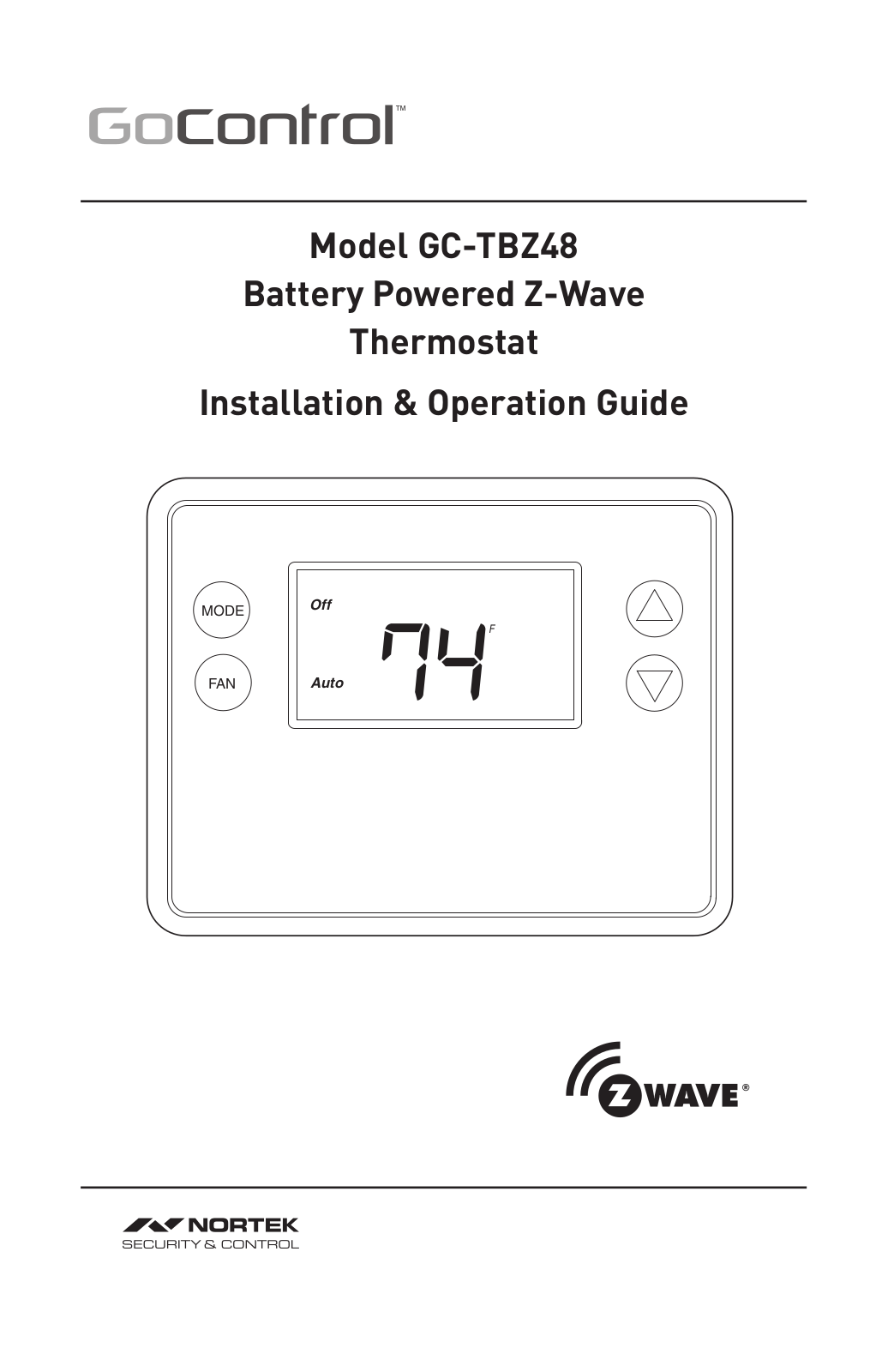
Model GC-TBZ48

Battery Powered Z-Wave

Thermostat

Installation & Operation Guide

MODE Off

FAN Auto 74F

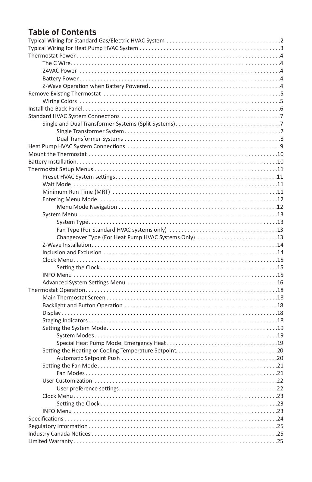
Table of Contents


Typical Wiring for Standard Gas/Electric HVAC System . . . . . . . . . . . . . . . . . . . . . . . . . . . . . . . . . . . .

. .2

Typical Wiring for Heat Pump HVAC System . . . . . . . . . . . . . . . . . . . . . . . . . . . . . . . . . . . . . . . . . . . . .

. .3

Thermostat Power .

. . . . . . . . . . .

. . . . . . . . . . . . . . . . . . . . . . . . . . . . . . . . . . . . . . . . . . . . . . . . . . . . . . .

.4

The C Wire. . . .

. . . . . . . . . .

. . . . . . . . . . . . . . . . . . . . . . . . . . . . . . . . . . . . . . . . . . . . . . . . . . . . . . .

.4

24VAC Power .

. . . . . . . . . .

. . . . . . . . . . . . . . . . . . . . . . . . . . . . . . . . . . . . . . . . . . . . . . . . . . . . . . .

.4

Ba

ery Power .

. . . . . . . . . .

. . . . . . . . . . . . . . . . . . . . . . . . . . . . . . . . . . . . . . . . . . . . . . . . . . . . . . .

.4

Z-Wave Opera on when Ba ery Powered. . . . . . . . . . . . . . . . . . . . . . . . . . . . . . . . . . . . . . . . . . .

.4

Remove Exis ng Thermostat . . .

. . . . . . . . . . . . . . . . . . . . . . . . . . . . . . . . . . . . . . . . . . . . . . . . . . . . . . .

.5

Wiring Colors .

. . . . . . . . . .

. . . . . . . . . . . . . . . . . . . . . . . . . . . . . . . . . . . . . . . . . . . . . . . . . . . . . . .

.5

Install the Back Panel. . . . . . . . . .

. . . . . . . . . . . . . . . . . . . . . . . . . . . . . . . . . . . . . . . . . . . . . . . . . . . . . . .

.6

Standard HVAC System Connec

ons . . . . . . . . . . . . . . . . . . . . . . . . . . . . . . . . . . . . . . . . . . . . . . . . . . . .

.7

Single and Dual Transformer Systems (Split Systems) . . . . . . . . . . . . . . . . . . . . . . . . . . . . . . . . . .

.7


Single Transformer System . . . . . . . . . . . . . . . . . . . . . . . . . . . . . . . . . . . . . . . . . . . . . . . . . . .

.7


Dual Transformer Systems . . . . . . . . . . . . . . . . . . . . . . . . . . . . . . . . . . . . . . . . . . . . . . . . . . .

.8

Heat Pump HVAC System Connec ons . . . . . . . . . . . . . . . . . . . . . . . . . . . . . . . . . . . . . . . . . . . . . . . . . .

.9

Mount the Thermostat . . . . . . . .

. . . . . . . . . . . . . . . . . . . . . . . . . . . . . . . . . . . . . . . . . . . . . . . . . . . . . . .

10

Ba ery Installa

on. .

. . . . . . . . . .

. . . . . . . . . . . . . . . . . . . . . . . . . . . . . . . . . . . . . . . . . . . . . . . . . . . . . . .

10

Thermostat Setup Menus . . . . . .

. . . . . . . . . . . . . . . . . . . . . . . . . . . . . . . . . . . . . . . . . . . . . . . . . . . . . . .

11

Preset HVAC System se ngs . . . . . . . . . . . . . . . . . . . . . . . . . . . . . . . . . . . . . . . . . . . . . . . . . . . . . .

11

Wait Mode . . .

. . . . . . . . . .

. . . . . . . . . . . . . . . . . . . . . . . . . . . . . . . . . . . . . . . . . . . . . . . . . . . . . . .

11

Minimum Run Time (MRT)

. . . . . . . . . . . . . . . . . . . . . . . . . . . . . . . . . . . . . . . . . . . . . . . . . . . . . . .

11

Entering Menu Mode . . . .

. . . . . . . . . . . . . . . . . . . . . . . . . . . . . . . . . . . . . . . . . . . . . . . . . . . . . . .

12


Menu Mode Naviga on . . . . . . . . . . . . . . . . . . . . . . . . . . . . . . . . . . . . . . . . . . . . . . . . . . . . .

12

System Menu .

. . . . . . . . . .

. . . . . . . . . . . . . . . . . . . . . . . . . . . . . . . . . . . . . . . . . . . . . . . . . . . . . . .

13


System Type. . . . . . . .

. . . . . . . . . . . . . . . . . . . . . . . . . . . . . . . . . . . . . . . . . . . . . . . . . . . . . . .

13


Fan Type (For Standard HVAC systems only) . . . . . . . . . . . . . . . . . . . . . . . . . . . . . . . . . . . .

13


Changeover Type (For Heat Pump HVAC Systems Only) . . . . . . . . . . . . . . . . . . . . . . . . . . .

13

Z-Wave Installa on. . . . . . .

. . . . . . . . . . . . . . . . . . . . . . . . . . . . . . . . . . . . . . . . . . . . . . . . . . . . . . .

14

Inclusion and Exclusion . . .

. . . . . . . . . . . . . . . . . . . . . . . . . . . . . . . . . . . . . . . . . . . . . . . . . . . . . . .

14

Clock Menu . . .

. . . . . . . . . .

. . . . . . . . . . . . . . . . . . . . . . . . . . . . . . . . . . . . . . . . . . . . . . . . . . . . . . .

15


Se

ng the Clock . . . .

. . . . . . . . . . . . . . . . . . . . . . . . . . . . . . . . . . . . . . . . . . . . . . . . . . . . . . .

15

INFO Menu . . .

. . . . . . . . . .

. . . . . . . . . . . . . . . . . . . . . . . . . . . . . . . . . . . . . . . . . . . . . . . . . . . . . . .

15

Advanced System Se ngs Menu . . . . . . . . . . . . . . . . . . . . . . . . . . . . . . . . . . . . . . . . . . . . . . . . . .

16

Thermostat Opera on. . . . . . . . .

. . . . . . . . . . . . . . . . . . . . . . . . . . . . . . . . . . . . . . . . . . . . . . . . . . . . . . .

18

Main Thermostat Screen . .

. . . . . . . . . . . . . . . . . . . . . . . . . . . . . . . . . . . . . . . . . . . . . . . . . . . . . . .

18

Backlight and Bu on Opera on . . . . . . . . . . . . . . . . . . . . . . . . . . . . . . . . . . . . . . . . . . . . . . . . . . .

18

Display . .

. . . . .

. . . . . . . . . .

. . . . . . . . . . . . . . . . . . . . . . . . . . . . . . . . . . . . . . . . . . . . . . . . . . . . . . .

18

Staging Indicators . . . . . . . .

. . . . . . . . . . . . . . . . . . . . . . . . . . . . . . . . . . . . . . . . . . . . . . . . . . . . . . .

18

Se

ng the System Mode. .

. . . . . . . . . . . . . . . . . . . . . . . . . . . . . . . . . . . . . . . . . . . . . . . . . . . . . . .

19


System Modes . . . . . .

. . . . . . . . . . . . . . . . . . . . . . . . . . . . . . . . . . . . . . . . . . . . . . . . . . . . . . .

19


Special Heat Pump Mode: Emergency Heat . . . . . . . . . . . . . . . . . . . . . . . . . . . . . . . . . . . . .

19

Se

ng the Hea ng or Cooling Temperature Setpoint. . . . . . . . . . . . . . . . . . . . . . . . . . . . . . . . . .

20


Automa

c Setpoint Push . . . . . . . . . . . . . . . . . . . . . . . . . . . . . . . . . . . . . . . . . . . . . . . . . . . .

20

Se

ng the Fan Mode. . . . .

. . . . . . . . . . . . . . . . . . . . . . . . . . . . . . . . . . . . . . . . . . . . . . . . . . . . . . .

21


Fan Modes . . . . . . . . .

. . . . . . . . . . . . . . . . . . . . . . . . . . . . . . . . . . . . . . . . . . . . . . . . . . . . . . .

21

User Customiza on . . . . . .

. . . . . . . . . . . . . . . . . . . . . . . . . . . . . . . . . . . . . . . . . . . . . . . . . . . . . . .

22


User preference se

ngs. . . . . . . . . . . . . . . . . . . . . . . . . . . . . . . . . . . . . . . . . . . . . . . . . . . . .

22

Clock Menu . . .

. . . . . . . . . .

. . . . . . . . . . . . . . . . . . . . . . . . . . . . . . . . . . . . . . . . . . . . . . . . . . . . . . .

23


Se

ng the Clock . . . .

. . . . . . . . . . . . . . . . . . . . . . . . . . . . . . . . . . . . . . . . . . . . . . . . . . . . . . .

23

INFO Menu . . .

. . . . . . . . . .

. . . . . . . . . . . . . . . . . . . . . . . . . . . . . . . . . . . . . . . . . . . . . . . . . . . . . . .

23

Specifica

ons .

. . . . .

. . . . . . . . . .

. . . . . . . . . . . . . . . . . . . . . . . . . . . . . . . . . . . . . . . . . . . . . . . . . . . . . . .

24

Regulatory Informa

on . . . . . . . .

. . . . . . . . . . . . . . . . . . . . . . . . . . . . . . . . . . . . . . . . . . . . . . . . . . . . . . .

25

Industry Canada No

ces . . . . . . .

. . . . . . . . . . . . . . . . . . . . . . . . . . . . . . . . . . . . . . . . . . . . . . . . . . . . . . .

25

Limited Warranty . . .

. . . . . . . . . .

. . . . . . . . . . . . . . . . . . . . . . . . . . . . . . . . . . . . . . . . . . . . . . . . . . . . . . .

25

GC-TBZ48

BATTERY POWERED Z-WAVE THERMOSTAT

INSTALLATION INSTRUCTIONS

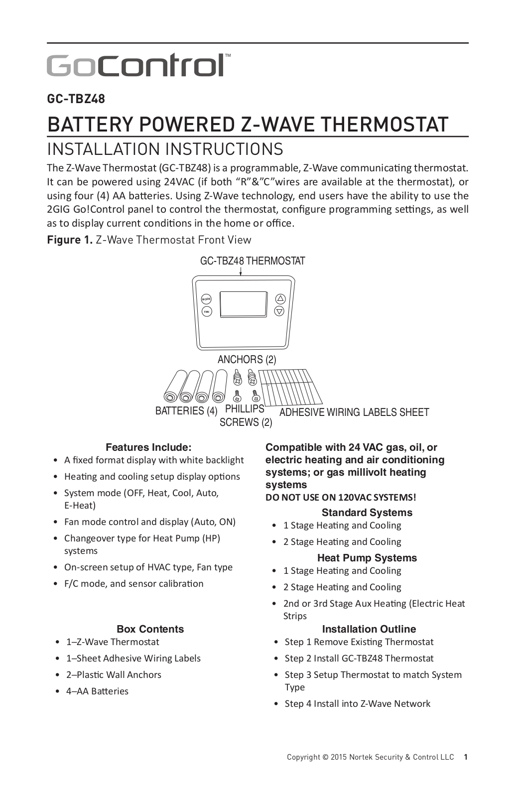
The Z-Wave Thermostat (GC-TBZ48) is a programmable, Z-Wave communica ng thermostat. It can be powered using 24VAC (if both “R”&”C”wires are available at the thermostat), or using four (4) AA ba eries. Using Z-Wave technology, end users have the ability to use the 2GIG Go!Control panel to control the thermostat, configure programming se ngs, as well as to display current condi ons in the home or o ce.

Figure 1. Z-Wave Thermostat Front View

GC-TBZ48 THERMOSTAT

MODE

FAN

ANCHORS (2)

Y

BATTERIES (4) PHILLIPS ADHESIVE WIRING LABELS SHEET

SCREWS (2)

Features Include:

• A fixed format display with white backlight

• Hea ng and cooling setup display op ons

System mode (OFF, Heat, Cool, Auto, E-Heat)

Fan mode control and display (Auto, ON)

Changeover type for Heat Pump (HP) systems

On-screen setup of HVAC type, Fan type

F/C mode, and sensor calibra on

Compatible with 24 VAC gas, oil, or electric heating and air conditioning systems; or gas millivolt heating systems

DO NOT USE ON 120VAC SYSTEMS!

Standard Systems

1 Stage Hea ng and Cooling

2 Stage Hea ng and Cooling

Heat Pump Systems

1 Stage Hea ng and Cooling

2 Stage Hea ng and Cooling

2nd or 3rd Stage Aux Hea ng (Electric Heat Strips


Box Contents

Installation Outline

1─Z-Wave Thermostat

• Step 1 Remove Exis ng Thermostat

• 1─Sheet Adhesive Wiring Labels

• Step 2 Install GC-TBZ48 Thermostat

2─Plas c Wall Anchors

• Step 3 Setup Thermostat to match System

4─AA Ba eries

Type


• Step 4 Install into Z-Wave Network

Copyright © 2015 Nortek Security & Control LLC 1

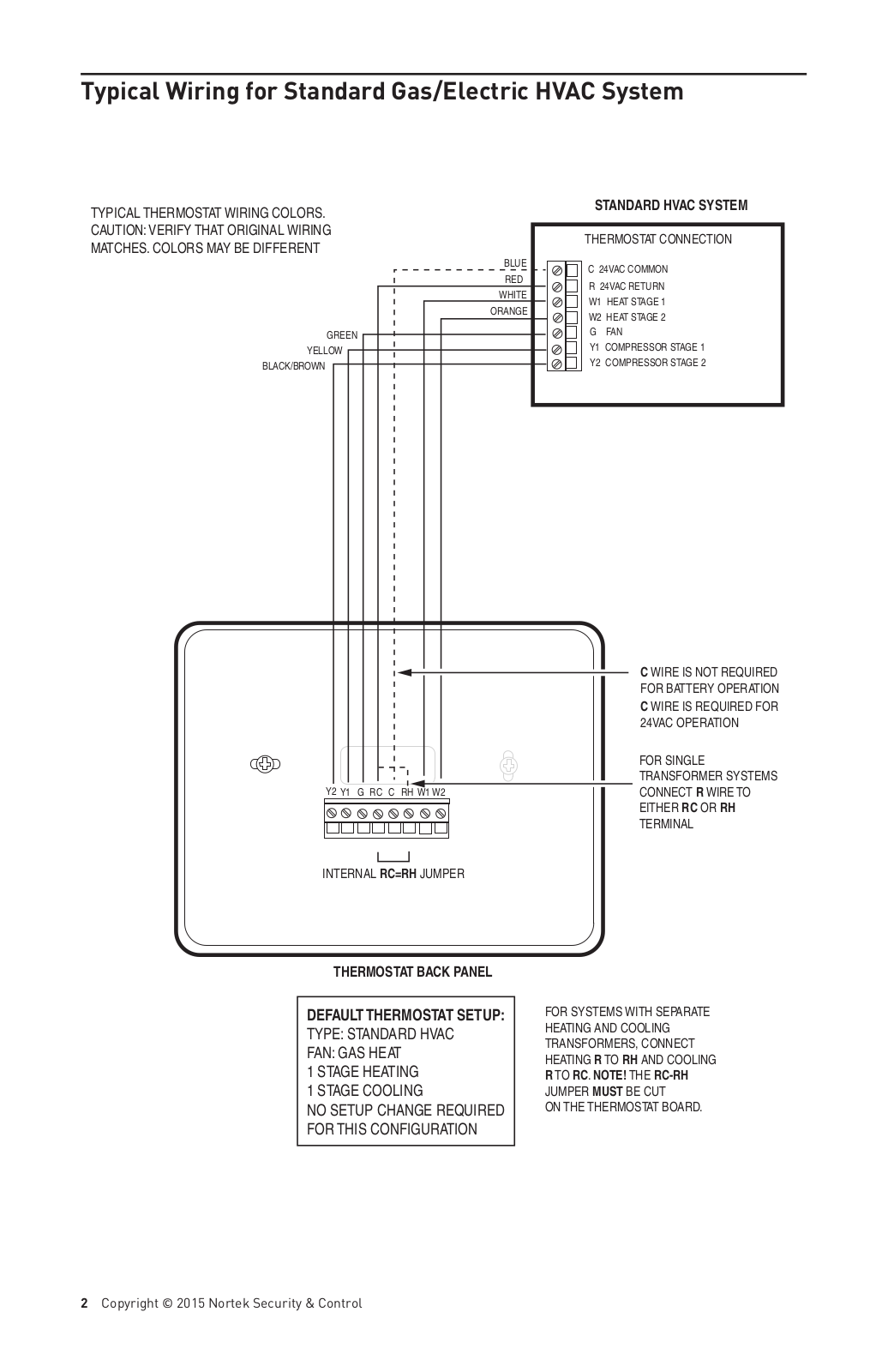
Typical Wiring for Standard Gas/Electric HVAC System

TYPICAL THERMOSTAT WIRING COLORS.

STANDARD HVAC SYSTEM


CAUTION: VERIFY THAT ORIGINAL WIRING

THERMOSTAT CONNECTION

MATCHES. COLORS MAY BE DIFFERENT


BLUE

C 24VAC COMMON


RED


R 24VAC RETURN


WHITE


W1 HEAT STAGE 1


ORANGE


W2 HEAT STAGE 2


GREEN


G FAN


Y1 COMPRESSOR STAGE 1

YELLOW


Y2 COMPRESSOR STAGE 2

BLACK/BROWN


C WIRE IS NOT REQUIRED


FOR BATTERY OPERATION


C WIRE IS REQUIRED FOR


24VAC OPERATION


FOR SINGLE


TRANSFORMER SYSTEMS

Y2 Y1 G RC C RH W1 W2


CONNECT R WIRE TO


EITHER RC OR RH


TERMINAL

INTERNAL RC=RH JUMPER


THERMOSTAT BACK PANEL

DEFAULT THERMOSTAT SETUP:

TYPE: STANDARD HVAC FAN: GAS HEAT

1 STAGE HEATING

1 STAGE COOLING

NO SETUP CHANGE REQUIRED FOR THIS CONFIGURATION

FOR SYSTEMS WITH SEPARATE HEATING AND COOLING TRANSFORMERS, CONNECT HEATING R TO RH AND COOLING

R TO RC. NOTE! THE RC-RH

JUMPER MUST BE CUT

ON THE THERMOSTAT BOARD.

2 Copyright © 2015 Nortek Security & Control

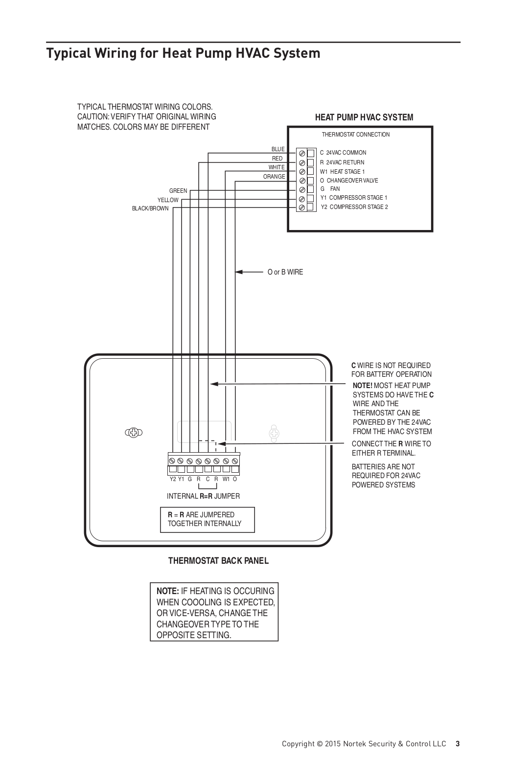
Typical Wiring for Heat Pump HVAC System

TYPICAL THERMOSTAT WIRING COLORS.


CAUTION: VERIFY THAT ORIGINAL WIRING


HEAT PUMP HVAC SYSTEM

MATCHES. COLORS MAY BE DIFFERENT


THERMOSTAT CONNECTION


BLUE

C 24VAC COMMON


RED


R 24VAC RETURN


WHITE


W1 HEAT STAGE 1


ORANGE


O CHANGEOVER VALVE


GREEN


G FAN


Y1 COMPRESSOR STAGE 1

YELLOW


Y2 COMPRESSOR STAGE 2

BLACK/BROWN


O or B WIRE

Y2 Y1 G R

C R

W1 O

INTERNAL R=R JUMPER

R = R ARE JUMPERED

TOGETHER INTERNALLY

THERMOSTAT BACK PANEL

NOTE: IF HEATING IS OCCURING WHEN COOOLING IS EXPECTED, OR VICE-VERSA, CHANGE THE CHANGEOVER TYPE TO THE OPPOSITE SETTING.

C WIRE IS NOT REQUIRED FOR BATTERY OPERATION

NOTE! MOST HEAT PUMP SYSTEMS DO HAVE THE C WIRE AND THE THERMOSTAT CAN BE POWERED BY THE 24VAC FROM THE HVAC SYSTEM

CONNECT THE R WIRE TO EITHER R TERMINAL.

BATTERIES ARE NOT REQUIRED FOR 24VAC POWERED SYSTEMS

Copyright © 2015 Nortek Security & Control LLC 3

Thermostat Power

The thermostat can be powered by either 24VAC from the HVAC system or from four (4) type AA internal ba eries. DO NOT use this thermostat for line voltage controls (120/240VAC).

The C Wire

If the 24VAC common wire (usually blue) is present and is connected to 24VAC common at the HVAC system end, the thermostat can be powered from the HVAC system and ba eries are not required. If there is no common wire, ba eries are required.

24VAC Power

Powering the thermostat with 24VAC power requires both the 24VAC “C” common wire (typically a blue wire) and the 24VAC ”R” return wire (typically a red wire).

BaƩery Power

Powering the thermostat from ba eries does not require a “C” wire connec on.

DO NOT install ba eries if the thermostat is powered by 24VAC. They are not required for backup.

If the thermostat is powered by ba eries, the thermostat will operate for approximately (2) two years on four (4) AA Alkaline ba eries depending on the frequency of user opera ons and backlight opera on. Always use Alkaline ba eries and replace in complete sets of four (4) at a me.

Z-Wave OperaƟon when BaƩery Powered

IMPORTANT: If the thermostat is installed on a Z-Wave network, while it is baƩery powered, it will NOT work as a Z-Wave repeater.

CAUTION: Do not install ba eries and temporarily power the thermostat from 24VAC to include onto a Z-Wave network. Shortened ba ery life may occur when 24VAC power is removed.

4 Copyright © 2015 Nortek Security & Control

Remove Existing Thermostat

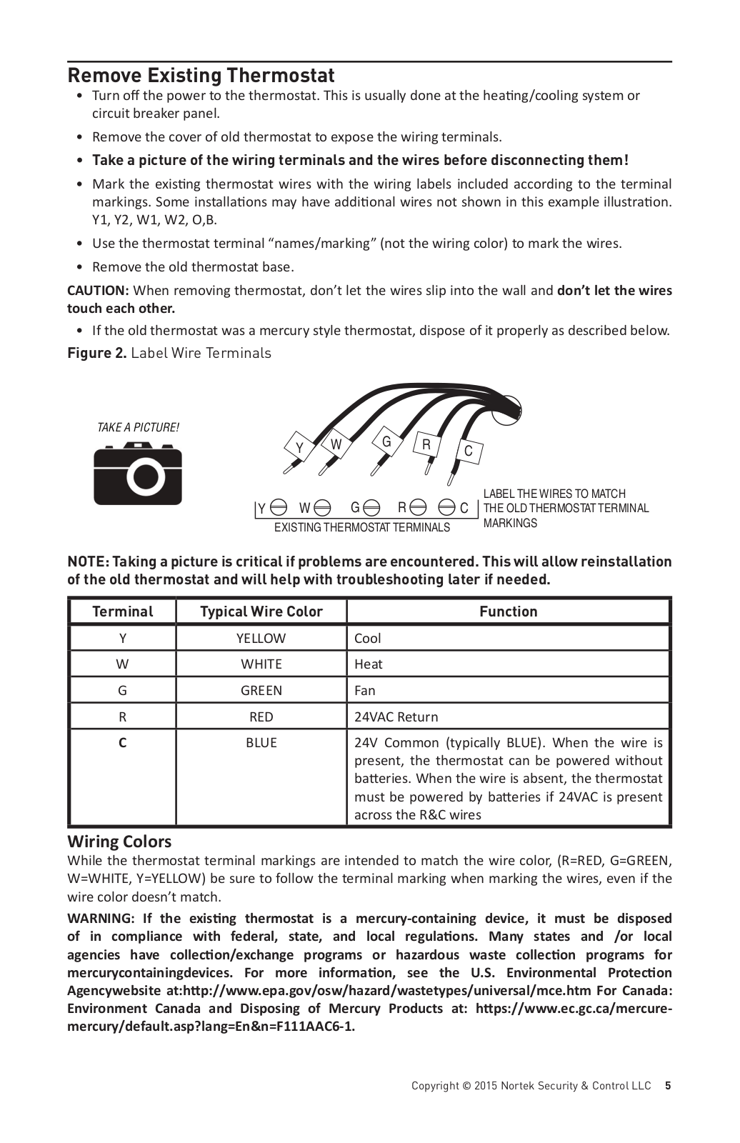
Turn o the power to the thermostat. This is usually done at the hea ng/cooling system or circuit breaker panel.

Remove the cover of old thermostat to expose the wiring terminals.

Take a picture of the wiring terminals and the wires before disconnecting them!

Mark the exis ng thermostat wires with the wiring labels included according to the terminal markings. Some installa ons may have addi onal wires not shown in this example illustra on. Y1, Y2, W1, W2, O,B.

Use the thermostat terminal “names/marking” (not the wiring color) to mark the wires.

Remove the old thermostat base.

CAUTION: When removing thermostat, don’t let the wires slip into the wall and don’t let the wires touch each other.

• If the old thermostat was a mercury style thermostat, dispose of it properly as described below.

Figure 2. Label Wire Terminals

TAKE A PICTURE!

Y W G R C

Y W G R C

EXISTING THERMOSTAT TERMINALS

LABEL THE WIRES TO MATCH THE OLD THERMOSTAT TERMINAL MARKINGS

NOTE: Taking a picture is critical if problems are encountered. This will allow reinstallation of the old thermostat and will help with troubleshooting later if needed.

Terminal

Typical Wire Color

Function


Y

YELLOW

Cool


W

WHITE

Heat

G

GREEN

Fan


R

RED

24VAC Return


C

BLUE

24V Common (typically BLUE). When the wire is


present, the thermostat can be powered without


ba eries. When the wire is absent, the thermostat


must be powered by ba eries if 24VAC is present


across the R&C wires

Wiring Colors

While the thermostat terminal markings are intended to match the wire color, (R=RED, G=GREEN, W=WHITE, Y=YELLOW) be sure to follow the terminal marking when marking the wires, even if the wire color doesn’t match.

WARNING: If the exisƟng thermostat is a mercury-containing device, it must be disposed of in compliance with federal, state, and local regulaƟons. Many states and /or local agencies have collecƟon/exchange programs or hazardous waste collecƟon programs for mercurycontainingdevices. For more informaƟon, see the U.S. Environmental ProtecƟon Agencywebsite at:hƩp://www.epa.gov/osw/hazard/wastetypes/universal/mce.htm For Canada: Environment Canada and Disposing of Mercury Products at: hƩps://www.ec.gc.ca/mercure- mercury/default.asp?lang=En&n=F111AAC6-1.

Copyright © 2015 Nortek Security & Control LLC 5

Linear GC-TBZ48 User Manual

Install the Back Panel

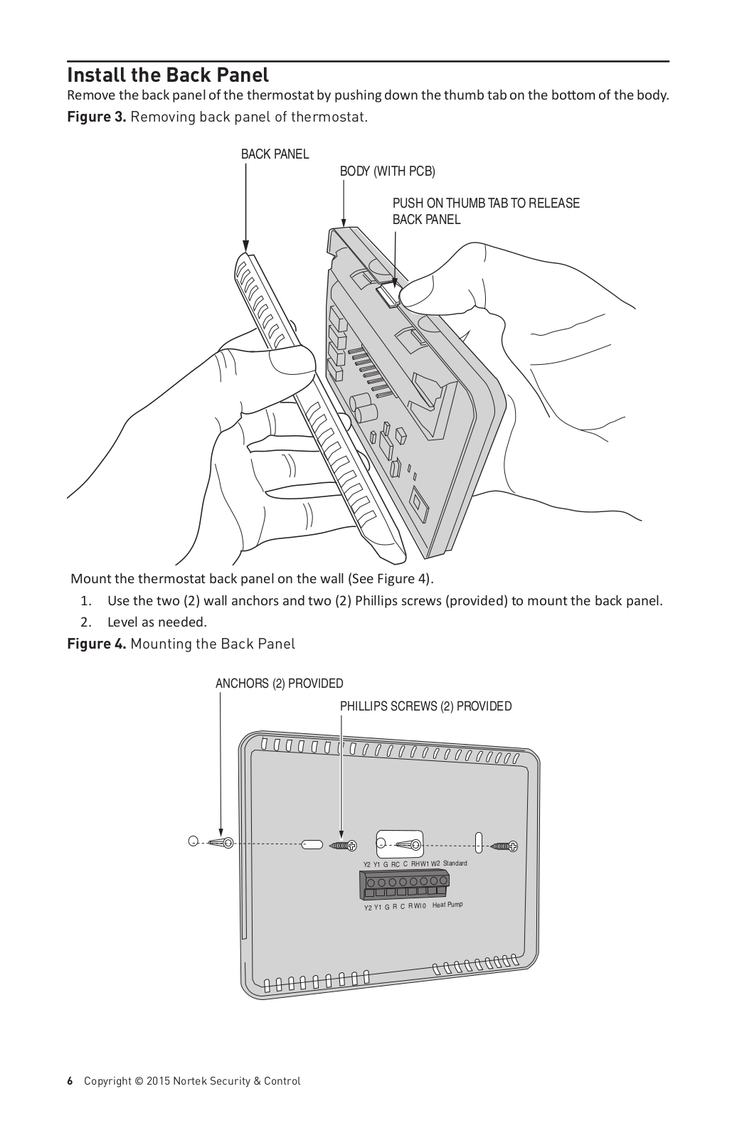
Remove the back panel of the thermostat by pushing down the thumb tab on the bo om of the body.

Figure 3. Removing back panel of thermostat.

BACK PANEL

BODY (WITH PCB)

PUSH ON THUMB TAB TO RELEASE

BACK PANEL

Mount the thermostat back panel on the wall (See Figure 4).

1.Use the two (2) wall anchors and two (2) Phillips screws (provided) to mount the back panel.

2.Level as needed.

Figure 4. Mounting the Back Panel

ANCHORS (2) PROVIDED

PHILLIPS SCREWS (2) PROVIDED

Y2 Y1 G RC C RH W1 W2 Standard

Y2 Y1 G R C R WI 0

Heat

Pump


6 Copyright © 2015 Nortek Security & Control

Standard HVAC System Connections

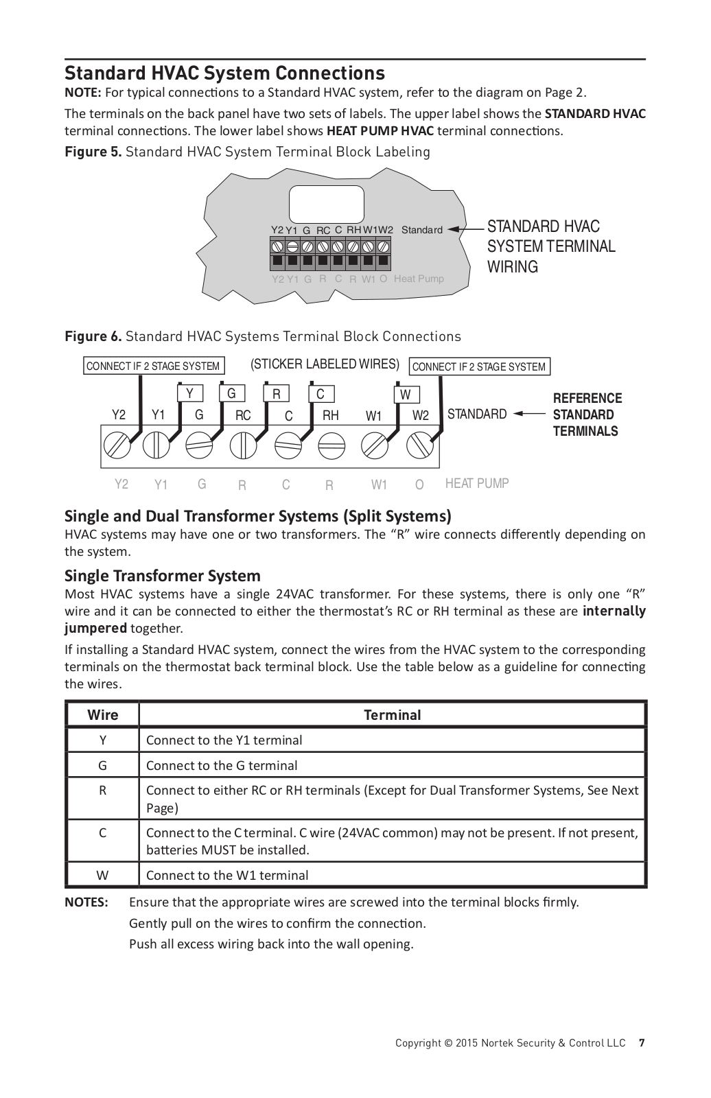
NOTE: For typical connec ons to a Standard HVAC system, refer to the diagram on Page 2.

The terminals on the back panel have two sets of labels. The upper label shows the STANDARD HVAC terminal connec ons. The lower label shows HEAT PUMP HVAC terminal connec ons.

Figure 5. Standard HVAC System Terminal Block Labeling


Y2 Y1 G RC C RH W1W2

Standard

STANDARD HVAC


SYSTEM TERMINAL


Y2 Y1 G

R C

R W1 O Heat Pump

WIRING


Figure 6. Standard HVAC Systems Terminal Block Connections


CONNECT IF 2 STAGE SYSTEM

(STICKER LABELED WIRES)

CONNECT IF 2 STAGE SYSTEM


Y

G

R

C


W


REFERENCE

Y2

Y1

G

RC

C

RH

W1

W2

STANDARD

STANDARD


TERMINALS

Y2

Y1

G

R

C

R

W1

O

HEAT PUMP


Single and Dual Transformer Systems (Split Systems)

HVAC systems may have one or two transformers. The “R” wire connects di erently depending on the system.

Single Transformer System

Most HVAC systems have a single 24VAC transformer. For these systems, there is only one “R” wire and it can be connected to either the thermostat’s RC or RH terminal as these are internally jumpered together.

If installing a Standard HVAC system, connect the wires from the HVAC system to the corresponding terminals on the thermostat back terminal block. Use the table below as a guideline for connec ng the wires.

Wire

Terminal


Y

Connect to the Y1 terminal

G

Connect to the G terminal


R

Connect to either RC or RH terminals (Except for Dual Transformer Systems, See Next


Page)

C

Connect to the C terminal. C wire (24VAC common) may not be present. If not present,


ba eries MUST be installed.

W

Connect to the W1 terminal

NOTES: Ensure that the appropriate wires are screwed into the terminal blocks firmly. Gently pull on the wires to confirm the connec on.

Push all excess wiring back into the wall opening.

Copyright © 2015 Nortek Security & Control LLC 7

Loading...
+ 19 hidden pages