

Page 1
Wireless Microphone
Technology Guide
Page 2

Electronic version available at http://line6.com/xd-v.
www.line6.com
© 2010 Line 6, Inc.
Version 1.3
All rights reserved
Reproduction in whole or part
without written permission is prohibited
Page 3

What’s Inside
Introduction ....................................................................................................................................................... 4
The Basics ......................................................................................................................................................... 5
What is RF? ................................................................................................................................................... 5
RF Transmission ............................................................................................................................................ 5
RF Reception ................................................................................................................................................. 5
Radio Operation ................................................................................................................................................. 5
Choosing a Frequency ..................................................................................................................................5
Radio Interference ......................................................................................................................................... 7
Radio Distance .............................................................................................................................................. 8
Diversity ......................................................................................................................................................... 8
Choosing a Channel ...................................................................................................................................... 9
Audio Transmission ......................................................................................................................................... 9
Dynamic Range ............................................................................................................................................. 9
Distortion ......................................................................................................................................................11
Frequency Response ...................................................................................................................................11
Summary ......................................................................................................................................................... 11
Digital Benefits ..............................................................................................................................................11
Line 6, Inc. | Wireless Microphone Technology Guide
3
Page 4
Introduction
Wireless microphones provide singers, performers, and presenters with
the freedom of mobility unconstrained by cables. But this benefit has
historically been provided at the cost of compromised audio quality, radio
interference artifacts, and setup complexity. For over fifty years analog
FM radio technology has been the dominant approach utilized for wireless
microphones, but now digital wireless promises to usher in an era of
uncompromised, problem-free performance.
This paper’s goal is to provide a technical background of both traditional
analog wireless and digital wireless technology, and to provide insight into
the differences between them.
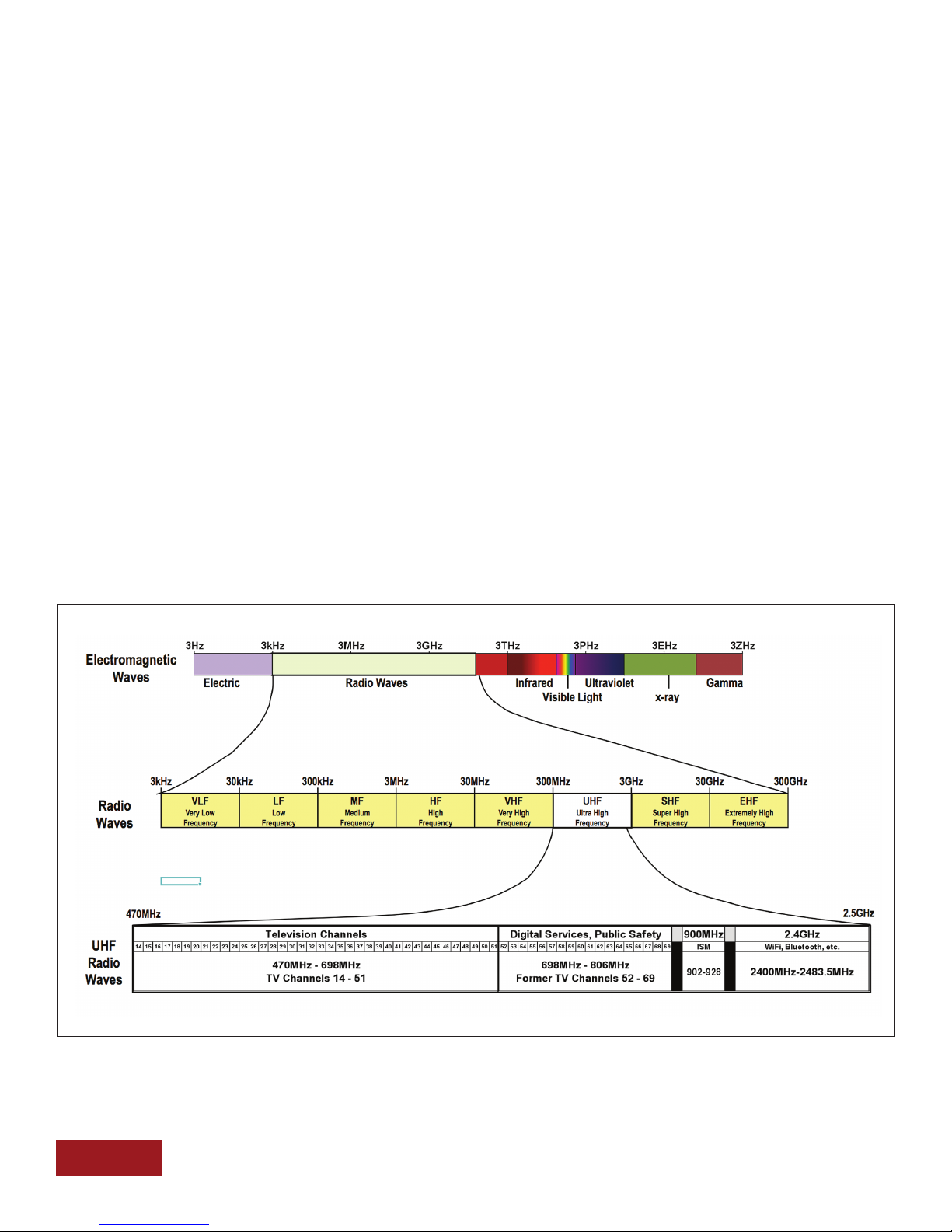
Figure 1 Radio waves range from 3 kHz to 300GHz in the Electromagnetic Spectrum.
Professional wireless microphones operate in the UHF range of radio waves.
4
Line 6, Inc. | Wireless Microphone Technology Guide
Page 5
The Basics
What is RF?
RF is an abbreviation for “Radio Frequency” and
is used to describe the range of spectrum utilized
for many types off wireless transmissions, including radio,
television, mobile phones, remote controls, and wireless
microphones. The term “Radio” in its most basic
definition is the transmission of electromagnetic waves
through space. These electromagnetic waves can vary
in length and amplitude and occur naturally all around
us. The wavelength is the physical distance between
the start of one cycle and the start off the next cycle as
the wave moves through space. The rate of the wave is
measured in Hertz (abbreviated Hz), or cycles per second. This is called the “Frequency” of the electromagnetic
wave. Figure 1 shows a basic guide of electromagnetic
waves and their respective frequencies, with radio waves
broken out into the lower part of the figure.
“zeroes”) is a form of frequency modulation called
Frequency Shift Keying (FSK). The frequency of the
carrier is shifted to represent a bit of data, as shown in
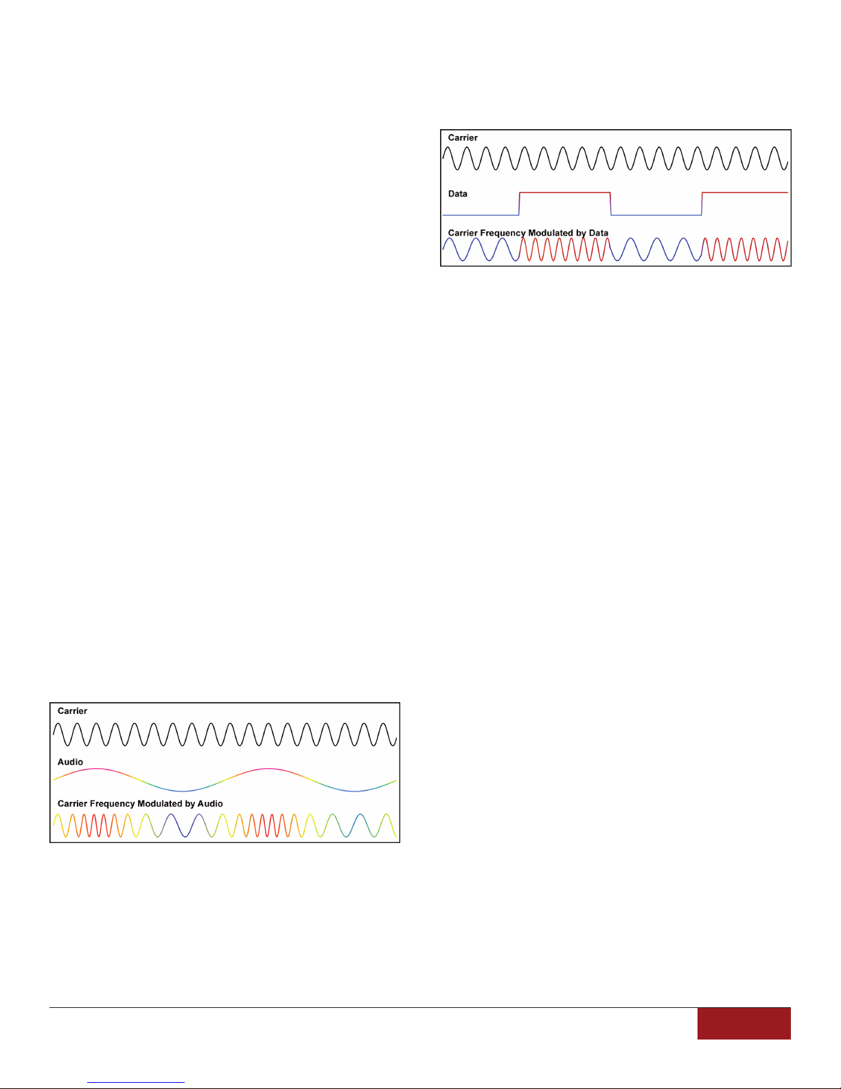
Figure 3.
Figure 3 FSK of a radio wave by a data signal
Additional types of modulation of frequency and
phase of a carrier can enable several bits of data to be
transmitted within one portion of the carrier, allowing for
more efficient transfer of data over the air.
RF Reception
RF Transmission
Radio waves can be used as a method for
transmitting information. The most common method
used for transmitting analog audio via RF is with
Frequency Modulation, or FM. The radio frequency
being transmitted is called a carrier wave. This carrier’s
frequency is modulated up and down depending on the
amplitude of the audio. This technique is used in FM
broadcast radio, and in analog wireless microphones.
Figure 2 gives a visual representation of a carrier wave
modulated by an audio wave.
Figure 2 FM of a radio wave by an audio signal
(proportions scaled for graphic clarity
For the transmission of digital audio, a number of
different techniques exist, but they share in the principle
that the carrier’s frequency (and sometimes phase) is
altered based on the data to be transmitted. A common
example of transmitting digital signal (“ones”” and
In order to recover the audio or data signal from the
carrier, the receiver needs to demodulate the frequency
modulation of the carrier. A number of different techniques
exist for performing this function. The details of this
process will not be covered in this paper, but can be explored further in other RF technology literature if desired.
Radio Operation
Choosing a Frequency
In the US, radio frequency usage is governed by the
Federal Communications Commission. Similar agencies
regulate communications in most other countries.
The FCC designates what frequencies can be used
by whom, as well as how much power (in Watts) can be
broadcast.
Television is broadcast using radio waves with typically
hundreds of thousands of Watts of power.
Wireless microphones, WiFi hubs, and other portable
wireless devices typically transmit with less than one Watt
of power.
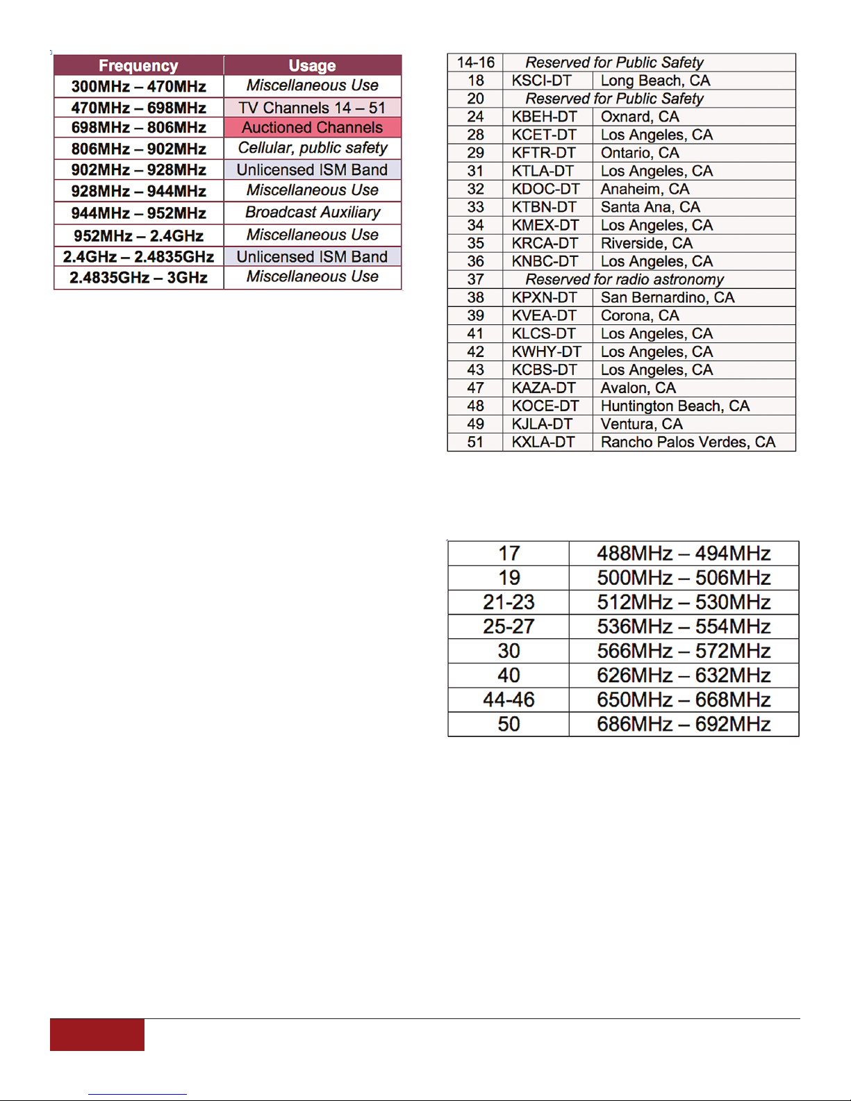
In the UHF radio spectrum, the allocation of frequencies
is shown in the following table:
Line 6, Inc. | Wireless Microphone Technology Guide
5
Page 6
UHF analog wireless microphones typically operate
in the broadcast TV range designated as channels 14
through 51 (in the USA). Many devices also exist that
operate in the band that previously occupied TV channels
52 through 69 (also known as the “700MHz band”), but as
of 2009 these frequencies were auctioned for commercial
use and public safety, and can no longer be used
for wireless microphones.
Some analog wireless systems have been designed to
operate in either of the two ISM bands (named for their
general usage in Industrial, Scientific, and Medical
applications, although not limited to these areas).
However, for analog wireless to operate with minimal
problems, it needs to occupy an unused frequency band.
This makes the ISM bands problematic, since other
usage might interfere with their operation. (This is not a
problem for digital data, which will be described later.)
The TV bands are used for digital broadcast
television, which can overwhelm the power of a wireless
microphone’s signal. But since not every broadcast
channel is currently used in every city, there are
potentially open areas available, commonly referred to as
“white spaces”. This term comes from the “white” screen
of “snow” (noise) that would appear on a TV if it was
tuned to an unused channel.
For a wireless microphone to function in the TV bands,
a white space frequency must be selected. This varies
from city to city, depending on which TV channels are
in use. For example, here are the channels used in Los
Angeles:
This leaves the following channels and frequency
ranges currently available:
According to FCC records however, all of these
remaining channels have applications pending for new
TV stations.
Typical analog wireless systems have selectable
channels, but cover only a part of the UHF range (usually
from 18MHz to 60MHz wide). Each city has its own UHF
channel usage assignment, so it is important to be
familiar with what channels are available prior to
purchasing an analog wireless system to be sure its
range is assignable to an unused TV channel. For
example, a wireless system with a tunable range of
572MHz to 590MHz (channels 31 through 33) would
not be suitable for use in Los Angeles.
6
Line 6, Inc. | Wireless Microphone Technology Guide
Page 7

Until now, the FCC has always required a license to
use wireless microphones within any of the UHF TV
channels, as described in Part 74 Subpart H of Title 47
of the Code of Federal Regulations.
the same time. Or when manually tuning a radio to a
frequency that is not broadcasting, noise can be heard
as a result of the spurious electromagnetic waves that
are always around us.
For the time being the FCC is allowing wireless
microphones to be used without a license under part
15 rules that restrict power levels and require them
not to interfere with licensed users as well as accept
interference from those licensed users of the band.
The rules are expected to be revised after June 2010.
Beginning in 2010, new TV Band Devices (TVBDs,
previously called White Space Devices,, or WSDs) are
expected to enter the market and take advantage of a
recent FCC ruling allowing unlicensed use of white space
spectrum not assigned to TV broadcast in that area. It is
expected that TVBDs will provide services like extended
WiFi and in-home wireless video. These devices are
required to monitor the radio waves once per minute to
detect if a wireless microphone is present and to avoid
that frequency if detected, although it is not yet clear how
effective this technique will be in limiting interference with
analog wireless microphones.
Line 6 digital wireless microphone systems operate
in ISM bands. These bands do not require a license,
and are free from high powered interference such as
broadcast TV.
As a result they are also free of geographical
restrictions and can operate on all channels worldwide
without the need to determine what commercial
broadcast TV channels are operating nearby.
They do, however, have to coexist with other users
of these bands. In the 900MMHz range, this typically
includes some cordless telephones and other low power
remote applications. The 2.4GHz range also includes
WiFi and Bluetooth communication. But since all of these
devices are transmitting data as opposed to analog
audio, the spectrum can be effectively shared with
multiple devices. Unlike analog transmission, digital
data is coded for the specific recipient of that data and
all other data is ignored. This also applies to WiFi
communication, which can support dozens of computers
all in the same room without worry that one will receive
information intended for another.
In analog wireless microphones, any interference
that causes audio artifacts can disrupt a performance.
Causes of interference include obstructions (people,
walls, equipment), radio wave reflections (causing multiple paths of the signal to be received), and TV channels.
Any interference that alters the reception off the audio
modulation of the carrier can produce unwanted audio
artifacts. One way that analog wireless attempts to
reduce spurious radio waves from being turned into
audio is the use off a pilot tone and a squelch circuit.
The squelch circuit’s main purpose is to mute
(“squelch”) the audio output when the transmitter’s
signal is not being received. Without this, the receiver
would output high amplitude noise due to the random
radio waves it is receiving. But when the transmitter
signal is being received, the system needs some method
to attempt to differentiate the wanted signal from any
interfering signal. One method is to have the transmitter
always transmit a pilot tone along with the audio. This
tone is usually at a very high audio frequency, and is
filtered out before the audio is output from the receiver.
If the receiver does not see the pilot tone at the expected
level, then the squelch circuit is turned on to mute the
audio. Since modulated tones can be created due to
interference, spurious audio is still able to pass through
the system in certain circumstances.
Digital wireless microphones, like all digital
transmission systems, rely on data being “correct”,
that is, a zero is always a zero, and a one is always a
one. However, noise or interference on the signal will
not have an impact on the receiver’s interpretation of
the data unless it is significant enough to make the data
unreadable.
When an analog audio signal has noise or
interference, the result becomes audible because
it is combined with the intended audio waveform,
as shown here:
Radio Interference
Anyone familiar with a traditional FM radio has
experienced many types of interference artifacts. When
two radio stations are close together in frequency, it is
sometimes possible to hear a combination of both at
Line 6, Inc. | Wireless Microphone Technology Guide
7
Page 8
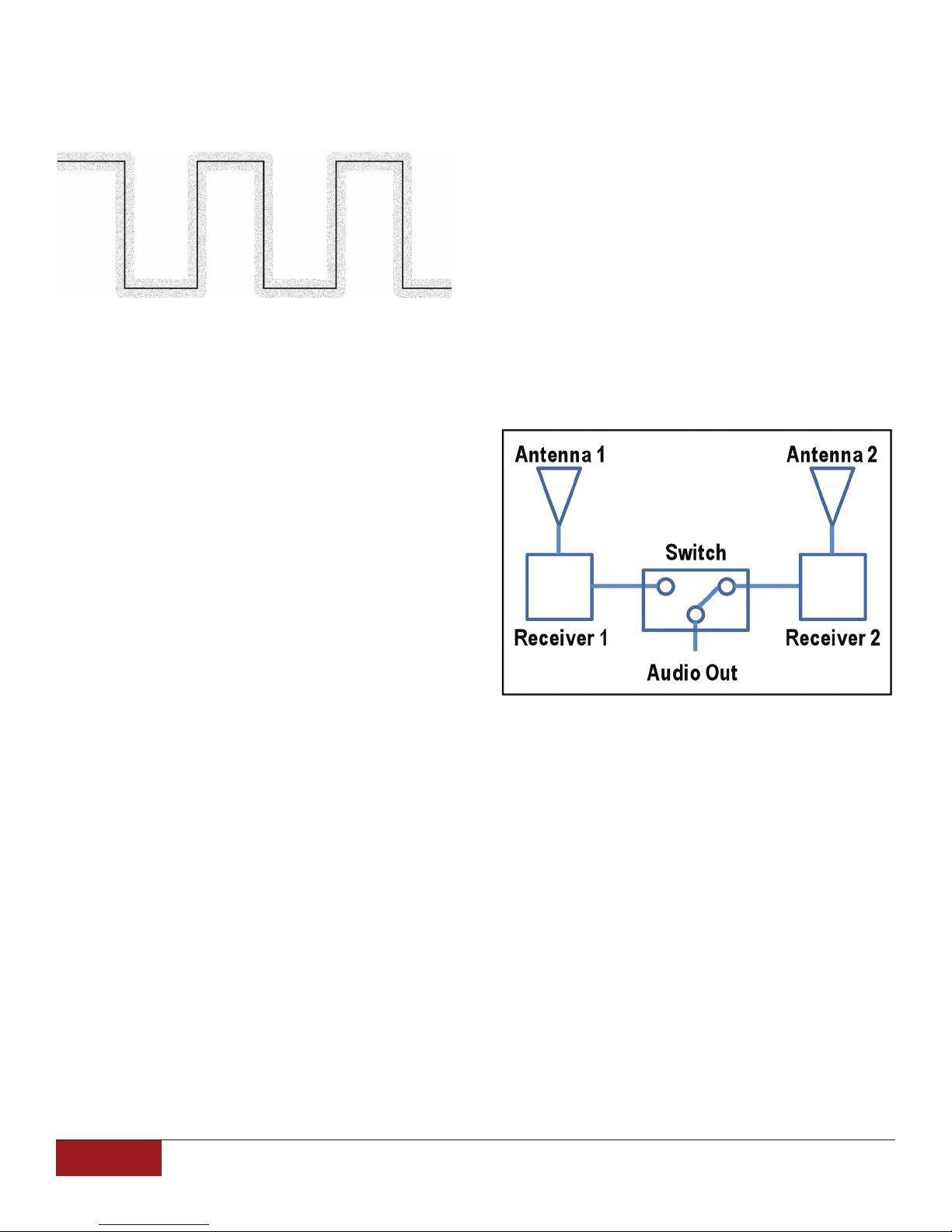
When a digital signal has noise or interference
up to a certain level, the data can still be properly
interpreted as ones and zeroes without any alteration
in the audio, as shown in the next diagram:
The low and high signals (zeroes and ones) can still be
read without any audible artifacts.
Significant radio interference can impact a digital
receiver’s ability to correctly interpret the zeroes
and ones. But digital has the advantage of being able to
include additional information to help the receiver know
if the data is correct. This is called error detection, and is
commonly used in most digital storage or communication
systems. This is usually performed by adding additional
data to each packet of information that can be
mathematically checked to validate the whole packet
of data as being good or bad.
In digital wireless systems, the audio quality remains
constant throughout the distance range, since the level
of noise on the digital signal does not affect the analog
audio signal.
Diversity
The term “true diversity” is often used too describe
a feature of many analog wireless systems that utilize
two antennas and two receiver circuits. Since the two
antennas are spaced apart, they pick up the RF signal
relative to their respective location. When the signal at
one antenna is weak (due to an obstruction or multipath
interference), the signal at the other antenna may not be
as affected. These wireless systems have circuitry that
selects the audio signal from the receiver that has the
stronger signal. Switching noise is encountered,
but is usually low enough to not be disruptive.
For a simple example, if the numbers 3 and 5 were to
be transmitted, and along with them their sum (8) was
also transmitted, the receiver could check that the two
numbers received add up to the third number to be sure
that the data was received correctly. If the numbers don’t
add up, then error correction or concealment can be
deployed (these techniques won’t be discussed here,
but use additional transmitted data to reconstruct any
data that is lost).
These types of techniques are used on CDs and DVDs,
and explain why a disk can have a significant scratch and
still be playable without errors. Additionally, digital systems
can encode their data so that other digital signals in the
same band cannot be misinterpreted as the intended data.
The only data that will be read is the data intended for that
receiver.
Radio Distance
The further away a transmitter is from its receiver, the
lower in level the transmitter’s signal is to the receiver.
As distance increases, the signal to noise ratio of the
radio waveform gets worse.
In analog wireless systems, this weakened signal can
result in increased audio noise coming out of the receiver
since the radio quality directly impacts the audio quality.
Digital systems use a similar approach to this type
of diversity (also known as “spatial” diversity). Two
antennas and two receiver circuits are used, but instead
of switching the audio, the digital data from both receivers
is compared and the one with the fewest errors detected
is used. Since the data is received and buffered on both
receivers, the decision of which data to use can happen
continuously and without any interruption of audio from
the switchover.
An additional diversity that Line 6 Digital Wireless
systems provide is Frequency Diversity. Frequency
diversity utilizes multiple RF carrier frequencies to carry
different parts of the audio data. This significantly reduces
the impact of other RF signals, since the interference is
not likely to be present on all of the frequencies being
used.
The result of the error detection, frequency diversity,
and data coding properties of digital wireless allow
Line 6 2.4 GHz wireless systems to operate in heavily
congested RF environments without the necessity of a
8
Line 6, Inc. | Wireless Microphone Technology Guide
Page 9

clear channel while ensuring that the only audio that
will ever be passed through the receiver is the intended
audio from the transmitter.
Choosing a Channel
In many analog wireless systems, each uniquely
selectable frequency is called a “channel”. This
terminology can be misleading, since most of these
channels typically cannot be used at the same time.
Analog wireless frequencies need to be spaced apart,
typically by at least 1MHz, in order for them to operate
with minimal interference. But selectable channel
frequencies on many devices can be spaced as close
as 25kHz from each other. Fine resolution of tuning
is provided in order to make it more likely to find
frequencies that have minimal interference. Due to
the space needed between simultaneously operating
channels, the number of actual usable channels is
about ten times less than the number of frequencies
that are selectable.
Most analog wireless companies provide software or
web-based tools to help the user select an appropriate
frequency. Since most affordable devices do not display
the TV channel or frequency in MHz, it is necessary to
refer to these tools in order to know which group and
channel is an appropriate choice for the area. Some
models provide a scan function that will select a
frequency that is available for wireless use. This can also
help in selecting a channel, presuming that the device’s
frequency range extends into areas not occupied by local
TV stations.
Additionally, channel selection needs to be considered
any time the device is to be used in a different city, due
to the variations in TV channel usage throughout the
country.
In digital wireless systems operating in the ISM bands,
all channels are always available. This is because there
are no competing high powered transmitters permitted in
this space. The total number of channels selectable is the
number of channels that can be used simultaneously.
Additionally, ISM bands are usable throughout the world
regardless of the local TV channel assignments.
Dynamic Range
Dynamic range is defined as the loudness difference (in
decibels, or dB) between the softest and loudest signals
possible in a system.
The typical dynamic range of an unprocessed audio
signal transmitted via FM is about 50dB. This is because
the audio dynamic range is directly proportional to the
amount of frequency modulation that can be applied to
the carrier, and the amount of modulation is limited so it
won’t overlap into adjacent frequency bands.
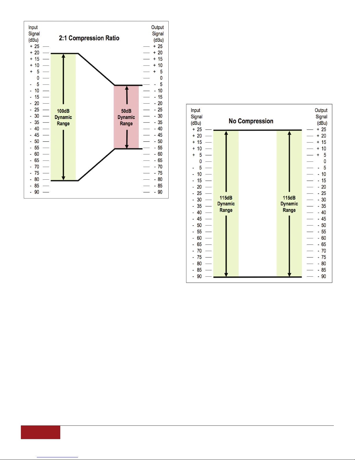
In order to achieve 100dB of dynamic range, which
is considered to be a minimum for high quality audio,
an analog wireless microphone compresses 100dB of
input dynamic range by a ratio of 2:1 in order to have it
fit within 50dB. This compression is achieved by using
a “VGA”, or Variable Gain Amplifier, with its gain being
adjusted as a function of the average signal level being
input. Louder signals are reduced in level, and/or softer
signals are increased in level, so that the overall dynamic
range is smaller.
On the receiver side, expansion is required, again using
a VGA, in order to attempt to restore the original dynamic
range. In this case, louder signals are made louder, and
or softer signals are made softer, such that the original
dynamic range is restored. The combination of these two
processes is known as “companding” (a combination of
compressing and expanding).
Unfortunately, companding does create some sonic
artifacts. Depending on the time constants used to
analyze the signal level and “decide” on the gain the
VGA is set to, gain changes can become audible,
creating a sound often called “breathing”. This can be
heard most obviously when a loud transient sound
occurs, causing the VGA gain to quickly reduce level to
compress the signal. After the transient has passed, the
VGA gain is gradually returned to “normal”, during which
time any other sound or noise can be heard to increase
in volume, or breathe. Additionally, the expander on the
receiver has no knowledge of the original input signal,
so its ability to restore the original dynamic range is
dependent on the manufacturer’s accuracy of matching
the time constants and gain control between the
transmitter and receiver.
Audio Transmission
Due to FCC regulatory bandwidth limitations, analog
FM has a less than ideal dynamic range and frequency
response for transmitting audio signals. These inadequacies require analog FM wireless microphones to perform
signal processing on both the transmitter and receiver.
Line 6, Inc. | Wireless Microphone Technology Guide
9
Page 10
The result is a reduction in the residual noise present in
analog FM wireless systems, but at the cost of reduced
dynamic range in higher frequencies due to the higher
gain of these frequencies at the transmitter.
Digital wireless systems are able to transmit the digital
audio signal without any compression or limiting, or
Pre-emphasis/De-emphasis. It also can accommodate a
wider input dynamic range, eliminating the need for level
controls. The result is that the input signal is accurately
reproduced at the receiving end.
Additionally, the dynamic range of the original audio
signal can exceed 100dB. In order to accommodate this,
the transmitter usually has a user adjustment for level
control. If a singer is clipping the input, then the
transmitter’s signal level must be adjusted downward,
and the receiver’s level must be proportionally adjusted
upward to maintain unity gain. Typical FM transmitters will
also include an additional audio processing section called
a “limiter”. This function prevents an overload condition
of the audio signal which can cause distortion. The limiter
also prevents “overmodulation” (excessive frequency
deviation) of the RF signal. Overmodulation results in
the RF signal deviation exceeding the bandwidth of the
receiver, resulting in additional distortion. The limiter
prevents the audio signal from exceeding a preset
maximum level.
Dynamic range in analog systems is further reduced in
high frequencies due to a technique called Pre-emphasis/
De-emphasis. Pre-emphasis is the act of boosting high
frequencies in the audio band and De-emphasis is the
act of cutting high frequencies in the audio band. These
methods are used to improve signal to noise during
transmission. The boosted high frequencies produce a
larger deviation of the RF carrier thus creating a larger
signal compared to the existing RF noise floor. Once the
signal is received, the De-emphasis reduces the high
frequencies, also reducing noise in the process.
Distortion
The term Distortion is used to describe any
nonlinearity in a system, which can result in altering
the intended sound. The nature of companders introduce
a nonlinearity that results in an increased level of
distortion. Additionally, high level signals can cause
overmodulation distortion. Most analog wireless systems
specify their Total Harmonic Distortion at a level in which
the compander is steady and no overmodulation can
occur. In these conditions, the THD specification is
typically 0.1% to 0.5%.
In a digital wireless system, the distortion is a
function of the overall linearity of the system. There is
no compander, nor any audio overmodulation possibility.
The signal remains linear throughout the dynamic range,
10
Line 6, Inc. | Wireless Microphone Technology Guide
Page 11
resulting in a typical Total Harmonic Distortion
specification of 0.03%, an order of magnitude
improvement.
Frequency Response
The frequency response of an analog wireless system
is limited at both the low and the high end. On the low
end, it is necessary to roll off frequencies that would
interfere with the companding circuitry. For example, a
frequency of 20Hz is slow enough to cause the gain to
change with each cycle of the waveform. Therefore, low
frequencies are filtered out. The high frequencies are
limited by the constraints of analog FM technology, which
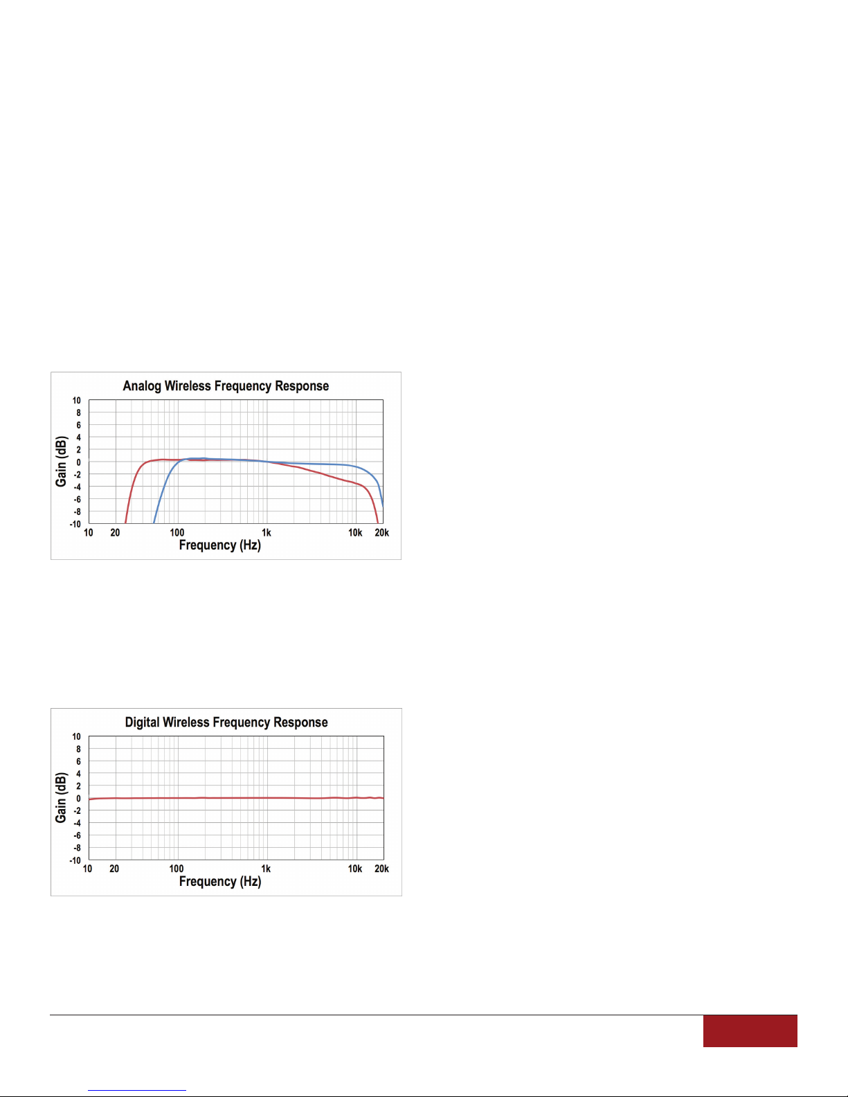
typically cannot produce frequencies above 15kHz. The
following graph shows the wireless frequency response
of two popular brands:
response, it allows the characteristics of the microphone’s
response to remain unaltered.
Summary
Line 6’s digital technology brings a number of
advantages to the world of wireless microphones.
By overcoming the limitations of analog systems,
wireless can now be used with all the reliability, ease,
and sonic benefits of a wired microphone.
Digital Benefits
• Ultra-Simple set up and use
• No interference from broadcast TV
• No frequency coordination per location
• All 2.4GHz channels work world-wide
• No license required
The high frequency response of a digital wireless
system is a function of the sample rate, and not any
aspects of the RF transmission.
Also, since there is no compander, the low
frequencies do not need to be rolled off. As a result,
a digital wireless system can transmit signals flat
between 10Hz and 20kHz.
• No Pre-emphasis/De-emphasis
• No companding
• No limiting
• No gain, pad or squelch adjustments required
• >115dB dynamic range
• 10Hz – 20kHz frequency response
• 0.03% Total Harmonic Distortion
• Audio quality unaffected by RF interference
These graphs represent the frequency response
of the wireless systems, independent of the microphone
element frequency response. Each microphone has its
own tonal response, which can determine the character
of its sound. If a wireless system has a flat frequency
Line 6, Inc. | Wireless Microphone Technology Guide
11
Page 12
Make the right choice at line6.com/wireless-microphone
Digital wireless is better. And Line 6 XD-V digital wireless
microphone systems are exceptional. Each one delivers
unmatched wireless performance, simplicity, and sound on
every stage around the world – license free. Our 4th-generation
digital technology makes sure of it. You can put your faith in
ancient analog technology, or you can simply choose digital.
XD-V Digital Wireless Systems
Over a decade of digital innovation
XD-V30 XD-V70XD-V BELTPACKS
 Loading...