

Page 1

®
XD-V75 Digital Wireless
Pilot’s Handbook
Manuel de pilotage
Pilotenhandbuch
Pilotenhandboek
Manual del Piloto
取扱説明書
40-00-0330 also available @ www.line6.com/manuals Rev A
Page 2
Important Safety Instructions
CAUTION
RISK OF ELECTRIC
SHOCK DO NOT OPEN
WARNING : TO REDUCE THE RISK OF FIRE OR ELECTRIC SHOCK, DO NOT REMOVE SCREWS.
NO USER-SERVICEABLE PARTS INSIDE. REFER SERVICING TO QUALIFIED SERVICE PERSONNEL.
WARNING : TO REDUCE THE RISK OF FIRE OR ELECTRIC SHOCK, DO NOT EXPOSE THE
APPLIANCE TO RAIN OR MOISTURE.
THIS DEVICE COMPLIES WITH PART 15 OF THE FCC RULES. OPERATION IS SUBJECT TO THE
FOLLOWING TWO CONDITIONS: (1) THIS DEVICE MAY NOT CAUSE HARMFUL INTERFERENCE,
AND (2) THIS DEVICE MUST ACCEPT ANY INTERFERENCE RECEIVED, INCLUDING INTERFERENCE THAT MAY CAUSE UNDESIRED OPERATION.
Warning: Changes or modifications not expressly approved in writing by Line 6 may void the users authority to
operate this equipment.
RF Exposure Statement: This transmitter must not be co-located or operated in conjunction with any other
antenna or transmitter.
Note: This equipment has been tested and found to comply with the limits for a Class B digital device, pursuant
to part 15 of the FCC Rules. These limits are designed to provide reasonable protection against harmful interference in a residential installation. This equipment generates, uses and can radiate radio frequency energy and, if
not installed and used in accordance with the instructions, may cause harmful interference to radio communications. However, there is no guarantee that interference will not occur in a particular installation. If this equipment
does cause harmful interference to radio or television reception, which can be determined by turning the equipment off and on, the user is encouraged to try to correct the interference by one or more of the following measures:
- Reorient or relocate the receiving antenna.
- Increase the separation between the equipment and receiver.
- Connect the equipment into an outlet on a circuit different from that to which the receiver is connected.
- Consult the dealer or an experienced radio/TV technician for help.
This Class B digital apparatus complies with Canadian ICES-003.
Cet appareil numerique de la classe B est conforme a la norme NMB-003 du Canada.
The FCC compliance sticker is attached to the THH12 battery compartment.
Remove the THH12 base by unscrewing counter clockwise to see this compliance sticker.
CERTIFICATION
Page 3
You should read these Important Safety Instructions.
Keep these instructions in a safe place
Before using your XD-V75 Digital Wireless System, carefully read the applicable items of these operating
instructions and the safety suggestions.
1. Obey all warnings in the XD-V75 manual.
2. Do not perform service operations beyond those described in the XD-V75 Manual. Service is required when
the apparatus has been damaged in any way, such as:
•liquidhasbeenspilledorobjectshavefallenintotheapparatus
•theunithasbeenexposedtorainormoisture
•theunitdoesnotoperatenormallyorchangesinperformanceinasignicantway
•theunitisdroppedortheenclosureisdamaged
3. Do not place near heat sources, such as radiators, heat registers, or appliances which produce heat.
4. Guard against objects or liquids entering the device. Do not use or place unit near water.
5. Do not step on cords. Do not place items on top of cords so that they are pinched or leaned on. Pay particular attention to the cord at the plug end and the point where it connects to the device.
6. Clean only with a damp cloth.
7. Only use attachments/accessories specified by the manufacturer.
8. Prolonged listening at high volume levels may cause irreparable hearing loss and/or damage. Always be sure
to practice “safe listening.”
N222
20546/SDPPI/2011
3794
20544/SDPPI/2011
3794
(01)07899153000059
(01)07899153010271
Page 4

Thank you for your purchase of the XD-V75 Digital Wireless microphone system. It is a sophisticated
digital wireless system, yet is easy to configure and use within minutes. With its fully digital transmission,
the system provides features and benefits that differ in some ways from previous generations of analog
wireless, but in most respects you use it just like other wireless systems. By understanding a few simple
concepts, you’ll be able to achieve superior audio quality, a secure and dropout-free signal, and the
ability to use multiple channels of wireless together without interference or other conflicts.
•Digital transmission in the 2.4 GHz band – license-free operation worldwide
•Avoids interference from high-power TV transmitters in the UHF bands
•Digital technology provides the audio response of a cable, without companding – 24-bit digital
converters, up to 120 dBA dynamic range, and 10 Hz – 20 kHz bandwidth
•4th-generation technology promotes reliable, dropout-free performance
•Fast setup: gain, squelch, or level adjustments not required
•14 channels that work together simultaneously
•300 foot (100 meter) range
•Microphone modeling of popular vocal mics
•Beltpack EQ modeling for headset, instrument, and lavalier mics
•Accurate battery-life indicators on both transmitter and receiver
•Real-time LCD indicators display critical performance parameters, including RF and link
status, diversity mode, and operating channel
•User-selectable secure digital encryption
•Advanced setup menus on receiver and transmitters provide additional parameter adjustments
•Built-in antenna distribution and rugged, rack-mountable design
4
Page 5

Recommendations foR Best PeRfoRmance
•Maintain a clear line of sight between the transmitter and receiver antennas. Typically the
receiver antennas should be above head level. Avoid placing the receiver in the bottom of the
rack unless remote antennas are employed.
•Avoid placing the receiver behind walls. When this is necessary the receiver’s antennas should
be remotely located as to be in sight of the transmitter.
•Avoid placing the receiver in close proximity to RF generating equipment including computers,
wireless access points and microwave ovens.
•Point the antennas up and 45 degrees from vertical while avoiding touching metal objects like
rack or rack rails.
•Avoid blocking antennas in the transmitters. Do not “cup” the bottom of the handheld
transmitter. Avoid placing the beltpack transmitter in pockets.
suPPlied comPonents
XD-V75 Receiver (RX212): receiver; 9V / 0.5A external universal power supply; short rack ear; long
rack ear with D-holes for front-mounting antennas; two (2) BNC-to-BNC connectors; two (2) BNCto-BNC cables; two (2) half-wave articulating antennas (RDrac); dovetail “key” to join two receivers
for rack-mounting; square mounting bracket to “lock” the rear panels together; user’s manual.
THH12 Handheld Transmitter: transmitter; two (2) AA alkaline batteries; mic stand clip; fitted case.
or
TBP12 Beltpack Transmitter : transmitter; two (2) AA alkaline batteries; fitted case; optional lavalier
mic with windscreen and clip, headset mic with windscreen, instrument mic with windscreen and clip,
or instrument cable with quarter-inch connector.
Note, A full line of accessories is available to support the application of the XD-V75 digital wireless
microphone systems including: remote antenna, cables, cases, an antenna distribution system and
individual transmitter, receiver and microphone components. Please visit www.line6.com for more
information.
5
Page 6
Xd-V75 digital WiReless Quick setuP
Receiver
1
2
3 4 5
ANTENNA A ANTENNA B
MUTE
TRANSMITTER
STATUS
A OUT
RFBATTERYAUDIO
MAIN OUTS
UNBAL BALANCED
CH 1:THH12
8:00
XD-
2.4GHz DIGITAL WIRELESS SYSTEM
7
9VDC IN
USB
B OUT
PUSH TO SET
86
9 10
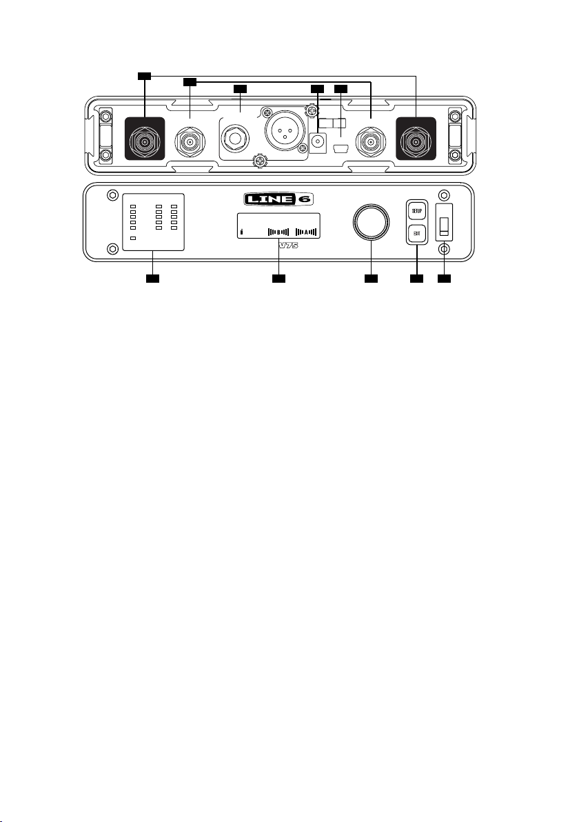
1. Antenna A & B Input Connectors (BNC)
2. Antenna A & B Output Connectors (BNC) – to daisy-chain multiple receivers
3. Unbalanced 1/4-Inch and Balanced XLR Audio Output Connectors
4. 9VDC Power Input Connector
5. USB Connector –
for firmware updates
6. Transmitter Status LED Displays
AUDIO
– lights green to indicate audio signal level, top clip LED lights red to indicate the audio
is clipping
MUTE – lights red when transmitter is muted
BATTERY – lights green, with all lit indicating full transmitter battery; bottom LED turns red
when 1 hour remains, and flashes red when less than 40 minutes remains
RF – lights green to indicate transmitter signal strength/quality; with transmitter off, red lights
indicate interference on that channel
7. LCD Display Panel – main page shows channel, transmitter, battery life, and antenna strength;
display also functions as programming window
8. Edit / Push to Set ROTARY ENCODER – used to change and set receiver parameters
9. Setup Button / Exit Button – used to access setup menus; EXIT returns to main display page;
these buttons are used along with the
ROTARY ENCODER
10. Receiver Power Switch
Plug the power supply cable into the receiver and AC power, and connect the antennas. Turn on the
receiver, press the
press to select. Scroll to the desired channel and press to select. Press
SETUP button, and with the ROTARY ENCODER scroll to SET CHANNEL and
EXIT. Connect with an audio
cable to a mixer or similar. The receiver is ready to use.
6
Page 7

Beltpack Transmitter
BATT AUDIO
MUTE
6
OFF/ON
BATT AUDIO
N222
8
7
4 5132
008WWA090153
IC: 6768A-916TBP12
FCC ID: UOB916TBP12
Pat. Pending
Made in China
Designed in U.S.A.
1. ON / OFF Switch
2. Mini-XLR (TA4) Input Connector
3. MUTE Switch
4. SELECT
5. VALUE
6. Battery & Audio Status LEDs –
Battery LED is blue when good, red when low, flashing when very
low; Audio LED is green for audio signal and red for clipping.
7. LCD Display Panel – Backlight will light briefly when transmitter is turned on and when changing
pages; will stay lit when muted; display also functions as programming window.
8. Belt Clip – Can remove the center mounting screw to reposition or remove, as necessary.
Open the battery door on the side of the beltpack and insert two AA batteries. Slide the
switch to turn on. Press and hold the
number will appear on the LCD screen. Press the
channel number to match the receiver. Press and hold the
SELECT button for two seconds, and CH and a flashing channel
VALUE button repeatedly in order to change the
SELECT button for two seconds to select and
ON/OFF
return to the main screen. The transmitter is ready to use.
7
Page 8
Handheld Transmitter
MUTE SELECT
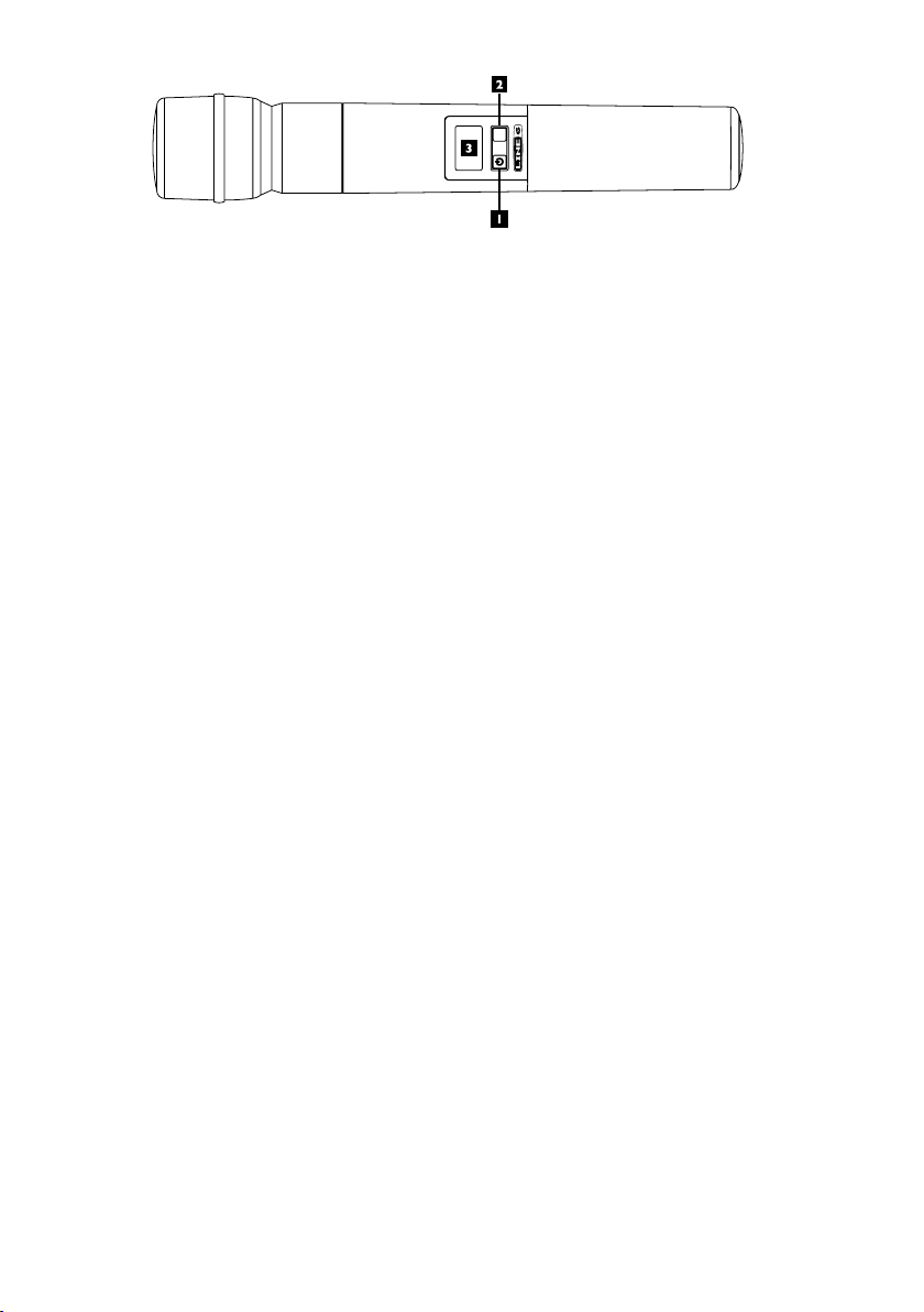
1. Power / Mute Button – Press briefly to turn on; press and hold for two seconds to turn off. Press
and hold for one second to mute; press briefly to unmute. When in Setup Mode, press this button
to change the value of the parameter one step at a time.
2. Select Button – Press and hold for two seconds to enter Setup Mode; press briefly to go to next
setup page; hold two seconds to exit setup and save changes.
3. LCD Display Panel – Backlight will light briefly when transmitter is turned on and when changing
pages; will stay lit when muted; display also functions as programming window.
Unscrew the transmitter base and insert two AA batteries. Push the
and hold the
the LCD screen. Press the
match the receiver. Press and hold the
SELECT button for two seconds, and CH and a flashing channel number will appear on
On/MUTE button repeatedly in order to change the channel number to
SELECT button for two seconds to select and return to the main
screen. The transmitter is ready to use.
On/MUTE button to turn on. Press
8
Page 9
What makes a WiReless digital?
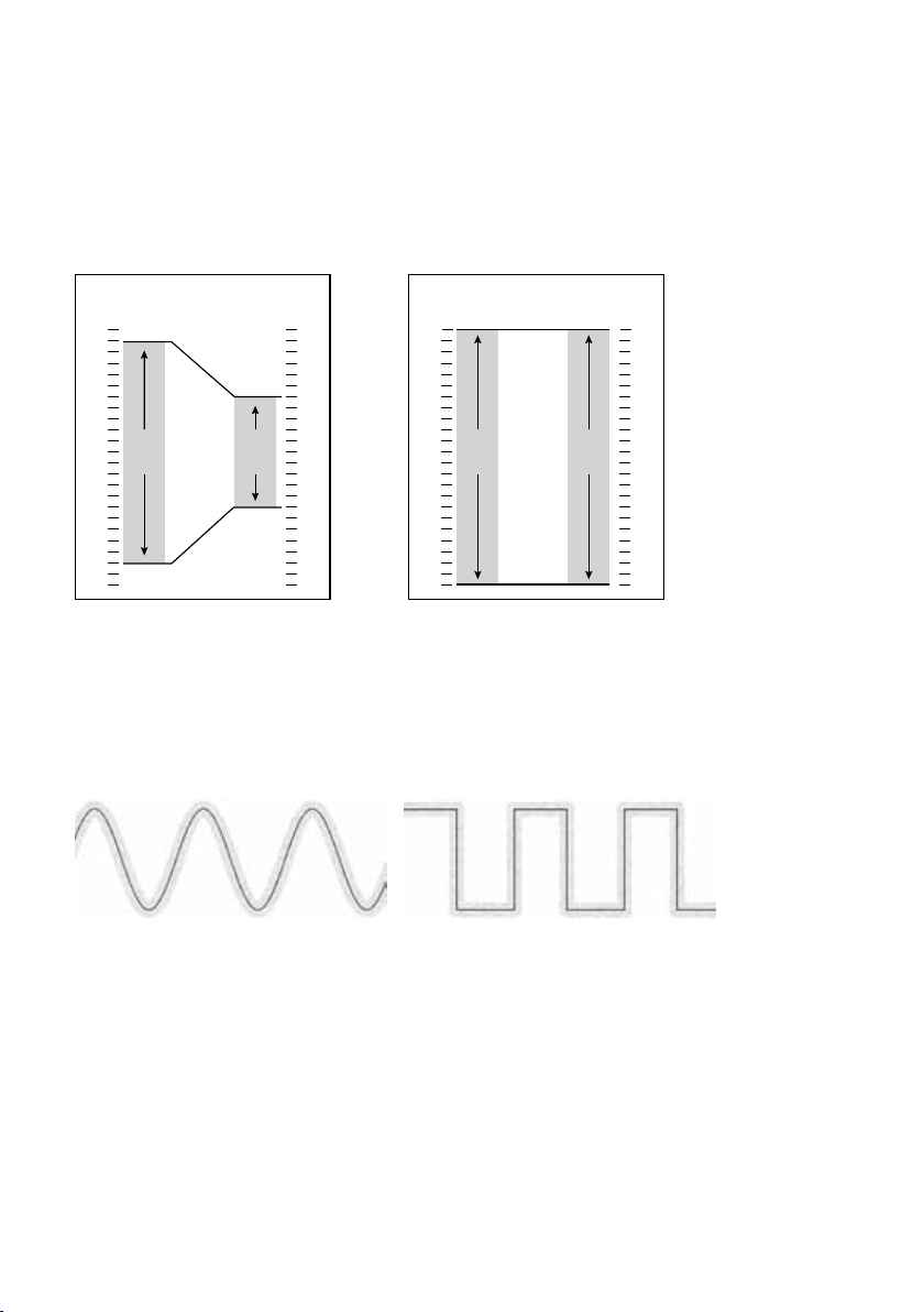
In a typical analog wireless microphone system the signal between the transmitter and the receiver
consists of a very high frequency radio wave carrier that is continually varied slightly in frequency by
the audio signal from the microphone (or other transducer). The electronic circuitry in the receiver
removes the carrier frequency and leaves the audio signal – the same principle that is used in FM radio
broadcasts. The signal is highly compressed upon transmission and expanded at the receiver – the origin
of the word “companding.” Analog transmissions are vulnerable to many interference effects from other
RF and electromagnetic signals – and the interference is usually audible as well as having the effect of
shortening range or rendering the channel unusable.
Input
Signal
(dBu)
+ 25
+ 20
+ 15
+ 10
+ 5
- 5
- 10
- 15
- 20
- 25
- 30
- 35
- 40
- 45
- 50
- 55
- 60
- 65
- 70
- 75
- 80
- 85
- 90
0
2:1 Compression Ratio
100dB
Dynamic
Range
50dB
Dynamic
Range
Output
Signal
(dBu)
+ 25
+ 20
+ 15
+ 10
+ 5
- 5
- 10
- 15
- 20
- 25
- 30
- 35
- 40
- 45
- 50
- 55
- 60
- 65
- 70
- 75
- 80
- 85
- 90
0
Input
Signal
(dBu)
+ 25
+ 20
+ 15
+ 10
+ 5
- 5
- 10
- 15
- 20
- 25
- 30
- 35
- 40
- 45
- 50
- 55
- 60
- 65
- 70
- 75
- 80
- 85
- 90
0
No Compression
115dB
Dynamic
Range
115dB
Dynamic
Range
Output
Signal
(dBu)
+ 25
+ 20
+ 15
+ 10
+ 5
- 5
- 10
- 15
- 20
- 25
- 30
- 35
- 40
- 45
- 50
- 55
- 60
- 65
- 70
- 75
- 80
- 85
- 90
0
Digital wireless microphone systems provide a much more robust and interference resistant performance.
Within the microphone transmitter, the audio signal from the voice or other source is digitally sampled,
and the sample is converted into a digital “word” consisting of the electrical equivalent of a string of
1’s and 0’s. As in analog wireless, a very high frequency carrier wave is modulated, but in this case with
the digital “stream” of samples so that the carrier frequency only has two distinct states that represent
the signal in the same manner that the flat areas and pits on a CD represent the music. The receiver
retrieves this information from the carrier and decodes it via a D/A converter and outputs an audio
signal that is the replica of what was encoded at the mic.
Analog signal with noise Digital signal with noise
Benefits of Digital Wireless
As mentioned above, analog wireless transmissions are susceptible to a variety of noise and interference
conditions, related to signal strength and/or interference from external electronic devices and other
wireless signals. These can ride along with the carrier frequency and its audio signal as added noise,
affect the receiver directly because the antennas that pick up the transmitter signal are also wide open
to pick up other radio signal in the same general RF band, or interact with the carrier frequency to create
additional harmonic frequencies. Problems can come from sources as diverse as a television broadcast
signal, other wireless mics in use, digital signal processors, or even malfunctioning fluorescent lighting
ballasts or other electrical devices.
While the same physics applies to a digital signal riding on a carrier wave, the digital signal with just two
states is more difficult to damage. If the receiver finds that something has come in that is not equivalent
9
Page 10
to a digital word of 1’s and 0’s, that information will be ignored. If noise is riding on those digital words,
it is still decoded as one of two states – rather than something in-between, if it were analog. As long as
the digitally modulated carrier arrives at the receiver’s antenna with sufficient level, it will be accurately
decoded. And as with CD players and other digital audio devices, error concealment algorithms may be
added to fill in the gaps where there is missing information.
Typically with a digital wireless system, the signal will retain its quality until the signal level is too low,
and then it’s gone. The main effect that interference has on a digital wireless system is that it will shorten
the maximum range between the transmitter and receiver antenna. To alleviate potential problems,
maintain line-of-sight between transmitter and receiver, locate the receiver / receiver antennas at a
distance from interfering sources such as WiFi routers, and use the HI setting on the transmitter when
operating at longer distances.
Xd-V75 ReceiVeR detailed setuP
For stand-alone placement, position the receiver on a level surface where the front-panel controls and
displays are visible. Connect the supplied DC-1G power supply to the
panel; to secure, press a loop of the cable through the cable holder located above the connector to
prevent accidental disconnection. Plug the power supply into an available AC outlet that provides
voltage from 90 – 240 VAC.
Place the supplied half-wave articulating antennas (RDrac) on to the outer left and right BNC
connectors marked
position the antennas at an approximately 45 degree “rabbit ears” orientation. For details on frontmounting antennas when rack-mounting, or connecting multiple receivers, see Antenna Mounting
and Placement.
On the right side of the front panel, turn on the power switch; the display will light. Press the
button. The two-line display will show [SELECT FUNCTION] in the top position, and turning the
ROTARY ENCODER will scroll through a list of editable functions. Scroll to [SET CHANNEL] and
press the
ROTARY ENCODER to select; pressing the SETUP button also will select the function.
ANTENNA A and ANTENNA B. Rotate a quarter-turn clockwise, and then
9VDC In connector on the rear
SETUP
CH 1:THH12B
8:00
Note, Turn clockwise to scroll down the list, and counterclockwise to return to the top of the list.
The [SET CHANNEL] edit page will show the currently selected channel. Turn the encoder to change
the channel; any channel number other than the one currently selected will flash. Press the
ENCODER to select the new channel.
Note, The receiver’s RF channel will not actually change to a different frequency until the ROTARY
ENCODER is pressed.
To sync the handheld or beltpack transmitter to the receiver, follow the procedure in the following
transmitter quick setup sections. For more details on scanning channels and using multiple wireless
units together, see Channel Scanning Procedure, Range and Interference Testing, and Minimizing Near / Far
Transmitter Effects.
To adjust the output level of the receiver going to the mixing console or other audio equipment, see
Audio Output and Filter Adjustments.
Note, The receiver provides three display modes. The Main Page shows the currently selected channel,
transmitter name or designation, remaining battery life, and the performance of antennas A and B. The
[SELECT FUNCTION] page has a scrollable list of editable receiver operations. The Edit page allows
changes to be made to the currently selected function. The only user operations available are pressing
SETUP and EXIT, and turning or pressing the ROTARY ENCODER knob.
10
SET CHANNEL:
14
ROTA RY
Page 11

thh12 handheld tRansmitteR detailed setuP
To begin, twist the bottom section of the THH12 transmitter counterclockwise, unscrew and remove
it. Lightly pull the battery cover tab down with a thumbnail, and open the cover by pulling back; it is
hinged at the base of the transmitter. Insert two AA batteries, noting the polarity markings shown in
the battery compartment.
Note, Use alkaline batteries, or rechargeable NiMH batteries in the 2400 – 2800 mAh range. See
Battery Level Indicator Functions, for more details.
AA BATTERY
Close the battery cover and replace the bottom section of the transmitter. Press and briefly hold the left
ON/MUTE button located below the display. The top line shows the currently selected channel, and the
bottom line shows remaining battery life. The backlight will light for a few seconds, and then turn off.
Note, The transmitter buttons are recessed to prevent accidental activation, so press them down firmly
below the recessed surface, until you feel a click. Avoid using pointy objects such as ball point pens.
The transmitter must be set to the same channel as the receiver it is to work with (if the receiver is on
channel 9, the transmitter must also be set to channel 9). Press and hold the
SELECT button for two
seconds, and the display will show CH on the top line, and the currently selected channel on the second
line. Press the
ON/MUTE button to go through channels 1 through 14, with each click incrementing
to the next channel; the channel number will flash. At the desired channel, stop and press and hold the
SELECT button for two seconds (or do not press any button for 15 seconds). The transmitter will then
change to the newly selected frequency, and return to the main display. Check the receiver display to
confirm that the transmitter signal is being received.
When the transmitter is on, a quick push of the ON/MUTE button will mute the audio from the mic,
and the backlight will remain lit while it is muted. The word [MUTE] will appear on the display.
Another quick push will un-mute it. The THH12 transmitter has other editable functions, including
high and low power modes, selectable microphone models, encryption options, and the ability to give
the transmitter a 6-character name that will show on both the transmitter and receiver displays. For
more details, see Setting Microphone Models and Encryption.
11
Page 12

Note, The transmitter can be locked so that the user cannot accidentally or deliberately make changes
to its settings during use. To set the lock, unscrew the bottom section of the transmitter, go to the back
side of the battery compartment, and flip the small micro-switch to the right to lock; the display will
show the image of a lock in the lower left corner, and the word [LOCKED] will appear whenever a
button is pushed. Replace the bottom section to use. To unlock, flip the switch to the left position, and
then changes can be made and the transmitter can be turned off.
tBP12 BeltPack tRansmitteR detailed setuP
To begin, press the small oval battery lock button on the left side of the transmitter (same side as the
antenna and
The battery door will flip open. Insert two AA batteries, noting the polarity markings on the metal insert
on the inside of the door. Close the battery door and slide the battery latch to the original position.
Slide the
remaining battery life.
Note, Use alkaline batteries, or rechargeable NiMH batteries in the 2400 – 2800 mAh range. See
Battery Level Indicator Functions, for more details.
The beltpack transmitter has a TA4M 4-conductor connector for lavalier, headset, and instrument
microphones or a quarter-inch instrument cord to be attached. The microphone must have a TA4F
connector to mate with the beltpack. Align this connector until it slides easily into the beltpack, and
press down until it is seated. To remove, press the button on the side of the TA4F connector and pull
straight out. For more on the application of lavalier and headset mics, see Microphone Usage Tips.
OFF/ON slide switch), and slide the rubberized rectangular latch up toward the switch.
OFF/ON switch to the On position; the display will show the currently selected channel and
The transmitter must be set to the same channel as the receiver it is to work with (if the receiver
is on channel 9, the transmitter must also be set to channel 9). Press and hold the
SELECT button
for two seconds, and the display will show [CH] on the top line, and the currently selected channel
on the second line. Press the
VALUE button to go through channels 1 through 14, with each click
incrementing to the next channel; the channel number will flash. At the desired channel, stop and
press and hold the
SELECT button for two seconds (or do not press any button for 15 seconds). The
transmitter will then change to the newly selected frequency, and return to the main display. Check the
receiver display to confirm that the transmitter signal is being received.
12
Page 13

When the transmitter is on, a quick push and hold of the
backlight will remain lit while it is muted. The word [MUTE] will appear on the display. Another quick
push will un-mute it. The TBP12 transmitter has other editable functions, including high and low
power modes, selectable microphone settings, encryption options, and the ability to give the transmitter
a 6-character name that will show on both the transmitter and receiver displays. For more details, see
Setting Microphone Models and Encryption.
MUTE button will mute the audio, and the
connecting the Xd-V75 ReceiVeR
The receiver features a balanced XLR and unbalanced (tip-sleeve) quarter-inch connector. To connect
to a mixing board or powered mixer, use a microphone cable between the receiver output and the
mixer’s mic-level input – in the same way as you would connect a wired microphone. In its [NORMAL
(+0 dB)] setting, the output of the XD-V75 receiver is virtually identical to that of the microphone on
the transmitter (and the microphone models on the THH12 handheld transmitter emulate the output
levels of the particular microphones they model). If desired, the output can be adjusted in 1-dB steps
from -18 dB to +12 dB via [SELECT FUNCTION: OUTPUT ADJUST]; see Audio Output and Filter
Adjustments for details.
To connect to an instrument amplifier or other audio equipment with a quarter-inch connector such as
a signal processor or effects unit, use a quarter-inch to quarter-inch instrument cable. The output level
adjustment also affects this connector.
Note: Do not use TRS balanced cable to connect to unbalanced output. The ring of the TRS connection
on the ¼” out is a digital communication line used to talk with other Line6 wireless products. Connecting
a TRS in this manner may create some digital noise when connected to a balanced audio input on a
mixing console. Only an unbalanced ¼” inch cable is recommended for this audio output usage
comPatiBility With otheR line 6 WiReless deVices
The XD-V75 utilizes our latest digital wireless transmission method, and is fully channel compatible
with the XD-V35, as well as Relay™ G30, Relay™ G50, and Relay™ G90 models that have Version 2
software running RF2 mode. Multiple units of any of these models can be mixed used within the same
location as long as each is on a unique channel and no more than 14 are used simultaneously.
The XD-V75 receiver can also automatically receive transmissions from the previous generation of Line
6 wireless products, which include the XD-V30, XD-V70, and Relay™ G30, Relay™ G50, and Relay™
G90 models with Version software, now referred to as RF1 mode. However, it is not recommended to
mix usage of the RF1 and RF2 modes within the same location due to the channel frequencies in each
system not being compatible.
If an XD-V75 unit is being added to a setup that already includes any devices running in RF1 mode,
the XD-V75 can be used to update the older devices to run RF2 mode by using an internet-connected
computer attached to the XD-V75’s USB port. See the Firmware Updating Procedure section for more
information. Alternatively, the XD-V75 transmitters can be setup to operate in RF1 mode if it is necessary
to use the transmitters with older Line 6 receivers. To set the THH12 or TBP12 transmitters into the
RF1 mode, enter Setup mode to display the current channel, then while holding down the
button press and release the
display will briefly show [XD-V75 RF1] or [XD-V75 RF2] to indicate whether it is operating in the old
or new mode, respectively. This setting is retained when powering off, so as a reminder the display will
also show this indication [RF1 or RF2] each time power is turned on. The XD-V75 receiver will display
a [To] on the far right of the display to indicate while communicating with a RF1 software transmitter.
ON/MUTE button on the THH12 or VALUE button on the TBP12. The
SELECT
13
Page 14

channel scanning PRoceduRe
Though the Line 6 wireless microphone system operates in the unlicensed 2.4 GHz band – above the
frequencies used by most wireless microphone systems, cellular phones, and other voice communication
devices – the band is not unused, and does include WiFi routers. The receiver contains a sophisticated
scanning capability that can determine the existence of interfering wireless devices that would
compromise the performance range of operation on certain channels, and can also help assure that the
selected wireless mic channels do not interfere with other wireless devices. Use the following procedure
to minimize interference; if you are adding new wireless units to a previous installation with Line 6
systems, first turn on the existing transmitters so their frequencies can be detected.
Press the
the
scanning process. After approximately 6 seconds, the display will show channel numbers 1 through 14
on the bottom line, with a status indicator above each channel. The indicators and their applications
are:
SETUP button on the receiver. The [SELECT FUNCTION] screen will appear; scroll with
ROTARY ENCODER to [CHANNEL SCAN], and press the ROTARY ENCODER to begin the
Blank
Little to no RF – best channels to select for use
XD-V70-class transmitter already on and using that channel
(or other Line 6 wireless systems operating in RF1 mode)
XD-V75-class transmitter already on and using that channel
(or other Line 6 wireless systems operating in RF2 mode)
Non-Line 6 low-level RF signal – can use these channels with
minimal effect on range
Non-Line 6 medium-level RF signal – using these channels will
likely result in lessened range for that particular transmitter
Non-Line 6 high-level RF signal – using these channels will
result in a significantly compromised range of operation.
The currently selected channel number for the receiver will be underlined.
Note, No audio will function while the receiver is on this channel-scanning page; you must select a
channel by pressing the
ROTARY ENCODER or press the EXIT button and leave the page to resume
audio.
Turn the
channel number as you scroll. Once you have highlighted a blank, unused channel, press the
ENCODER to select it. The receiver display will return to the main page with the new channel number
ROTARY ENCODER to scroll through the list of channels; a flashing underline will follow the
ROTA RY
shown.
Note, Any of the channels can be selected, regardless of the RF conditions displayed for the channel.
Selecting a channel showing significant RF interference can result in lessened range for the associated
transmitter.
Turn on the transmitter you would like to use with the receiver, and use the procedure described in the
Quick Start section to set it to the same channel number. To set up multiple receivers and transmitters,
leave each set on as you scan with the next receiver and select another open channel. Alternately,
after you have performed the scan with the first receiver, note all the open channels with little or no
interference, and set the remaining receiver / transmitter pairs to those channels.
14
Page 15

Note: Make sure all powered on Line6 TX units are a minimum of 2 meters away from scanning RX
antennas. This will avoid overload and incorrect scanning function while in this mode.
audio outPut & filteR adjustments
Receiver Output Level Adjustments
The default receiver output from the XD-V75 receiver is +0 dB or unity gain. This allows the wireless
unit to use the same mixer gain levels as the equivalent wired microphone, and connect to the mic-level
input of the mixer. If a boost or attenuation from this level is required, the level may be adjusted, using
the following procedure.
OUTPUT ADJUST:
+0dB (NORM)
Press the SETUP button, and under [SELECT FUNCTION] scroll with the ROTARY ENCODER to
[OUTPUT ADJUST]. Press the
show a value ranging from -18dB to +12dB. In default mode it will show [NORMAL (+0 dB)], and will
increment in 1 dB steps through the range, going clockwise to increase the level and counterclockwise
to decrease it.
When the desired level is reached, press the
screen. As you turn the
go into effect immediately.
Typically, you will use the [NORMAL] or unity gain position, and use the trim or gain control and the
channel knob or fader on the mixer to boost or attenuate the signal level. This setting will usually result
in the best overall audio system signal-to-noise ratio. With a mix of wired and wireless microphones,
using the [NORMAL] position will allow you to keep the channel faders and trim controls at similar
positions for similar audible levels. If your mixer just has channel level knobs with no additional trim or
gain control, you might choose to make modest level changes at the receiver.
Note, Raising the receiver’s output level, even to the maximum +12 dB, is not equivalent to a line-level
signal. Use the mic-level setting / input on the mixer or other audio device that is next in the signal
chain.
Boosting the output level at the receiver can give less headroom before clipping its output, adding
distortion on the microphone peaks. You will typically add gain at the receiver only when the user of the
microphone is either speaking too softly or is too distant from the microphone and it is more convenient
to add it there rather than at the mixer level control, or if your receiver’s signal is going to a device that
has no level control and you require more level. Return to [NORMAL] when the situation is corrected.
Attenuating the output level substantially can lower the signal-to-noise ratio, resulting in more noise
and hiss coming through the speakers. You will typically add attenuation at the receiver only when the
receiver output is clipping the mixer or other audio device input and there is no attenuation control
available at the mixer.
Note, The general rule of audio gain staging is to enable as much gain as possible at each stage of the
audio signal, while keeping the level below clipping at the input / program peaks. This process starts
with the microphone element itself, and making sure the user is providing a good signal by not having
the mic too far away or speaking too softly. In this case, the [NORMAL] setting on the XD-V75 receiver
should provide the next gain stage with adequate level with enough headroom to prevent clipping. The
trim or gain control on the mixer is the next stage to adjust level, keeping it below clipping on peaks.
The channel fader follows, and then either the subgroup fader or the main mixer output level to the
amplifier. Obtaining the best level at each stage in the audio chain means you will need less gain at the
amplifier to reach the same output level from the speakers, and will be amplifying less electronic hiss
and noise and more of the desired signal.
ROTARY ENCODER and increase or decrease the gain, the level changes will
ROTARY ENCODER to select. The bottom line of the display will
ROTARY ENCODER to select and return to the main
15
Page 16

Dynamic Filter Adjustments
The dynamic filter allows users to select from [OFF] (no filtering), [NORM] (for music applications),
and [TALK] (for spoken word applications). When active, the filter minimizes handling noise and stage
vibrations, via a downward expander with a dynamic high-pass filter. In the [NORM] mode, when
the microphone input level falls below a fixed threshold, overall level is reduced by approximately 6
dB while simultaneously rolling off frequencies below 200 Hz. The [TALK] setting increases the level
reduction which is more appropriate for speech applications.
To change the dynamic filter setting, press the receiver
FILTER]. Press the
ENCODER to select that setting and return to the main menu. The dynamic filter becomes immediately
ROTARY ENCODER to select, and scroll to the desired setting. Press the R OTA RY
SETUP button and scroll to [DYNAMIC
active upon selection.
Note, For applications where the microphone is not in close proximity to the mouth or the performer
is speaking/singing at low levels, best results may be obtained by setting the Dynamic Filter to the OFF
setting.
setting micRoPhone models
Selecting Mic Models with the THH12 Handheld Transmitter
The THH12 handheld microphone transmitter features selectable models based on a number of popular
vocal microphones, including their audio quality, frequency response, and output level. The models
include the Shure
AE4100, Electro-Voice
®
SM58® and Beta58® and SM57®, Sennheiser® e835 and e935, Audio-Technica®
®
N/D767a, Audix® OM5, and AKG® D5.
Note, The models begin with the response parameters of the Line 6 microphone element, and shape
it to attain the characteristics of other microphones. Some physical characteristics of these other
microphones, such as their off-axis response, polar pattern, and proximity effect are unable to be
duplicated with a single mic element.
To select a particular microphone model, press and hold the
to the channel setting screen. Quickly press the
SELECT button two more times to go to the [MODEL]
page. You will see a two- or three-digit designation for the currently selected mic model; press the
MUTE button to scroll through the available models – one per click. The model names will flash. To
select one of the models, press the
SELECT button (the display goes to the next page of selection
SELECT button until the display changes
ON/
options) or do not push any buttons for approximately 15 seconds.
Display Manufacturer Model
L6
58
b58
57
835
935
41
767
o5
d5
Line 6 Custom
®
Shure
®
Shure
®
Shure
Sennheiser
Sennheiser
Audio-Technica
Electro-Voice
Audix
AKG
®
®
®
®
®
SM58
Beta 58
SM57
e835
e935
®
AE4100
N/D767a
OM5
D5
16
Page 17

Note, In a production using both wired and wireless microphones, the modeling allows the user to select
a wireless mic model that is similar to the majority of wired ones. This selection should help reduce
potential feedback from dissimilar microphone frequency responses when using global EQ settings on
the audio system.
*All product names herein are trademarks of their respective owners, which are in no way associated or affiliated with Line 6. These trademarks of
other manufacturers are used solely to identify the products of those manufacturers whose tones and sounds were studied during Line 6’s sound model
development. SHURE and SM58 are registered trademarks of Shure Incorporated. Sennheiser is a registered trademark of Sennheiser Electronic Corp.
Audix is a registered trademark of Audix Corporation. Audio-Technica is a registered trademark of Audio-Technica Corporation. Electro-Voice is a
registered trademark of Telex Communications, Inc. AKG is a trademark of AKG Acoustics GmbH.
Selecting Equalization Models with the TBP12 Beltpack Transmitter
The TBP12 beltpack transmitter may be used with a wide variety of lavalier, headset, and instrument
microphones, as well as with a quarter-inch instrument cable. Some of these microphones are available
from Line 6; with the correct wiring and a TA4F connector, virtually any mic may be used. To help
the user achieve the best performance from the microphones in a multitude of applications, sets of
equalization models are provided.
Note, See the TA4F wiring instructions in the Appendix at the end of the manual.
To select a particular equalization model for a lavalier, headset, or instrument microphone, press and
hold the
SELECT button two more times to go to the [MODEL] page. You will see a three-digit designation for
the currently selected mic EQ model; press the
– one per click. The model names will flash. To select one of the models, press the
(the display goes to the next page of selection options) or do not push any buttons for approximately
15 seconds.
SELECT button until the display changes to the channel setting screen. Quickly press the
VALUE button to scroll through the available models
SELECT button
Name Application Description
SF1 Speech Filter 1 Gentle high-pass
SF2 Speech Filter 2 Gentle high-pass and high-cut
SF3 Speech Filter 3 Moderate high-pass and high-cut
SF4 Speech Filter 4 Gentle high-pass, mid-cut and high-cut
SF5 Speech Filter 5 Moderate high-pass, mid-cut and high-cut
SF6 Speech Filter 6 Aggressive high-pass, mid-cut and high-cut
IF1 Instrument Filter 1 Guitar cable high frequency roll-off
IF2 Instrument Filter 2 Woodwind instrument enhancement
IF3 Instrument Filter 3 Brass instrument enhancement
Microphone Usage Tips
Unlike a handheld microphone where the user typically speaks or sings directly into the mic element
– where the full frequency response of both the person and the mic is available, lavalier microphones
are placed on the body in a variety of places. Being farther away from and below or to the side of the
mouth, the level is usually much lower, plus the frequency response lacks the highs as well as the lows
from being near the mic element. The sound is often hollow and emphasizes the midrange. When you
increase the gain to bring back the level of the voice, other extraneous noises are also more easily picked
up and amplified.
The sometimes substantial equalization corrections necessary to make the voice of the lavalier user
sound “natural” can be quite difficult to achieve without feedback problems, especially with live audio
at higher levels. Using a combination of mic placement and EQ is the best compromise for good sound
17
Page 18

at usable levels – and the transmitter’s EQ response models will help the process.
Try to maintain a constant distance and relationship between the user’s mouth and the microphone. In
live theatre this is often done by placing a small mic in the hairline toward the front side of the head or
right above the ear. With mic placement on the collar or shoulder area, changes in level can occur as the
user’s head turns; experiment with the location of the mic to minimize this effect. Mic placement in the
center of the chest can help with the level changes, but is farther from the voice and quite shielded from
the direct energy of the voice, so typically provides a hollow midrange or “chest” sound to the voice.
Directional (cardioid) lavalier microphones can help isolate the voice of the user from the background
noise that may be picked up by an omnidirectional mic. They are more sensitive to the movements of
the user’s head, with more change in level when speaking toward or away from the front of the mic. In
addition, they are more prone than omni mics to handling and cable noise, so the user needs to be more
careful about movement. The lavalier EQ models in the TBP12 beltpack provide a high-pass filter (lowend rolloff) to help reduce this extraneous noise.
When appropriate, a headset microphone can solve most of these problems of level, compromised
frequency response, feedback potential, handling noise, and pickup of background sounds. A number of
low-profile models are available. To minimize breath noise and pops from certain consonants, use the
mic’s wind filter and position the mic element toward the corner of the mouth.
In a situation where the audio is recorded or broadcast rather than live, or the user has a significant
distance between his/her location and the speaker system, substantial equalization changes and a more
natural sound are easier to achieve.
setting otheR tRansmitteR functions
Naming Transmitters
The handheld transmitter has a default name of [THH12] and the beltpack of [TBP12]. The transmitters
can be given a six-character name to readily identify them on both the transmitter and its associated
receiver. Using the [NAME] function, transmitters can be given a six-character name that will show
on the main screen of the LCD display; the name is transmitted to the receiver and also appears on the
receiver’s main display page. The character set includes letters and numbers (plus a dash and blank), so
you can identify them by the user’s name or by their function, as desired.
To name the transmitter, press and hold the SELECT button until it changes to the channel select
page. Quickly press the
position is [OFF]. Press the
to select [ON]. Press the
name) appears with the first letter flashing. Press the
through the alphanumeric list until the desired letter or number appears; when reached, press
to keep it and go to the next character. When the final character has been reached, press and hold
the
SELECT button to go back to the main screen. The name shows on the transmitter screen and is
18
SELECT button four more times until you reach the [NAME] page. The default
ON/MUTE button on the handheld or the VALUE button on the beltpack
SELECT button, and the default name (or if already named, the transmitter’s
ON/MUTE or VALUE button repeatedly to scroll
SELECT
Page 19

transmitted to the receiver and displayed on the receiver LCD main page.
Transmitter Power Level Select
The Line 6 digital transmitters give the option to select a lower power transmission, which is useful for
minimizing interference when using them along with WiFi or other 2.4 GHz devices, and for extending
battery life when the transmitters are used closer to the receiver antennas. When you are using wireless
systems on the same channels at nearby venues or stages, the lower power setting will often allow them
to work at each location without interfering with each other. For maximum range, use the (default)
higher power setting.
To set the transmitter power, press and hold the SELECT button until the channel screen appears.
Quickly press the
button on the handheld or the
Save). Press and hold the
Note, If the transmitter is set at LO power and you experience short range or interference, change it to
SELECT button one more time to reach the [POWER] screen. Press the ON/MUTE
VALUE button on the beltpack to change between [HI] and [LO] (Power
SELECT button to select and go back to the main screen.
the HI setting to increase the range. Alternately, position the transmitter closer to the receiver antennas,
make sure the antennas are line-of-sight, or select another frequency that has less interference.
Locking, Unlocking, and Muting the Transmitter
The THH12 and TBP12 transmitters can be locked to prevent accidental button pushes from handling
during use. When locked, the user cannot mute or turn off the transmitter, or change the frequency or
other settings, assuring that an error with a transmitter will not interrupt the event. After use, it is easy
to unlock the transmitter to turn off or change settings. When not locked, the transmitter can be muted
so that it keeps transmitting but audio is temporarily disabled.
MUTE SELECT
BATT AUDIO
OFF/ON
MUTE
To mute the THH12 handheld, quickly press the ON/MUTE button until it clicks; press again to
unmute. The word [MUTED] will appear in place of the transmitter name, and the backlight will stay
lit. To mute the TBP12 beltpack, push and briefly hold the
MUTE button on the top of the pack; press
again to unmute. The display works identically to the handheld. When the mic is muted and you press
the
SELECT button to enter another parameter page, the word [MUTED] will remain in tiny characters
in the left center of the display as a reminder. When a transmitter is [MUTED] the red
MUTE LED will
light on the receiver.
To lock the THH12 handheld, turn it on and assure that the desired settings are completed, and that the
receiver display shows the signal. Unscrew the end of the battery compartment, and locate the microswitch on the back; move it to the right toward the lock symbol. Test by pressing the
SETUP buttons, and the word [LOCKED] will appear on the top line of the briefly lit display. Unscrew
ON/MUTE or
the compartment and move the switch to the left to unlock.
19
Page 20

To lock the TBP12 beltpack, turn it on and check the settings, and check the receiver display for signal.
Press together and hold
With two fingers, press the
SELECT and VALUE buttons at the same time and hold for two seconds.
The word [LOCKED] will appear on the top line of the display for a moment, and then revert to the
main screen. Test by pressing any of the buttons to assure that it is locked. Locking will also temporarily
disable the
OFF/ON switch. To unlock, again hold the SELECT and VALUE buttons for two seconds.
Setting Encryption
The XD-V75 Digital Wireless microphone system permits a unique 24-bit encryption code to be
applied to the audio coming from the transmitter, creating a secure link between it and the associated
receiver – over 16 million codes are possible. Encryption prevents the audio signal from being captured
and deciphered when wireless is being used during confidential meetings and proceedings. The audio
entering the microphone element is encoded within the transmitter, and is decoded within the receiver;
the radio signal in between is secure.
The encryption code is entered into the transmitter first, and then is transferred to the associated
receiver. Make sure that you have already set both to the same frequency.
“Send” crypto key function both transmitter and receiver will need to be set to the same channel and
communicating in non-Crypto mode before this feature can be used. With the transmitter on, press and
hold the
SELECT button to go to the channel page, and then press the button three more times to go to
the [CRYTPTO] page. The encryption mode is either [OFF] or [ON], and the word will flash; press
MUTE on the handheld or VALUE on the beltpack to switch between them. Choose [ON] to set a code.
Note, The transmitter will begin transmitting in encrypted mode when [ON] is selected and setup mode
is exited. If you are going through the edit screens and do not want to change the current encryption
setting, pressing the
SELECT button again without pressing ON/MUTE or VALUE will bypass this page,
leaving encryption in its current off or on state, and go on to the next edit page. To turn off encryption,
go to the [CRYPTO] page, press the
ON/MUTE or VALUE button to go to [OFF], and press the SELECT
button to exit. In a few moments, the system will return to the unencrypted transmission mode.
The transmitter automatically and randomly generates a six-digit hex code (characters 0 – 9 and A – F),
which it uses for encryption and remembers even when the transmitter is turned off. The only way to
“lose” this code is to turn the [CRYPTO] page to [OFF]. The code may be seen only once, by pressing
the
SELECT button immediately after setting [CRYPTO] to [ON]; it will appear on the backlit display
for two minutes or until the
SELECT button is pressed again to go to the next page. As soon as SELECT
is pressed for the second time, the transmitter will go into encrypted mode.
To transfer the encryption code to the associated XD-V75 receiver that is set to the same channel, the
receiver must be on the encryption page. Press the SETUP button to go to [SELECT FUNCTION] and
scroll with the
ROTARY ENCODER to [ENCRYPTION], then press the encoder to enter that function.
Note, When using the
ON/
20
Page 21

Scroll with the
cursor underlining the letter A. If you need to go to [NEW KEY 2], pressing the
ROTARY ENCODER to go to [MODE: AUTO SENSE / NEW KEY 1: xxxxxx], with the
ROTARY ENCODER
once more will advance the cursor to the number 1, and turning the encoder will go to number 2.
Pressing the
ROTARY ENCODER one more time will advance it to the first character of the six-digit
code, which will flash and change as the encoder is turned.
MUTE SELECT
RFBATTERYAUDIO
MODE: AUTO SENSE
TRANSMITTER
MUTE
STATUS
Note, Two encryption key “slots” are provided on the receiver, so that you can use two encrypted
NEW KEY1: xxxxxx
XD-
2.4GHz DIGITAL WIRELESS SYSTEM
PUSH TO SET
transmitters at different times with the same receiver – for example, having a handheld and beltpack at
the ready for a receiver. The encryption keys are generated at the transmitter, so they will be different
for each one; use [NEW KEY 1] for the first and [NEW KEY 2] for the second.
The easiest way to transfer the encryption code to the receiver is to have the transmitter nearby (no
more than a few feet away from) the receiver, and put the receiver into encryption mode described
above before generating the code in the transmitter. When the code is displayed in the transmitter
display, press and continue holding the
ON/MUTE on the handheld or VALUE on the beltpack to
transmit the code to the receiver; you will see Snd appear in the transmitter display. At the same time,
while on the receiver’s [MODE: AUTO SENSE] page with the cursor on the first digit of the code, press
the
ROTARY ENCODER after the transmitter completes transmitting the code to the receiver, then
release the button on the transmitter.
Note, After the transmitter has been set to encryption mode, the main display page will show the letters
CR in place of the normal CH to indicate that transmissions are encrypted.
Alternately, the code can be manually transferred to the receiver. Either write down the code from
the transmitter display and later enter it into the receiver on the [ENCRYPTION] page, or bring the
transmitter to the receiver during the two minutes the code is displayed and manually enter what is on
its display. To manually enter an encryption code from the [MODE: AUTO SENSE / KEY 1 (or 2):
xxxxxx] screen, press the
then turn the
ROTARY ENCODER until the desired character appears. Press the encoder again and the
ROTARY ENCODER until it is on the first x character which will flash, and
next character can be changed. Continue this process until the last character has been entered, and
then press the
ROTARY ENCODER one last time to store the code.
MODE: OFF
NEW KEY1: 54Axxx
Note, Though the direct transmission of the encryption code from the transmitter to the receiver is
faster and secure, since it is done at very low power in close proximity to the receiver, some users may
want to make sure that the code is never transmitted –thus the ability to enter it manually. Also,
for redundancy, in some cases the user might want to have two receivers in place holding the same
encryption code for the transmitter, with the second one as a backup.
To change to a new encryption code, when using a currently encrypted transmitter with another
receiver or desiring a fresh code, first go to the [CRYPTO] page on the transmitter. Using the
MUTE or VALUE button, change the setting from [ON] to [OFF] and press SELECT to cancel the
ON/
21
Page 22

previous code. Then hold
Follow the same procedure as before to view the code on the transmitter and transfer it automatically
or manually to the receiver.
During the operation of the system, if the receiver is receiving a signal from a transmitter that is
encrypted, and the matching code has been stored, a lower-case letter c will appear on the upper right
corner of the display. If the correct code is not in the receiver, or encryption has been turned off at the
receiver, the display will read [BLOCKED]. Audio cannot be received until the code has been entered
into the receiver, or a new code has been generated at the transmitter and transferred to the receiver.
SELECT to re-enter setup mode, go to [CRYPTO], and select [ON] again.
Battery Level Indicator Functions
Line 6 transmitters contain battery level indicators that can accurately assess the remaining battery life,
and show this information on both the transmitter and the associated receiver. These indicators are
calibrated to commercial alkaline batteries, and can also provide useful information when used with
rechargeable batteries.
When the transmitter is turned on, the bottom line of the display will show the remaining battery
life in hours and minutes, with a battery icon next to the time. The remaining battery life is shown in
increments of twenty minutes (Hours:20). The initial time indicated just after the transmitter is turned
on, and for the first few minutes, will often show more time than is actually remaining – this is due to
the characteristic of alkaline batteries to temporarily increase in voltage for a short time after a period of
rest. For best accuracy, wait about twenty minutes after transmitter turn-on to rely on the time indicator.
CH 1:THH12B
8:00
On the receiver, the remaining battery life will be shown on the display in the lower left-hand corner of
the main page, and changes in sync with the transmitter’s indicator. In addition, the middle 5-position
LED ladder indicates remaining battery life in one-hour steps. When remaining battery life is more than
five hours, all five LEDs are lit, with between four and five hours left, four LEDs are lit, and so on. When
less than one hour of battery life remains, the bottom LED will turn from green to red – and will begin
to flash in the last 40 minutes of life.
NiMH (nickel metal hydride) batteries in the 2400 – 2800 mAh range are recommended as rechargeable
batteries to use with the THH12 and TBP12 transmitters. Make sure that the batteries fit properly in the
battery compartments to prevent damage, since these batteries can vary in diameter and length. They
need to be charged in the correct external battery charger; the transmitters are not designed for batteries
to be charged internally. Because the transmitter’s battery meter was calibrated for alkaline batteries,
they will not be as accurate in calculating the remaining battery life when using rechargeable batteries.
Note, Carbon-zinc batteries are not recommended.
22
Page 23

Range and inteRfeRence testing
The frequency scanning capability of the XD-V75 receiver, plus the A / B antenna metering on the
display and the RF LED ladder, provide powerful tools for selecting the clearest channels, avoiding
interference, and preventing the wireless microphone systems from interfering with other wireless
devices. Using these functions before operating the systems in new locations will ensure trouble-free
and compatible performance.
Scanning the Channels for Interference
The first step is to scan the channel using the process in Channel Scanning Procedure. Channels
1 – 14 are spread across a 76 MHz band of the 2.4 GHz spectrum, and the frequencies are specially
selected for compatible operation and to minimize interference with other equipment working in the
same spectrum. Perform a scan with all transmitters off at first when in a new location.
Once the scan is complete, look at the results on the channel display, especially noting any channels
with the half block or full block icon above them. This indicates significant existing interference to
those channels, which will limit the range of transmitters using those channels (and also means that a
transmitter on that channel could interfere with the existing other equipment).
Detecting Interference with the RF Meter
RFBATTERYAUDIO
TRANSMITTER
MUTE
STATUS
The XD-V75 receiver has an LED ladder (stacked LED meter) labeled RF, which detects signals on the
channel frequencies to which it is currently set (for example, when set to Line 6 channel 7, it detects
frequencies with either a 2.433 GHz or 2.467 GHz center frequency). These LED’s are green when
receiving signal from a Line 6 transmitter, and red when the transmitter is off and interfering signals on
that frequency are present. If the receiver is on and the associated transmitter is off, and one or more
of the LEDs on the RF meter are lit red, it is detecting a potentially interfering signal. The more LEDs
that are lit, the stronger the signal – and the more it will interfere with the range and performance of a
transmitter on that channel.
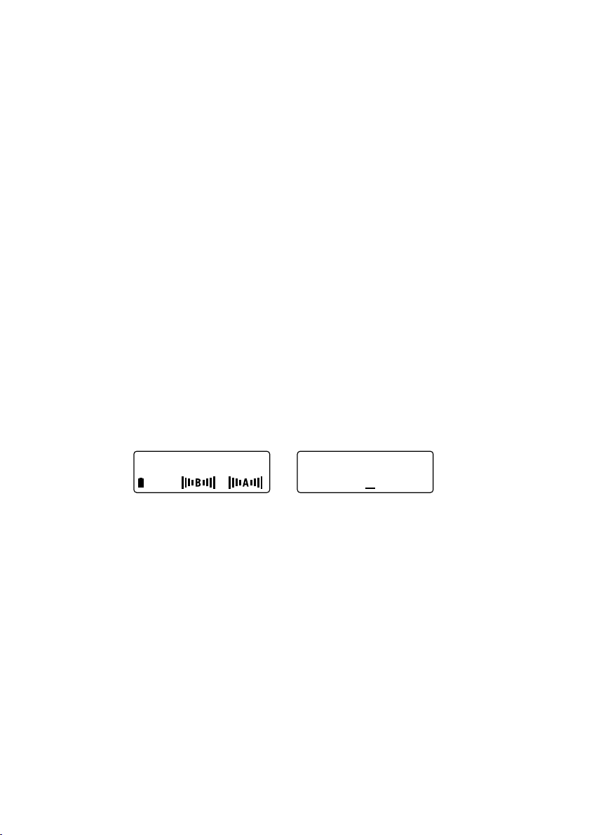
Detecting Interference with the Antenna A & B Display
The main receiver display page shows the received signal strength on antennas A and B for both of
the frequencies emitted from the associated Line 6 transmitter. They can also show the presence of
interfering signals when the transmitter is off.
The four vertical bars (Antenna Bars) that can appear on the left and right sides of the A and B on
the display represent increasing levels of RF signal – with 4 bars being the highest level. With the
transmitter off, the appearance of one or more bars next to those letters shows a potentially interfering
signal on that channel which can affect the performance and range of the wireless system.
23
Page 24

Since the XD-V75 transmitters use two frequencies simultaneously, the bars to the left of each letter
represent the lower of the two frequencies, and the bars to the right of each letter the higher frequency.
In some cases, only one of the two frequencies will show interference. The following chart describes the
potential effect on performance.
Antenna Bars Estimated Line 6 Usability Interferer Signal Strength Estimated Line 6 Maximum Range
4 Bad >(-60dBm) 0-10ft
3 Poor >(-70dBm) 1-25ft
2 Fair >(-80dBm) 25-50ft
1 Good >(-90dBm) 50-100ft
0 Excellent No interference >200ft
Note, When the associated handheld or beltpack is on, these same bars show the transmitter’s signal
strength at the receiver’s antennas for both frequencies on the channel. During normal operation, you
should see four bars on both sides – and as you begin to exceed the range you will see fewer bars. At
three bars the signal will still be good, and at two it should still be acceptable and provide reliable audio.
Walk-Testing the Performance Area
When first setting up a wireless system in a new location, it is good practice to position the receiver and
its antennas where they will remain during the event, and then walk the entire performing area with the
audio system on and the transmitter active. Talk and listen for signal dropouts or other problems, and
note where they are with respect to your antenna placement.
If you for some reason cannot turn on the audio system, with one person to walk with the transmitter
and another to monitor the receiver, you can use the RF meters to find locations with low signal strength
that could potentially cause problems. You can also monitor the signal through a headset connected to
the mixer, if the receiver has been connected to it.
If you are using remote antennas, you can reposition them to obtain better coverage and improve or
eliminate areas with lower signal strength. With the antennas connected to the receiver, you can place
it where it has better line-of-sight to the transmitter.
Note, If there are still spots where poor signal reception occurs, mark the problem areas on the floor
with removable tape and let the user know to avoid those areas.
Avoiding WiFi Interference
If you see several half or full blocks that are adjacent to each other on the channel scan screen, it is
likely that you are seeing a WiFi channel that is operating in the same location. If you can locate that
equipment and position your receivers farther from it, or remote the receiver antennas farther from it,
the interference may lessen in strength. Also be aware that your transmitters may interfere with the
WiFi network operation if they are transmitting close to the routers or other WiFi connected devices.
The best option when you see strong interfering signals is to use the other available Line 6 channels
that are clear.
The most commonly used WiFi channels (note that their numbering does not correspond with Line
6 channels) are channels 1, 6, and 11. These channels each cover 20 MHz of spectrum, and usually
only one WiFi channel will be in use in a location. In the majority of cases, any of the Line 6 wireless
channels will be compatible with existing WiFi with minimal to no interference, and in all cases you
will be able to use eight channels of Line 6 wireless while completely avoiding the WiFi channel. Use
the channels in the chart located in the manual Appendices, Channel RF Frequency Chart.
Note, Cellular phones with Bluetooth or WiFi capabilities transmit signals in the 2.4 GHz band, so are
a potential source of interference when near the receiver antennas. Use these functions of your phone
24
Page 25

at least a few feet away from the receivers when you are operating the wireless system.
minimizing neaR / faR tRansmitteR effects
Line 6 digital wireless systems are designed so that a receiver only passes audio from a transmitter that
is set to the same channel. While other nearby transmitters and RF sources will not create audio in a
receiver not on their channel, under certain conditions they can have an effect on range. When you are
using several channels of wireless, following some simple procedures will minimize any near / far effects.
The XD-V75 receiver constantly monitors the signal from its transmitter, and increases gain (sensitivity)
as the transmitter moves farther away to maintain a good RF signal level. The near / far effect can
happen when the transmitter is at a distance from the receiver’s antennas, and transmitters on different
channels are being used near the antennas. The strong signal from the nearby transmitters, especially
if they are close in frequency to the channel the receiver is set on, can mask the signal from the distant
transmitter – and sometimes cause the audio from that transmitter to drop out.
For example, if the transmitter on the same channel as the receiver is 50 feet away, and another
transmitter is 3 feet from the receiver’s antenna, the range of that distant transmitter might be affected.
Avoid this potential problem by positioning the receivers and their antennas at a more equal distance
from the transmitters that are in use.
Solutions include:
•Making sure that any transmitter is at least 6 feet away from the receivers, and that other RF
sources (such as WiFi routers) are also at a distance from them.
•Placing the antennas higher, which can lessen the difference in distance as well as increase
line-of-sight with the distant transmitter.
•Using remote antennas and placing them approximately equidistant from each group of
transmitters (for example, positioning a remote antenna connected to
the closer transmitters, and one connected to
•Moving the receiver associated with the distant transmitter closer to it, or using remote
antennas attached to that particular receiver to get closer.
•Using the LO transmitter power setting for the nearby transmitters, and the HI power setting
for the distant transmitter.
ANTENNA B nearer to the distant transmitters).
ANTENNA A nearer to
antenna mounting and Placement
The XD-V75 receiver may be used stand-alone, or may be rack-mounted. When used by itself and placed
on a surface, the antennas are typically mounted on the rear and connected to the BNC connectors
labeled
ANTENNA A and ANTENNA B. For rack-mounting, Line 6 has provided a variety of options,
including a long rack ear with cutouts for mounting the supplied BNC connectors to front-mount
antennas, a pair of BNC cables to connect the receiver to those antennas, and hardware to connect
two of the half-rack receivers side-by-side in one rack space. Multiple receivers can share one pair
of antennas via looping connectors on the back of the receiver. And optional remote antennas are
available.
Note, When rack-mounting receivers, it is preferable to keep them – and their associated antennas –
toward the top of the rack so that line-of-sight to the transmitters is unobstructed for the best range
and performance. Also, keep receivers and equipment such as digital signal processors, computers, WiFi
wireless routers, and other devices that emit RF energy as separated from each other as possible.
Rack Mounting One Receiver with Front-Mounted Antennas
25
Page 26

To rack-mount a single XD-V75 receiver, use both the long and short rack ears provided with the
receiver; the receiver can be mounted on either the left or right side of the rack. If you are not using
optional remote antennas, you will be mounting the provided half-wave antennas on the long rack ear.
Remove the rubber covers to expose the D-cut mounting holes in the rack ear, unthread the hex nut and
lock washer from the provided BNC-to-BNC connectors, pass them through the holes, and rethread
and tighten. Use the four provided short flat-head screws to attach the right-angle tabs of the rack ears
in the dovetail slots at the front of the receiver.
To connect the antennas to the receiver, attach one end of the provided BNC cables to
and
ANTENNA B on the rear panel, and the other end to the inside-facing side of the BNC-to-BNC
ANTENNA A
connectors on the long rack ear. Complete the process by screwing the assembly into the rack, making
your power and audio connections, and placing the half-wave antennas on the connectors on the front
of the rack mount.
Rack Mounting & Antennas – Two Receivers
To mount two receivers side-by-side, use the provided “dovetail key”. Slide it into the channel on one
side of the receiver from the rear toward the front. The key fits tightly, so some pressure or gentle taps
from a mallet may be required; take care to avoid damage to the exposed front-panel controls when
positioning the receiver for this process. Then slide the slot of the second receiver on to the dovetail
key, starting at the point where the key is closest to the front of the first receiver, and push back until
the front panels of the receivers meet.
Part of the dovetail key may still be protruding from the back of the receivers, and the mallet can be
used to gently tap until it is flush with the rear of the receivers. At the center of the rear panel where
the two receivers meet, use a 1/8” Allen wrench to remove the inner rubber “bumpers”, and place the
square rack-mount mating bracket onto the unit so that the holes line up with the screw holes in each
receiver. Replace the rubber bumpers and attach with the screws you removed.
Use the short flat-head screws to attach short rack ears to both sided of the block of two receivers. When
the receivers are mounted together, either use remote antennas on one receiver and BNC-to-BNC
cables to loop to the other.
To loop from one receiver to the next, the antennas connect to the
B BNC connector or the rear panel of the first receiver. Then the BNC-to-BNC cables go from the
[A OUT] and [B OUT] connectors to the
ANTENNA A and ANTENNA B connectors of the next
receiver.
ANTENNA A and ANTENNA
26
Page 27

Note, For best performance, Line 6 recommends that no more than four receivers share a single pair
of antennas via looping through the BNC ports on the rear of the receiver. For the next group of four
receivers, use another pair of antennas. Alternately, use a Line 6 antenna distribution unit or other
RF distribution unit that is appropriate to the 2.4 GHz band to run multiple receivers from one pair of
antennas.
Note, Line 6 remote antennas are active and therefore require power through the coaxial antenna
cable to function properly. Make sure that any other RF distribution unit that is used can provide the
necessary power; consult the antenna specifications for details.
Remote Antenna Placement
The XD-V75 Digital Wireless system can be used with remote antennas, so that the receivers can be
located where convenient – even at a distance from where the transmitters are being used – yet the
antennas can be placed nearer to the transmitters for better RF reception. Remote antennas become
important especially when the distance is significant between the transmitters and receivers, there
are walls or other obstacles between them, or when the receivers are “permanently” mounted in an
equipment room or production vehicle and the transmitters are used at various and changing locations
and distances. Both omnidirectional and directional (cardioid) remote antennas are available.
To connect remote antennas to receivers, use low-loss 50-ohm coaxial cable with the appropriate BNC
connector on each end. Place the antennas with clear line-of sight to the location where the transmitters
will be used; the Line 6 model P360 omnidirectional and P180 directional active antennas provide the
convenience of mic stand mounting. Attach one end of the cable to the antenna, and run it the shortest
possible distance to the
Measure the distance and set the gain to the appropriate setting on the antenna; 6 dB for 25 feet, 15
dB for 50 feet, and 26 dB for 100 feet. Once connected and with the receiver on, confirm that the blue
light on the front of the antenna is lit. Walk-test the area after the antennas are placed to make sure
that it is properly covered without interference or dropouts. Up to three additional receivers can use this
antenna by looping the receivers.
Note, As the RF signal travels through the cable to the receiver, there will be some loss of signal level,
which at greater lengths and with higher loss cables can be significant. With a passive antenna, use the
lowest loss cable you can find and try not to exceed about 15 feet of length. With an active antenna that
provides additional gain, set it to the proper amplification for the cable length, and try not to exceed
100 feet of cable.
When used properly, remote antennas can increase range and lessen dropouts and interference
conditions, compared with having the half-wave antennas directly connected to the receiver or frontmounted in the rack. This is especially true when the receivers must be located in a non-line-of-sight
position or behind obstacles.
Omnidirectional antennas are best applied when the users will be transmitting from a wider area – in
front, to the sides, and even behind the antenna. Directional antennas provide greater signal strength
at the front of the antenna, and greater rejection of the signal at the rear – in the case of the P180,
a cardioid coverage pattern of approximately 90 degrees with a roll off to the sides. Use them when
the users are in a more confined area or not roaming as much. They can also be used to minimize an
interfering signal source by facing the back of the antenna toward the interferer and the front toward
the transmitters.
In some cases remote antennas can also allow you to use the transmitter’s low power setting to minimize
interference when transmitters are used very close together or two or more groups of transmitters are
used for separate productions that are closely located (such as in adjacent ballrooms or theatres). Just
make sure that the improved signal strength you receive from a closer and clearer position to the
transmitters is not overwhelmed by the losses of too long a cable run.
ANTENNA A / ANTENNA B connectors on the back of the receiver.
27
Page 28

aPPendices
Troubleshooting
Problem Solution
No Audio
Transmitter Stays On
Shorter Range
Signal Dropouts
Firmware Updating Procedure
The XD-V75 receiver features a USB port, which may be used for updating the firmware of both the
receiver and transmitter when new versions are released. This procedure is detailed on the Line 6
website (www.line6.com).
The XD-V75 receiver can be used to update the XD-V70 generation of transmitters to enhance their
feature set and compatibility with the XD-V75 receiver, and can also update the CPU in the XDV70 receiver (as well as the XD-V30, Relay™ G30, Relay™ G50, and Relay™ G90 receiver and
transmitters). When using both XD-V70 and XD-V75 units in the same installation, it is recommended
to upgrade the older units to the latest firmware. Details are also on the web site.
Switch on transmitter and/or receiver
Change transmitter batteries
Confirm proper polarity of batteries in transmitter
Transmitter audio muted; press MUTE button to unmute
Transmitter and receiver are on different channels; set to same channel
Transmitter encrypted and receiver not (or with different encryption code)
Receiver currently in Channel Scan or Channel Select mode
Receiver not connected to audio system, or audio system off or muted
Transmitter locked; unlock and then turn off
Antennas not connected to receiver; check connections
Receiver antennas not in line-of sight; raise them or clear obstructions
Interference from other source; change channel and see Near / Far in manual
Place receiver / receiver antennas farther from WiFi or other 2.4 GHz source
Too great a distance between transmitter and receiver; move them closer
Switch transmitter to HI power mode
Remote the antennas closer to transmitter
Keep receiver / antennas higher in line-of-sight; no doors or walls obstructing
28
Page 29

Channel RF Frequency Chart
The following chart shows the frequencies used by Channels 1 through 14. Each channel uses two
frequencies for greater reliability and redundancy. These frequencies are compatible with each other,
and chosen to work within an environment where WiFi is running. For best performance, do not place
receivers or transmitters in close proximity to WiFi routers or computers.
Channel Frequency A Frequency B Compatibility
1 2425 2475 Compatible with WiFi 1, 6, & 11
2 2422 2472 Compatible with WiFi 1, 6, & 11
3 2402 2450 Compatible with WiFi 1, 6, & 11
4 2447 2478 Compatible with WiFi 1, 6, & 11
5 2428 2453 Compatible with WiFi 1, 6, & 11
6 2430 2461 Compatible with WiFi 1
7 2433 2467 Compatible with WiFi 1
8 2436 2469 Compatible with WiFi 1
9 2413 2456 Compatible with WiFi 6
10 2416 2458 Compatible with WiFi 6
11 2407 2464 Compatible with WiFi 6
12 2405 2439 Compatible with WiFi 11
13 2419 2444 Compatible with WiFi 11
14 2410 2442 Compatible with WiFi 11
The following chart shows the WiFi channels, with the most commonly used Channels 1, 6, and 11
highlighted.
Channel
Frequency (GHz)12.41222.41732.42242.427
5
6
2.432
2.43772.44282.44792.452102.457112.462122.467132.472
29
Page 30

XD-V75 Digital Wireless System Specifications
System
Frequency Band 2.4GHz ISM Band
Compatible Channels 14
True Diversity Yes
Frequency Diversity Yes (2 Frequencies per channel)
Compander-Free Design Yes
Frequency Response THD % 10 Hz (-0.5 dB) - 20kHz (-2.5 dB)
System Latency < 2.9 ms (audio input to output)
Operating Temp Range 1 – 50 degrees C
Construction
XD-V75 Receiver
THH12 & TBP12 Transmitters
Receiver
Receiver Gain Control 0 dB nominal; -18 to +12 dB range
RF Performance Monitoring Yes (via LCD screen and LED)
Scanning and Channel Management Yes (via LCD screen and function menu)
RF Signal Strength Indicators 5-Segment LED
Audio Level Meter (on Receiver) 5-Segment LED
Dynamic Filter Yes (selectable)
Squelch & Pad adjustments None required
Number of Receiver Antennas 2
Receiver Format 1/2 RU (with included rack-mount kit)
Receiver Power Requirements 9Vdc 500mA
Output Impedance XLR: 150 Ohms Balanced
Sensitivity -95 dBm
Image Rejection 56 dB
Antenna Distribution A and B In & Out BNC Connectors
Antenna Impedance 50 Ohms
0.03% typical
Extruded aluminum chassis
Metal enclosures
1/4”: 1 kOhm Unbalanced
30
Page 31

Transmitters
Transmitter RF Output Power 10 mW HI; 3.3 mW LO
Battery Life 8 hours
Mic Modeling
THH12 Handheld
TBP12 Beltpack
Batteries 2 x AA Alkaline
Battery Display (on Transmitter) LCD Screen
Dynamic Range
THH12 Handheld
TBP12 Beltpack
TBP12 Maximum Audio Input Level 6.5 Vpp
TBP12 Beltpack Input Impedance 1.3 M Ohms
TBP12 Beltpack Supplied Bias Voltage 5 VDC (on Pin 2 of TA4F Connector)
Transmitter Audio Polarity Positive pressure on mic diaphragm produces
Yes (10 selectable models)
Yes (9 selectable EQ filters)
>115 dB
>120 dB
positive voltage
TBP12 Beltpack Pinout To TA4F Connector
Use the following wiring protocol when using other headset, lavalier, or instrument microphones or
cables with the TBP12 beltpack transmitter.
•TA4 pinout
•1 = GND
•2 = V+
•3 = Signal
•4 = Z (This pin is tied to Signal for lav mics and tied to Gnd or open for gtr)
31
Page 32

 Loading...