

Page 1

Linde warning projector
riginal instructions
O
3008011680 EN – 06/2018
Page 2

Page 3

Table of contents
1 Introduction
Linde warning projector ............................................... 2
Symbols used ...................................................... 2
Contact details ...................................................... 3
2Overview
Component overview ................................................. 6
3 Assembly
Assembling the Linde war
Projection size ...................................................... 9
ning projector ................................... 8
4 Operation
Inserting or replacing the gobo .......................................... 12
Focusing the warning
Aligning the warning pictogram .......................................... 13
pictogram ......................................... 13
5 Technical data
Dimensions ........................................................ 16
Technical data ...................................................... 16
g
Operating Instructions – 3008011680 EN – 06/2018 I
Page 4

Page 5

1
Introduction
Page 6
1 Introduction
Linde warning projector
Linde warning projector
Description of use
The Linde warning projector is a compact
high-power LED spotlight for projecting
warning pictograms.
The projection of warning p
clear and permanent visibi
the perception of dangers.
permanently visible, rega
dirt. Maintenance costs ar
is increased.
Warning pictograms are also clearly visible in
working environments with low light levels.
A selection of "gobos" (graphical optical
blackouts) can be used with the projector,
allowing individual adaptation to the ambient
conditions and the particular application.
To further increase occu
safety, the Linde warnin
combined with the Linde
warning unit. The warni
ictograms ensures
lity and thus aids
The warnings are
rdless of wear and
e reduced. Safety
pational health and
g projector can be
Safety Guard static
ng projector can
thereby be switched on when an industrial
truck approaches.
Intended use
The Linde warning projector is used solely to
project warning pictograms.
The warning projector is su
in industrial environment
on the ceiling, on walls or o
The projections do not exempt the drivers of
industrial trucks and pedestrians from their
legal duty of care to avoid any potentially
dangerous situations.
WARNING
Damage to eyes!
Do not look directly into the Linde
warning projector.
The Linde warning projector is assigned to risk
group 2 in accordance with DIN EN 62471.
itable for indoor use
s. It can be mounted
nstruts.
Symbols used
DANGER
Failure to comply can result in fatal injuries and/or
major damage to equipment.
WARNING
Failuretocom
and/or majo
2 Operating Instructions – 3008011680 EN – 06/2018
ply can result in serious injuries
r damage to equipment.
CAUTION
Failure to comply can result in damage to or destruction of the material.
NOTE
Explanation o
be evident eve
f technical context that may not
ntoaspecialist.
Page 7

Contact details
Manufacturer
Derksen Lichttechnik GmbH
Johannes-Rau-Allee 4
45889 Gelsenkirchen, Germany
Telephone: +49 (0) 209 98070-0
Fax: +49 (0) 209 98070-60
Email: info@derksen.de
Website: https://www.derksen.de/en/
Introduction 1
Contact details
Sales and service by:
Linde Material Handling GmbH
Carl-von-Linde-Platz
63743 Aschaffenburg, Germany
Telephone: +49 (0) 6021 99-0
Fax: +49 (0) 6021 99-1570
Email: info@linde-mh.de
Website: http://www.linde-mh.de
Operating Instructions – 3008011680 EN – 06/2018 3
Page 8

1 Introduction
Contact details
4 Operating Instructions – 3008011680 EN – 06/2018
Page 9

2
Overview
Page 10
2 Overview
Component overview
Component overview
8
1
9
2
7
3
4
5
6
1 Housing
2 Sleeve
3 Projector head
4 Sealing ring
5 Gobo holder
6 Operating Instructions – 3008011680 EN – 06/2018
6 Lens holder
7 Lens
8 Mounting plate
9 Bush for power supply
LWP_13
Page 11

3
Assembly
Page 12
Assembly
3
Assembling the Linde warning projector
Assembling the Linde warning
projector
WARNING
Risk of injury due to insecure mounting.
Mount the warning projector on constructions
that can bear four times the weight of the device.
Use suitable mounting material.
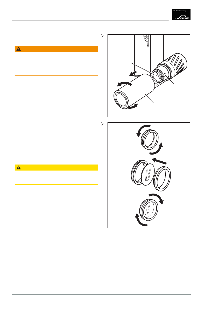
Unscrew four screws (1) along with spring
washers (2) and release the mounting plate
(3).
Remove the mounting plate.
Attach the mounting plate in the required lo-
cation. Use appropriate mounting material
to do so.
Insert the warn
ing plate (1) an
(2) and spring
Tightening torque: 3.0...4.5 Nm
ing projector into the mountd secure using four screws
washers (3).
3
1 Socket head screw M6x20 mm
2 Spring washer M6
3 Mounting plate
1
1
2
LWP_03
2
3
LWP_04
8 Operating Instructions – 3008011680 EN – 06/2018
Page 13
Establish an electrical connection between
the projector and the bush (2) using the
supplied cable (1).
The device is ready for use.
Assembly
3
Projection size
2
NOTE
By default, the Linde warning projector operates continuously. It can only be switched
on and off by connecting/disconnecting the
power supply.
Projection size
The projection size of the warning pictogram
depends on the distance between the warning
projector and the projection surface. The
output power of the LED and the ambient
lighting increases or decreases the range at
which the image is still clearly visible.
The following projection sizes apply to a
projection distance of 10 m for both output
powers:
Distance
1m 0.3m
2m 0.6m
3m 0.9m
4m 1.2m
5m 1.4m
6m 1.7m
7m 2.0m
8m 2.3m
9m 2.6m
10 m 2.9 m
1
LWP_05
Projection size
Operating Instructions – 3008011680 EN – 06/2018 9
Page 14

Assembly
3
Projection size
The projection size refers to a circular image.
Other shapes are adjusted to fit within this
circle.
10 Operating Instructions – 3008011680 EN – 06/2018
Page 15

4
Operation
Page 16
Operation
4
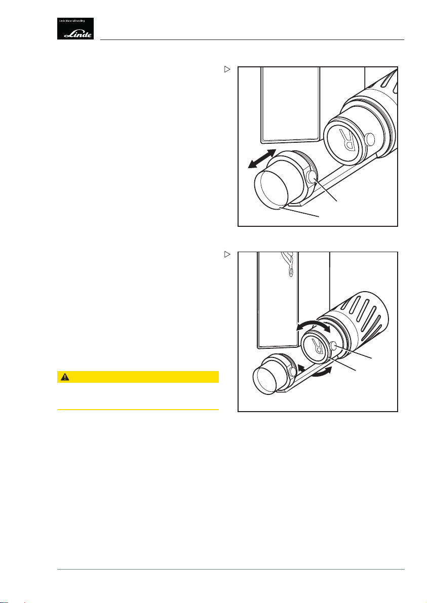
Inserting or replacing the gobo
Inserting or replacing the gobo
WARNING
Risk of burns due to hot sleeve.
Before working on the warning projector, discon-
nect the power supply.
Allow the warning projector to cool down.
Loosen the sleeve (1) by turning it in an
anticlockwise direction and remove it
carefully.
Loosen the knurled-head screw M4 (2).
Remove the gobo holder (3).
3
2
1
LWP_06
1. Separate the two p
by unscrewing them i
direction.
2. Insert or replace the gobo so that the
image is back-to-front.
3. Screw together the two parts of the gobo
holder in a clockwise direction.
CAUTION
Damage to the goboafter inserting the gobo holder.
Do not tighten the knurled-head screw too securely.
Re-insert the gobo holder and carefully
tighten the knurled-head screw until the
gobo holder is secured in place.
arts of the gobo holder
n an anti-clockwise
1.
2.
3.
LWP_07
12 Operating Instructions – 3008011680 EN – 06/2018
Page 17
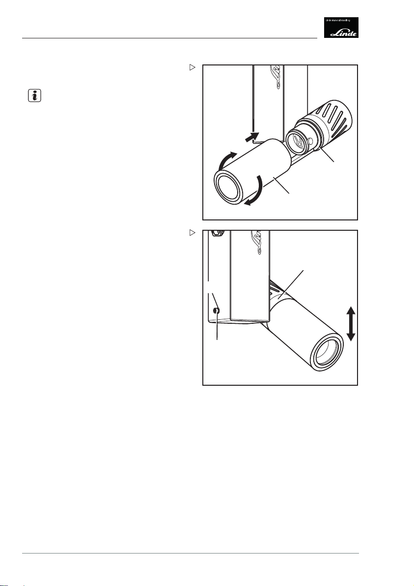
Focusing the warning pictogram
Loosen the sleeve in an anticlockwise
direction and remove it carefully.
Switch on the device.
Loosen the knurled-head s
Move the lens (2) until the warning pic-
togram is in focus.
Tighten the knurled-head screw.
crew M4 (1).
Aligning the warning pictogram
Loosen the sleeve in an anticlockwise
direction and remove it carefully.
Switch on the device.
Loosen the knu
Move the warning pictogram into the
required position by turning the gobo holder
(2).
CAUTION
Damage to the gobo.
Do not tighten the knurled-head screw too securely.
Carefully tighten the knurled-head screw
until the gobo holder is secured in place.
rled-head screw M4 (1).
Operation
Focusing the warning pictogram
1
2
LWP_08
1
2
LWP_09
4
Operating Instructions – 3008011680 EN – 06/2018 13
Page 18
Operation
4
Aligning the warning pictogram
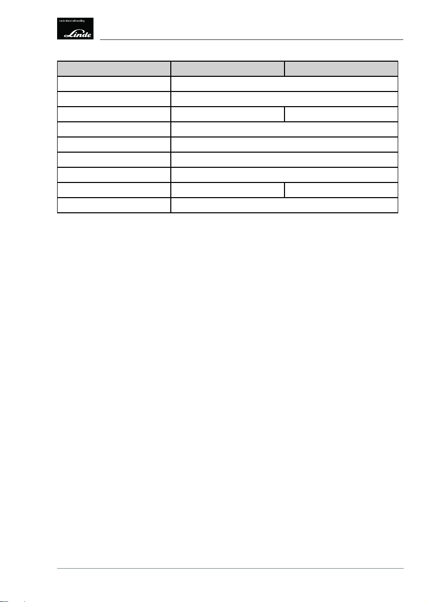
Check that the sealing ring (1) is correctly
positioned. Replace if necessary.
NOTE
The sealing faces and the sealing ring must
not be greased. Missing or defective sealing
rings must be replaced.
Carefully slide up the sleeve (2) and tighten
to 6.0...8.0 Nm to ensure leak tightness.
1
2
LWP_10
Perform the follo
the projector hea
Loosen the screw (2).
Align the projector head in the required
direction.
Tighten the scr
wing steps to vertically align
d(1):
ew to 3.0-4.0 Nm.
3
2
1 Projecto
2Socke
3Spring
r head
t head screw M6x16 mm
lock washer M6 and washer M6
1
LWP_11
14 Operating Instructions – 3008011680 EN – 06/2018
Page 19

5
Technical data
Page 20

5
Technical data
Dimensions
Dimensions
106 mm
205 mm
Technical data
85 mm
344 mm
482 mm
287 mm
LWP_12_1
Linde Warnprojektor 45 Linde Warnprojektor 85
Illuminant
Output power
Luminous flux
Colour temperature
Average LED service life (L70)
Projection
ambient ligh
distance in normal
ting
Projection distance in darkness
Image size
Photobiological safety
classification
1
High-power LED High-power LED
40 W 80 W
2700 lm 5750 lm
6300...6700 K
35,000 hours
4m 8m
10 m 20 m
∅50.0mm/∅40.0mm
DIN EN 62471 RG 2
Protection class I
Fanprotectiontype
1
After the specified service life, the LED still achieves 70% of the output luminous flux.
16 Operating Instructions – 3008011680 EN – 06/2018
IP 54
Page 21
Technical data 5
Technical data
Housing protection type
Input voltage
Power consumption
Linde Warnprojektor 45
110...240 V AC, 50/60 Hz
43 W 85 W
Linde Warnprojektor 85
IP 5x
Efficiency 0.93 cos. φ
Ambient temperature
-30 C...+35°C
Noise level 25 dBA
Dimensions (W x H x D)
344 x 287 x 205 mm
Weight 3.8 kg 4.0 kg
Material
.
Aluminium, steel
Operating Instructions – 3008011680 EN – 06/2018 17
Page 22

5
Technical data
Technical data
18 Operating Instructions – 3008011680 EN – 06/2018
Page 23

Page 24

Linde Material Handling GmbH
8011680 EN – 06/2018
300
Page 25

Projecteur d'avertissement
Linde
otice d'instructions
N
iginale
or
3008011680 FR – 06/2018
Page 26

Page 27

Table des matières
1 Introduction
Projecteur d'avertissement Linde ........................................ 2
Symboles utilisés .................................................... 2
Coordonnées de contact .............................................. 3
2 Vue d'ensemble
Vue d'ensemble des composants ........................................ 6
3 Montage
Assemblage du projecteu
Taille de projection ................................................... 9
r d'avertissement Linde ............................ 8
4 Fonctionnement
Insertion ou remplacement du gobo ...................................... 12
Mise au point du picto
Alignement du pictogramme d'avertissement ............................... 13
gramme d'avertissement .............................. 13
5 Données techniques
Dimensions ........................................................ 16
Données techniqu
es ................................................. 16
g
Notice d'instructions – 3008011680 FR – 06/2018 I
Page 28

Page 29

1
Introduction
Page 30

1 Introduction
Projecteur d'avertissement Linde
Projecteur d'avertissement Linde
Description de l'utilisation
Le projecteur d'avertissement Linde est
un projecteur à LED puissant et compact
permettant de projeter des pictogrammes
d'avertissement.
La projection de pictogram
ment garantit une visibili
nente, aidant ainsi à perce
Les avertissements sont af
nence, quelles que soient l
letés. Les coûts d'entreti
sécurité est accrue.
Les pictogrammes d'avertissement sont également bien visibles dans des environnements
de travail à faibles niveaux d'éclairage.
Une sélection de « gobos » (graphical optical
blackouts) peut être utilisée avec le projecteur,
ce qui permet une adaptation individuelle aux
conditions ambiantes et à une application
particulière.
Pour plus de sécurité au
meilleure protection d
vailleurs, le projecte
peut être combiné à l'e
ment statique Linde Sa
jecteur d'avertissem
mes d'avertisse-
té claire et perma-
voir les dangers.
fichés en perma-
'usure et les sa-
en sont réduits. La
travail et une
elasantédestra-
ur d'avertissement Linde
nsemble d'avertisse-
fety Guard. Le pro-
ent peut ainsi être mis en
tension lorsqu'un chariot de manutention approche.
Utilisation conforme
Le projecteur d'avertissement Linde est exclusivement utilisé pour projeter des pictogrammes d'avertissement.
Le projecteur d'avertisse
une utilisation en intérie
nements industriels. Il pe
fond, sur les murs ou sur des
Les projections ne dispensent pas les conducteurs de chariots de manutention et les piétons
de leur obligation légale de veiller à éviter les
situations potentiellement dangereuses.
Danger de lésions oculaires !
Ne pas directement regarder vers le
projecteur d'avertissement Linde.
Le projecteur d'avertissement Linde est
affectéàlaclassederisque2conformément
à DIN EN 62471.
ment est adapté à
ur dans des environ-
ut être fixé au pla-
montants.
PRUDENCE
Symboles utilisés
DANGER
Le non-respect des symboles peut impliquer des
blessures mortelles et/ou être à l'origine de dégâts
matériels importants.
PRUDENCE
Le non-respect des symboles peut impliquer des
blessuresgraveset/ouêtreàl'originededégâts
matériels importants.
2 Notice d'instructions – 3008011680 FR – 06/2018
ATTENTION
Le non-respect des symboles peut entraîner des
dégâts ou la destruction du matériau.
REMARQUE
Explication de contexte technique pouvant ne
pas être évident même pour un spécialiste.
Page 31

Coordonnées de contact
Fabricant
Derksen Lichttechnik GmbH
Johannes-Rau-Allee 4
45889 Gelsenkirchen, Allemagne
Téléphone : +49 (0) 209 98070-0
Fax : +49 (0) 209 98070-60
E-mail : info@derksen.de
Site Internet : https://www.derksen.de/en/
Introduction 1
Coordonnées de contact
Ventes et service par :
Linde Material Handling GmbH
Carl-von-Linde-Platz
63743 Aschaffenburg, Allemagne
Téléphone : +49 (0) 6021 99-0
Fax : +49 (0) 6021 99-1570
E-mail : info@linde-mh.de
Site Internet : http://www.linde-mh.de
Notice d'instructions – 3008011680 FR – 06/2018 3
Page 32

1 Introduction
Coordonnées de contact
4 Notice d'instructions – 3008011680 FR – 06/2018
Page 33

2
Vue d'ensemble
Page 34

2 Vue d'ensemble
Vue d'ensemble des composants
Vue d'ensemble des composants
9
8
1
2
7
3
4
5
6
1Carter
2 Douille
3 Têtedeprojecteur
4 Bague d'étanchéité
5 Porte-gobo
6 Notice d'instructions – 3008011680 FR – 06/2018
6 Support de lentille
7 Lentille
8 Plaque de fixation
9 Douille pour l'alimentation en tension
LWP_13
Page 35

3
Montage
Page 36

Montage
3
Assemblage du projecteur d'avertissement Linde
Assemblage du projecteur
d'avertissement Linde
PRUDENCE
Risque de blessures en raison d'une mauvaise
fixation.
Monter le projecteur d'avertissement sur des
constructions qui peuvent supporter quatre fois
le poids du dispositif.
Utiliser des matériaux de fixation adaptés.
Dévisser les quatre vis (1) avec les ron-
delles élastiques (2) et libérer la plaque de
fixation (3).
Retirer la plaque de fixation.
Fixerlaplaquedefixationàl'emplacement
requis. Pour ce faire, utiliser le matériel de
fixation approprié.
Insérer le projecteur d'avertissement dans
la plaque de fixation (1) et le fixer avec
quatre vis (2) et rondelles élastiques (3).
Couple de serrage : 3,0...4,5 Nm
3
1 Vis chc M6x20 mm
2 Rondelle élastique M6
3 Plaque de fixation
1
1
2
LWP_03
2
3
LWP_04
8 Notice d'instructions – 3008011680 FR – 06/2018
Page 37

Etablir une connexion électrique entre le
projecteur et la douille (2) à l'aide du câble
fourni (1).
Le dispositif est prêt à l'emp
loi.
Montage
3
Taille de projection
2
REMARQUE
Par défaut, le projecteur d'avertissement
Linde fonctionne en continu. Il ne peut être
allumé et éteint en connectant/déconnectant
l'alimentation en tension.
Taille de projection
La taille de projection du pictogramme d'avertissement dépend de la distance entre le projecteur d'avertissement et la surface de projection. La puissance de sortie de la LED et
l'éclairage ambiant augmentent ou diminuent
la distance à laquelle l'image est toujours clairement visible.
Les tailles de projectionsuivantes s'appliquent
à une distance de projection de 10 m pour les
deux puissances de sortie :
Distance
1m
2m
3m
4m
5m
6m
7m
8m
9m
10 m
1
LWP_05
Taille de projection
0,3 m
0,6 m
0,9 m
1,2 m
1,4 m
1,7 m
2,0 m
2,3 m
2,6 m
2,9 m
Notice d'instructions – 3008011680 FR – 06/2018 9
Page 38

Montage
3
Taille de projection
La taille de projection se réfère à une image
circulaire. D'autres formes sont réglées pour
être contenues au sein de ce cercle.
10 Notice d'instructions – 3008011680 FR – 06/2018
Page 39

4
Fonctionnement
Page 40

4 Fonctionnement
Insertion ou remplacement du gobo
Insertion ou remplacement du
gobo
PRUDENCE
Risque de brûlures dû à une douille chaude.
Avant de travailler sur le projecteur d'avertisse-
ment, débrancher l'alimentation en tension.
Laisser le projecteur d'avertissement refroidir.
Desserrer la douille (1) en la faisant tourner
dans le sens antihoraire et la retirer avec
précaution.
Desserrer les deux vis à tête moletée M4
(2).
Retirer le porte-gobo (3).
1. Séparer les deux parties du porte-gobo
en les dévissant dans le sens antihoraire.
2. Insérer ou remplacer le gobo afin que
l'image soit dans les deux sens.
3. Visser les deux parties du porte-gobo
dans le sens horaire.
ATTENTION
Le gobo peut êtr
porte-gobo.
Ne pas serrer la v
e endommagé après l'insertion du
is à tête moletée trop fortement.
3
2
1
LWP_06
1.
2.
Insérer de nouve
avec précaution
cequeleporte-g
12 Notice d'instructions – 3008011680 FR – 06/2018
au le porte-gobo et serrer
la vis à tête moletée jusqu'à
obo soit fixé.
3.
LWP_07
Page 41

Mise au point du pictogramme d'avertissement
Desserrer la douille dans le sens antihoraire
et la retirer avec précaution.
Allumer le dispositif.
Desserrer les deux vis à tê
(1).
Déplacer la lentille (2) jusqu'à ce que le
pictogramme d'avertissement soit net.
Serrer la vis à tête moletée.
te moletée M4
Alignement du pictogramme d'avertissement
Desserrer la douille dans le sens antihoraire
et la retirer avec précaution.
Allumer le dispositif.
Desserrer les
(1).
Déplacer le pictogramme d'avertissement
sur la position requise en tournant le
porte-gobo (2).
ATTENTION
Le gobo peut être endommagé.
Ne pas serrer la vis à tête moletée trop fortement.
deux vis à tête moletée M4
Fonctionnement 4
Mise au point du pictogramme d'avertissement
1
2
LWP_08
1
2
LWP_09
Serrer soigneusement la vis à tête moletée
jusqu'à ce que le porte-gobo soit fixé.
Notice d'instructions – 3008011680 FR – 06/2018 13
Page 42

4 Fonctionnement
Alignement du pictogramme d'avertissement
Vérifier le bon positionnement de la bague
d'étanchéité (1). Les remplacer si nécessaire.
REMARQUE
Les surfaces d'étanchéité et la bague d'étanchéité ne doivent pas être graissées. Les
bagues d'étanchéité manquantes ou défectueuses doivent être remplacées.
Faire délicatement glisser la douille vers
le haut (2) et serrer à 6,0...8,0 Nm pour
assurer l'étanchéité.
1
2
LWP_10
Effectuer les opéra
aligner verticalem
tions suivantes pour
ent la tête de projecteur
(1) :
Desserrer la vis (2).
Aligner la tête de projecteur dans le sens
requis.
Serrer la vis à un c
ouplede3,0à4,0Nm.
3
2
1Têtedepr
2Visch
3 Rondel
ojecteur
c M6x16 mm
le Grower M6 et rondelle M6
1
LWP_11
14 Notice d'instructions – 3008011680 FR – 06/2018
Page 43

5
Données techniques
Page 44

Données techniques
5
Dimensions
Dimensions
106 mm
205 mm
85 mm
344 mm
482 mm
287 mm
LWP_12_1
Données techniques
Linde Warnprojektor 45 Linde Warnprojektor 85
Illuminant
Puissance de sortie 40 W 80 W
Flux lumineux 2 700 lm 5 750 lm
Température de couleur
Durée de vie moyenne de la
LED (L70)
1
Distance de projection dans
des conditions normales
d'éclairage ambiant
Distance de projection dans
l'obscurité
Taille de l'image
Classification de sécurité
photobiologique
1
Après la durée de vie spécifiée, la LED dispense encore 70 % du flux lumineux de sortie.
16 Notice d'instructions – 3008011680 FR – 06/2018
LED haute puissance LED haute puissance
6 300...6 700 K
35 000 heures
4m 8m
10 m 20 m
∅50,0mm/∅40,0mm
DIN EN 62471 RG 2
Page 45

Données techniques
Données techniques
5
Linde Warnprojektor 45
Classe de protection
Type de protection du
ventilateur
Type de protection du carter
Tension d'entrée
Consommation électriqu
e
Rendement
Température ambiante
110...240 V CA, 50/60 Hz
43 W 85 W
I
IP 54
IP 5x
0,93 cos. φ
-30 °C...+35 °C
Niveau sonore 25 dBA
Dimensions (l x H x P)
Poids
Matériel
.
344 x 287 x 205 mm
3,8 kg 4,0 kg
Aluminium, acier
Linde Warnprojektor 85
Notice d'instructions – 3008011680 FR – 06/2018 17
Page 46

Données techniques
5
Données techniques
18 Notice d'instructions – 3008011680 FR – 06/2018
Page 47

Page 48

Linde Material Handling GmbH
8011680 FR – 06/2018
300
Page 49

Linde Warnprojektor
riginalbetriebsanleitung
O
3008011680 DE – 06/2018
Page 50

Page 51

Inhaltsverzeichnis
1 Einführung
Linde Warnprojektor ................................................. 2
Verwendete Symbole ................................................. 2
Kontaktdaten ....................................................... 3
2 Übersicht
Komponentenübersicht ............................................... 6
3 Montage
Linde Warnprojektor mon
Projektionsgröße .................................................... 9
tieren ......................................... 8
4 Bedienung
Gobo einsetzen oder wechseln .......................................... 12
Warnpiktogramm scha
Warnpiktogramm ausrichten ........................................... 13
rfstellen .......................................... 13
5 Technische Daten
Abmessungen ...................................................... 16
Technische Daten
................................................... 16
g
Betriebsanleitung – 3008011680 DE – 06/2018 I
Page 52

Page 53

1
Einführung
Page 54

Einführung
1
Linde Warnprojektor
Linde Warnprojektor
Einsatzbeschreibung
Der Linde Warnprojektor ist ein kompakter
Hochleistungs-LED Strahler zur Projektion
von Warnpiktogrammen.
Das Projizieren der Warnpi
währleistet eine klare und
barkeit und unterstützt da
mung von Gefahren. Unabhän
schleiß und Schmutz sind di
dauerhaft sichtbar. Wartu
reduziert. Die Sicherheit
Warnpiktogramme sind auch in schwach beleuchteten Arbeitsumgebungen gut sichtbar.
Eine Auswahl an „Gobos“ (Graphical optical
blackout) ermöglicht dabei die individuelle
Abstimmung auf die Umgebungsbedingungen
und die jeweilige Einsatzsituation.
Um die Arbeitssicherhei
kann der Linde Warnproj
statischen Warneinric
Guard gekoppelt werden
der Warnprojektor bei A
Flurförderzeugs einge
ktogramme ge-
dauerhafte Sicht-
mit die Wahrneh-
gig von Ver-
e Warnungen
ngskosten werden
wird erhöht.
t weiter zu steigern,
ektor z. B. mit der
htung Linde Safety
. Dadurch kann
nnäherung eines
schaltet werden.
Bestimmungsgemäße Verwendung
Der Linde Warnprojektor dient ausschließlich
zur Projektion von Warnpiktogrammen.
Der Warnprojektor ist für den
industriellen Innenräume
an der Decke, an Wänden oder
angebracht.
Die Projektionen entbinden die Fahrer von
Flurförderzeugen und Fußgänger nicht von
ihrer gesetzlichen Sorgfaltspflicht, mögliche
Gefahrensituationen zu vermeiden.
VORSICHT
Schädigung der Augen!
Nicht direkt in den Linde Warnprojek-
tor hineinschauen.
Der Linde Warnprojektor ist gemäß
DIN EN 62471 der Risikogruppe 2 zugeordnet.
Einsatz in
n geeignet. Er wird
an Streben
Verwendete Symbole
GEFAHR
Bei Nichtbeachtung besteht Lebensgefahr
und/oder die Gefahr erheblicher Sachschäden.
VORSICHT
Bei Nichtbeachtung besteht die Gefahr schwerer
Verletzungen und/oder erheblicher Sachschäden
2 Betriebsanleitung – 3008011680 DE – 06/2018
ACHTUNG
Bei Nichtbeachtung bestehtdie gefahr von Beschädigung oder Zerstörung des Materials.
HINWEIS
Erklärung technischer Zusammenhänge, die
auch für Fachkräfte nicht offensichtlich sind.
Page 55

Kontaktdaten
Hersteller
Derksen Lichttechnik GmbH
Johannes-Rau-Allee 4
45889 Gelsenkirchen
Telefon: +49 (0) 209 98070-0
Telefax: +49 (0) 209 98070-60
E-Mail: info@derksen.de
Website: http://www.derksen.de
Einführung
Vertrieb und Service über:
Linde Material Handling GmbH
Carl-von-Linde-Platz
63743 Aschaffenburg
Telefon +49 (0) 6021 99-0
Telefax +49 (0) 6021 99-1570
E-Mail: info@linde-mh.de
Website: http://www.linde-mh.de
1
Kontaktdaten
Betriebsanleitung – 3008011680 DE – 06/2018 3
Page 56

Einführung
1
Kontaktdaten
4 Betriebsanleitung – 3008011680 DE – 06/2018
Page 57

2
Übersicht
Page 58

2 Übersicht
Komponentenübersicht
Komponentenübersicht
8
1
9
2
7
3
4
5
6
1 Gehäuse
2Hülse
3 Projektionskopf
4 Dichtring
5 Gobo-Halter
6 Betriebsanleitung – 3008011680 DE – 06/2018
6 Objektivhalter
7 Objektiv
8 Montageblech
9 Buchse für Spannungsversorgung
LWP_13
Page 59

3
Montage
Page 60

Montage
3
Linde Warnprojektor montieren
Linde Warnprojektor montieren
VORSICHT
Verletzungsgefahr durch unsichere Befestigung.
Warnprojektor an Konstruktionen befestigen, die
das 4-fache Gewicht des Geräts tragen können.
Geeignetes Befestigungsmaterial verwenden.
Vier Schrauben (1) mit Spannscheiben (2)
herausdrehen und Montageblech (3) lösen.
Montageblech abnehmen.
Montageblech an der gewünschten Stelle
befestigen. Dabei geeignete Befestigungsmaterialien verwenden.
Warnprojektor in das Montageblech (1)
einsetzen und mit vier Schrauben (2) und
Spannscheiben (3) befestigen.
Anzugsdrehmoment: 3,0...4,5 Nm
3
1 Zylinderkopfschraube M6x20 mm
2 Spannscheibe M6
3 Montageblech
1
1
2
LWP_03
2
3
LWP_04
8 Betriebsanleitung – 3008011680 DE – 06/2018
Page 61

Projektor mit beiliegendem Kabel (1) an der
Buchse (2) elektrisch anschließen.
Das Gerät kann verwendet werd
HINWEIS
en.
Der Linde Warnprojektor befindet sich standardmäßig im Dauerbetrieb. Ein- und Ausschalten ist nur über die Spannungsversorgung möglich.
Projektionsgröße
Die Projektionsgröße der Warnpiktogramme
ist abhängig von der Entfernung zwischen
dem Warnprojektor und der Projektionsfläche.
Die Ausgangsleistung der LED und die
Raumbeleuchtung erhöhen oder verringern
die Reichweite, in der das Motiv noch gut
sichtbar ist.
Bis zu einer Projektionsentfernung von 10 m
gelten die folgenden Projektionsgrößen für
beide Ausgangsleistungen:
Montage
3
Projektionsgröße
2
1
LWP_05
Entfernung Projektionsgröße
1m
2m
3m
4m
5m
6m
7m
8m
9m
10 m
Betriebsanleitung – 3008011680 DE – 06/2018 9
0,3 m
0,6 m
0,9 m
1,2 m
1,4 m
1,7 m
2,0 m
2,3 m
2,6 m
2,9 m
Page 62

Montage
3
Projektionsgröße
Die Projektionsgröße bezieht sich dabei auf
ein kreisrundes Abbild. Davon abweichende
Formen werden in diesen Kreis eingepasst.
10 Betriebsanleitung – 3008011680 DE – 06/2018
Page 63

4
Bedienung
Page 64

Bedienung
4
Gobo einsetzen oder wechseln
Gobo einsetzen oder
wechseln
VORSICHT
Verbrennungsgefahr durch heiße Hülse.
Vor Arbeiten am Warnprojektor Spannungsversor-
gung abziehen.
Warnprojektor abkühlen lassen.
Hülse (1) gegen den Uhrzeigersinn losdre-
hen und vorsichtig entfernen.
Rändelschraube M4 (2) lösen.
Gobo-Halter (3) entnehmen.
3
2
1
LWP_06
1. Gobo-Halter gege
auseinanderschrau
2. Gobo spiegelverkehrt einsetzen oder
wechseln.
3. Gobo-Halter im Uhrzeigersinn zusam-
menschrauben.
ACHTUNG
Beschädigung des Gobos nach Einsetzen des
Gobo-Halters.
Rändelschraube nicht zu fest anziehen.
Gobo-Halter wieder einsetzen und Rän-
delschraube vorsichtig festziehen bis der
Gobo-Halter fest sitzt.
n den Uhrzeigersinn
ben.
1.
2.
3.
LWP_07
12 Betriebsanleitung – 3008011680 DE – 06/2018
Page 65

Warnpiktogramm scharfstellen
Hülse gegen den Uhrzeigersinn losdrehen
und vorsichtig entfernen.
Gerät einschalten.
Rändelschraube M4 (1) lös
Objektiv (2) verschieben, bis das Warnpik-
togramm scharf ist.
Rändelschraube festziehen.
en.
Warnpiktogramm ausrichten
Hülse gegen den Uhrzeigersinn losdrehen
und vorsichtig entfernen.
Gerät einschalten.
Rändelschraub
Warnpiktogramm durch Drehen des Gobo-
Halters (2) in die gewünschte Position
bringen.
ACHTUNG
Beschädigung des Gobos.
Rändelschraube nicht zu fest anziehen.
e M4 (1) lösen.
Bedienung
Warnpiktogramm scharfstellen
1
2
LWP_08
1
2
4
Rändelschraube vorsichtig festziehen, bis
der Gobo-Halter fest sitzt.
Betriebsanleitung – 3008011680 DE – 06/2018 13
LWP_09
Page 66

Bedienung
4
Warnpiktogramm ausrichten
Dichtring (1) auf korrekten Sitz kontrollie-
ren. Gegebenenfalls wechseln.
HINWEIS
Dichtflächen und Dichtring dürfen nicht
gefettet werden. Fehlende oder defekte
Dichtringe müssen ersetzt werden.
Hülse (2) vorsichtig aufschieben und mit
6,0...8,0 Nm anziehen, um die Dichtigkeit
zu gewährleisten.
1
2
LWP_10
Zum Ausrich
vertikaler
durchführe
Schraube (2) lösen.
Projektionskopf in diegewünschte Richtung
ausrichten.
Schraube m
ten des Projektionskopfs (1) in
Richtung die folgenden Schritte
n:
it 3,0-4,0 Nm festziehen.
3
2
1 Projekti
2 Zylin
3Fed
onskopf
derkopfschraube M6x16 mm
errring M6 und Unterlegscheibe M6
1
LWP_11
14 Betriebsanleitung – 3008011680 DE – 06/2018
Page 67

5
Technische Daten
Page 68

5
Technische Daten
Abmessungen
Abmessungen
106 mm
205 mm
85 mm
344 mm
482 mm
287 mm
LWP_12_1
Technische Daten
Linde Warnprojektor 45 Linde Warnprojektor 85
Leuchtmittel
Ausgangsleistung
Lichtstrom 2700 lm 5750 lm
Farbtemperatur
LED-Lebensdauer
Mittlere
1
(L70)
Projektionsentfernung bei
normaler Raumbeleuchtung
Projektionsentfernung bei
Dunkelheit
Motivgröße
Klassifizierung photobiologische Sicherheit
Schutzklasse I
1
Nach angegebener Betriebsdauer erreicht die LED noch 70% des Ausgangslichtstroms.
16 Betriebsanleitung – 3008011680 DE – 06/2018
High Power LED High Power LED
40 W 80 W
6300...6700 K
35000 Stunden
4m 8m
1
0m
2
0m
∅ 50,0 mm / ∅ 40,0 mm
DIN EN 62471 RG 2
Page 69

Technische Daten 5
Technische Daten
Linde Warnprojektor 45
Schutzart Lüfter IP 54
Schutzart Gehäuse IP 5x
Eingangsspannung
Leistungsverbrauch
110...240 V AC, 50/60 Hz
43 W 85 W
Wirkungsgrad 0,93 cos. φ
Umgebungstemperatur
Geräuschpegel
Abmessungen (B x H x T)
Gewicht
Material
.
3,8 kg 4,0 kg
-30° C...+35 °C
25 dBA
344 x 287 x 205 mm
Aluminium, Stahl
Linde Warnprojektor 85
Betriebsanleitung – 3008011680 DE – 06/2018 17
Page 70

5
Technische Daten
Technische Daten
18 Betriebsanleitung – 3008011680 DE – 06/2018
Page 71

Page 72

Linde Material Handling GmbH
8011680 DE – 06/2018
300
Page 73

Proiettore per avvertenza
Linde
struzioni originali
I
3008011680 IT – 06/2018
Page 74

Page 75

1 Introduzione
Proiettore per avvertenza Linde ......................................... 2
Simboli utilizzati ..................................................... 2
Informazioni di contatto ............................................... 3
2 Panoramica
Panoramica dei componenti ............................................ 6
3 Montaggio
Assemblaggio del proiet
Dimensioni della proiezione ............................................ 9
tore per avvertenze Linde ........................... 8
4 Funzionamento
Inserimento o sostituzione del gobo ...................................... 12
Messa a fuoco del pitt
Allineamento del pittogramma di avvertenza ................................ 13
ogramma di avvertenza ............................... 13
5 Dati tecnici
Dimensioni ........................................................ 16
Dati tecnici ......................................................... 16
Indice
g
Manuale d'uso – 3008011680 IT – 06/2018 I
Page 76

Page 77

1
Introduzione
Page 78

1 Introduzione
Proiettore per avvertenza Linde
Proiettore per avvertenza Linde
Descrizione dell'uso
Il proiettore per avvertenze Linde è un faro a
LED potente e compatto per la proiezione di
pittogrammi di avvertenza.
La proiezione dei pittogra
garantisce una visibilità
e favorisce quindi la perce
Le avvertenze sono sempre v
dentemente dall'usura e da
di manutenzione sono ridot
maggiore.
I pittogrammi di avvertenza sono chiaramente
visibili anche in ambienti di lavoro con bassi
livelli di luminosità.
Con il proiettore è possibile utilizzare una
selezione di « gobo » (graphical optical
blackouts), che permettono l'adattamento
alle specifiche condizioni ambientali e alla
particolare applicazione.
Per aumentare ulterior
sicurezza sul lavoro, è
il proiettore Linde all
statica Linde Safety Gu
mmi di avvertenza
chiara e permanente
zione dei pericoli.
isibili, indipenlla sporcizia. I costi
ti. La sicurezza è
mente la salute e la
possibile associare
'unità di avvertimento
ard. In questo modo, il
proiettore può essere acceso all'avvicinarsi di
un carrello industriale.
Uso previsto
Il proiettore Linde viene utilizzato esclusivamente per proiettare pittogrammi di avvertenza.
Il proiettore è adatto per l
interni industriali. Può e
soffitto, a parete o su punto
Le proiezioni non dispensano i conducenti
di carrelli industriali e i pedoni dall'obbligo
giuridico di evitare situazioni potenzialmente
pericolose.
AVVERTIMENTO
Danni agli occhi!
Non guardare direttamente il proiet-
tore Linde.
Il proiettore Linde è assegnato al gruppo
di rischio 2 in conformità alla norma
DIN EN 62471.
'uso in ambienti
ssere montato a
ni.
Simboli utilizzati
PERICOLO
La mancata osservanza di questo simbolo potrebbe comportare lesioni mortali e/o gravi danni
all'attrezzatura.
AVVERTIMENTO
La mancata osservan
trebbe comportare
gravi.
2 Manuale d'uso – 3008011680 IT – 06/2018
za di questo simbolo po-
lesioni e/o danni all'attrezzatura
ATTENZIONE
La mancata osservanza di questo simbolo potrebbe provocare il danneggiamento o la distruzione del materiale.
NOTA
Spiegazione d
trebbe non risul
tecnico speci
el contesto tecnico che po-
tare evidente neppure a un
alizzato.
Page 79

Informazioni di contatto
Costruttore
Derksen Lichttechnik GmbH
Johannes-Rau-Allee 4
45889 Gelsenkirchen, Germania
Telefono: +49 (0) 209 98070-0
Fax: +49 (0) 209 98070-60
E-mail: info@derksen.de
Sito Web: https://www.derksen.de/en/
Introduzione 1
Informazioni di contatto
Vendita e assistenza:
Linde Material Handling GmbH
Carl-von-Linde-Platz
63743 Aschaffenburg, Germania
Telefono: +49 (0) 6021 99-0
Fax: +49 (0) 6021 99-1570
E-mail: info@linde-mh.de
Sito Web: http://www.linde-mh.de
Manuale d'uso – 3008011680 IT – 06/2018 3
Page 80

1 Introduzione
Informazioni di contatto
4 Manuale d'uso – 3008011680 IT – 06/2018
Page 81

2
Panoramica
Page 82

2 Panoramica
Panoramica dei componenti
Panoramica dei componenti
9
8
1
2
7
3
4
5
6
1 Alloggiamento
2 Manicotto
3 Testa proiettore
4 Anello di tenuta
5 Supporto per gobo
6 Manuale d'uso – 3008011680 IT – 06/2018
6 Supporto lente
7 Lente
8 Piastra di fissaggio
9 Presa per alimentazione
LWP_13
Page 83

3
Montaggio
Page 84

Montaggio
3
Assemblaggio del proiettore per avvertenze Linde
Assemblaggio del proiettore
per avvertenze Linde
AVVERTIMENTO
Rischio di lesioni in caso di fissaggio non sicuro.
Montare il proiettore per avvertenze su strutture
che possano sostenere quattro volte il peso del
dispositivo.
Utilizzare materiali di montaggio idonei.
Svitare le quattro viti (1) e le rondelle elasti-
che (2) e liberare la piastra di montaggio (3).
Rimuovere la piastra di montaggio.
Fissare la piastra di montaggio nella po-
sizione richiesta. Utilizzare materiali di
montaggio idonei per tale scopo.
Inserire il pro
taggio (1) e fiss
rondelle elas
Coppia di serraggio: 3,0...4,5 Nm
iettore nella piastra di mon-
arlo con quattro viti (2) e
tiche (3).
3
1 Vite a esagono cavo M6x20 mm
2 Rondella elastica M6
3 Piastra di fissaggio
1
1
2
LWP_03
2
3
LWP_04
8 Manuale d'uso – 3008011680 IT – 06/2018
Page 85

Effettuare il collegamento elettrico tra
il proiettore e la presa (2) con il cavo in
dotazione (1).
Il dispositivo è pronto per l'
uso.
Dimensioni della proiezione
2
Montaggio
3
NOTA
Per impostazione predefinita, il proiettore per
avvertenze Linde funziona senza interruzioni.
È possibile accenderlo e spegnerlo solo
collegando/scollegando l'alimentazione.
Dimensioni della proiezione
Le dimensioni della proiezione del pittogramma di avvertenza variano in base alla
distanza tra il proiettore e la superficie di proiezione. La potenza di emissione del LED e
l'illuminazione dell'ambiente aumentano o diminuiscono la distanza a cui l'immagine risulta
chiaramente visibile.
Le dimensioni della proiezione seguenti si
riferiscono a una distanza di proiezione di
10 m per entrambe le potenze in uscita:
Distanza
1m
2m
3m
4m
5m
6m
7m
8m
9m
10 m
1
Dimensioni dell
LWP_05
a proiezione
0,3 m
0,6 m
0,9 m
1,2 m
1,4 m
1,7 m
2,0 m
2,3 m
2,6 m
2,9 m
Manuale d'uso – 3008011680 IT – 06/2018 9
Page 86

Montaggio
3
Dimensioni della proiezione
La dimensione della proiezione si riferisce a
un'immagine circolare. Altre forme vengono
regolate in modo da entrare in questo cerchio.
10 Manuale d'uso – 3008011680 IT – 06/2018
Page 87

4
Funzionamento
Page 88

4 Funzionamento
Inserimento o sostituzione del gobo
Inserimento o sostituzione del
gobo
AVVERTIMENTO
Rischio di ustioni dovuto a superfici calde.
Prima di intervenire sul proiettore, scollegare
l'alimentazione.
Lasciare che il proiettore si raffreddi.
Allentare il manicotto (1) ruotandolo in
senso antiorario e rimuoverlo con cautela.
AllentarelaviteatestazigrinataM4(2).
Rimuovere il supporto per gobo (3).
3
2
1
LWP_06
1. Separare le due pa
gobo svitandole in s
2. Inserire o sostituire il gobo in modo che
l'immagine abbia il retro rivolto in avanti.
3. Avvitare insieme le due parti del supporto
per gobo in senso orario.
ATTENZIONE
Danneggiamento del gobo dopo l'inserimento nel
relativo supporto.
Non serrare eccessivamente la vite a testa zigrinata.
Inserire nuovamente il supporto per gobo e
serrare con cautela la vite a testa zigrinata
fino a quando il supporto per gobo è fissato
in posizione.
rti del supporto per
enso antiorario.
1.
2.
3.
LWP_07
12 Manuale d'uso – 3008011680 IT – 06/2018
Page 89

Messa a fuoco del pittogramma di avvertenza
Allentare il manicotto ruotandolo in senso
antiorario e rimuoverlo con cautela.
Accendere il dispositivo.
Allentarelaviteatestaz
Spostare la lente (2) fino a quando il pitto-
gramma di avvertenza è a fuoco.
Serrarelaviteatestazigrinata.
igrinata M4 (1).
Allineamento del pittogramma di avvertenza
Allentare il manicotto ruotandolo in senso
antiorario e rimuoverlo con cautela.
Accendere il dispositivo.
Allentare la v
Spostare il pittogramma di avvertenza nella
posizione desiderata ruotando il supporto
per gobo (2).
ATTENZIONE
Danneggiamento del gobo.
Non serrare eccessivamente la vite a testa zigri-
nata.
ite a testa zigrinata M4 (1).
Funzionamento 4
Messa a fuoco del pittogramma di avvertenza
1
2
LWP_08
1
2
LWP_09
Serrareconcautelalaviteatestazigrinata
fino a quando il supporto per gobo è fissato
in posizione.
Manuale d'uso – 3008011680 IT – 06/2018 13
Page 90

4 Funzionamento
Allineamento del pittogramma di avvertenza
Controllare che l'anello di tenuta (1) sia
posizionato correttamente. Se necessario,
sostituire.
NOTA
Sulle superfici di tenuta e sull'anello di tenuta
non deve essere presente del grasso. Montare eventuali anelli di tenuta mancanti o sostituire se danneggiati.
Far scorrere con cautela il manicotto (2)
e serrare a 6,0...8,0 Nm per garantire la
tenuta.
Attenersi alla procedura seguente per allineare verticalmente la testa del proiettore (1):
Allentare la v
Allineare la testa del proiettore nella dire-
zione desiderata.
Serrarelavitea3,0-4,0Nm.
ite (2).
1
2
LWP_10
1
3
2
LWP_11
1Testapro
2Vitea
3Ro
14 Manuale d'uso – 3008011680 IT – 06/2018
iettore
esagono cavo M6x16 mm
ndella elastica M6 e rondella M6
Page 91

5
Dati tecnici
Page 92

5
Dati tecnici
Dimensioni
Dimensioni
106 mm
205 mm
Dati tecnici
85 mm
344 mm
482 mm
287 mm
LWP_12_1
Linde Warnprojektor 45 Linde Warnprojektor 85
Illuminazione
LED ad alta potenza LED ad alta potenza
Potenza in uscita 40 W 80 W
Potenza luminosa 2700 lm 5750 lm
Temperatura colore
Durata media del LED (L70)
Distanza d
ambient
i proiezione in
e con illuminazione
1
4m 8m
6300...6700 K
35.000 ore
normale
Distanza di proiezione al buio
Dimensione dell'immagine
cazione fotobiologica di
Classifi
za
sicurez
Classe di protezione
1
Dopo la durata specificata, il LED continua a erogare il 70% della potenza luminosa.
16 Manuale d'uso – 3008011680 IT – 06/2018
10 m 20 m
∅50,0mm/∅40,0mm
DINEN6
2471 RG 2
I
Page 93

Dati tecnici 5
Dati tecnici
Indice di protezione ventola
Indice di protezione alloggia-
mento
Tensione in ingresso
Consumo di alimentazione
Efficienza
Temperatura ambiente
Livello di rumorosità
Dimensioni (L x A x P)
Peso
Materiale
.
Linde Warnprojektor 45
110...240 V CA, 50/60 Hz
43 W 85 W
0,93 cos. φ
-30 C...+35°C
344 x 287 x 205 mm
3,8 kg 4,0 kg
Alluminio, acciaio
Linde Warnprojektor 85
IP 54
IP 5x
25 dBA
Manuale d'uso – 3008011680 IT – 06/2018 17
Page 94

5
Dati tecnici
Dati tecnici
18 Manuale d'uso – 3008011680 IT – 06/2018
Page 95

Page 96

Linde Material Handling GmbH
8011680 IT – 06/2018
300
Page 97

Proyector de advertencia
Linde
anual original
M
3008011680 ES – 06/2018
Page 98

Page 99

Tabladematerias
1 Introducción
Proyector de advertencia Linde ......................................... 2
Símbolos usados .................................................... 2
Datos de contacto ................................................... 3
2 Descripción general
Descripción general de los componentes .................................. 6
3 Montaje
Montaje del proyector de
Tamaño de proyección ................................................ 9
advertencia Linde ................................ 8
4 Funcionamiento
Engaste o sustitución del gobo .......................................... 12
Centrado del pictogr
Alineación del pictograma de advertencia .................................. 13
ama de advertencia ................................... 13
5 Datos técnicos
Dimensiones ....................................................... 16
Datos técnicos ...................................................... 16
g
Instrucciones de manejo – 3008011680 ES – 06/2018 I
Page 100

 Loading...