

Lift-master SL505 User Manual

OWNER'S MANUAL
MODEL SL505
RESIDENTIAL SLIDE GATE OPERATORS
SL505 GATE OPERATORS ARE FOR USE ON VEHICULAR PASSAGES
ONLY AND NOT INTENDED FOR USE ON PEDESTRIAN PASSAGE GATES.
2 YEAR WARRANTY
Serial # _____________________
(located on electrical box cover)
Installation Date:_______________
1

Contents
General Information...........................................................................................................3-4
Features...............................................................................................................................5-6
Parts Identification..............................................................................................................7-8
Installation.........................................................................................................................9-11
Electrical..........................................................................................................................12-16
Fine Tuning.......................................................................................................................16
Page
Master/Second........................................................................................................................17
Wiring Diagrams..............................................................................................................18-20
Safety Edge and Safety Warning Placard Installation....................................................21
Options............................................................................................................................22,23
Maintenance & Safety........................................................................................................24
Troubleshooting...............................................................................................................25-27
Notes......................................................................................................................................28, 29
IMPORTANT SAFETY INSTRUCTIONS
WARNING - To reduce the risk of injury or death:
1) READ AND FOLLOW ALL INSTRUCTIONS
2) Never let children operate or play with gate controls. Keep the remote control away from children.
3) Always keep people and objects away from the gate. NO ONE SHOULD CROSS THE PATH OF THE MOVING GATE.
4) Test the gate operator monthly. The gate MUST reverse on contact with a rigid object or stop when an object activates the non-contact sensors.
After adjusting the force or the limit of travel, re-test the gate operator. Failure to adjust and re-test the gate operator properly can increase the risk of
injury or death.
5) Use the emergency release only when the gate is not moving.
6) KEEP GATES PROPERLY MAINTAINED. Read the owner's manual. Have a qualified service person make repairs to gate hardware.
7) The entrance is for vehicles only. Pedestrians must use separate entrance.
8) SAVE THESE INSTRUCTIONS.
2
General Information
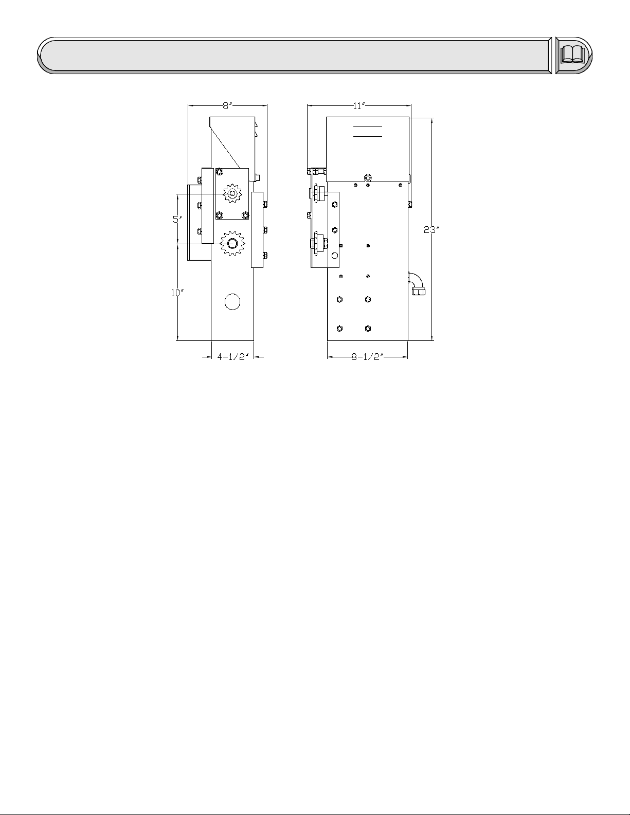
Overall Dimensions: Height: 23" Length: 11" Width: 8"
Shipping Weight: OPERATOR:53 lbs CHAIN PACKAGE:12 lbs MOUNTING POSTS:16 lbs
TOTAL: 81 lbs
Options: OPERATOR + BATTERY RUN PACKAGE: 59 lbs
LOW VOLTAGE CABLE: 1 lbs/10 ft
CONCRETE MOUNTING STAND: 17 lbs
Applications:
z MAXIMUM GATE WEIGHT: 375 lbs
z MAXIMUM GATE LENGTH: 20 ft
POWER REQUIREMENT: Dedicated 115 VAC (+/- 10V) , 5A Power Circuit
NOTE: For standard operator, place 115 VAC at or near the operator.
For Battery Run operator, place 115 VAC within 1,000 ft of the operator.
There are three possibilities for supplying power to the SL 505 gate operator. The standard power supply version is
made to connect directly to 115 Volt, 5 Amp power source and is available for full systems capability models. This power
supply must be at or near the gate operator location. Because of the low current draw, 115 Volt power may be run as far as
1000 feet with 12 gauge wire from the main breaker panel and can be run much farther with larger wire. Another possibility for
supplying power to the operator is with the low voltage battery run version of the SL 505. To supply power to the SL 505
battery run, wire as small as 16 gauge can be run as far as 300 feet from a charger that is plugged in remotely. Because the
power is low 12 Volt DC, the wire can be direct burial wire which eliminates the need for expensive conduit runs. The other
possibility for supplying power to the SL 505 is with the Solar power version of the operator. The Solar model does not require
any power to be run because the operator and solar power supply are self contained. The panel may be placed several
hundred feet from the operator if this is necessary to achieve maximum sunlight conditions.
3

General Information
INCLUDED WITH OPERATOR:
Check package to make sure it contains the following items.
STANDARD GATE OPENER
z 1-Model SL 505 gate operator
z 2-Mounting Posts 2" Diameter x 30"
z 2-Gate/Chain Brackets, U-Bolt type
z 2-U-Bolts Round
z 2-U-Bolts Square
z 1-Chain #40 x 25 ft
z 2-Master Links #40
z 2-Chain Bolts
z 2-Self Tapping Screws
z 1-Hex Key for Cover
z 2-Manual Release Keys
z 2-Safety Warning Placards
Vehicular Gate Operator Classes:
Class I - Residential Vehicular Gate Operator: A vehicular gate operator (or system) intended for use in a home of
one-to four single family dwellings, or a garage or parking area associated therewith.
Class II - Commercial/General Access Vehicular Gate Operator: A vehicular gate operator (or system) intended for
use in a commercial location or building such as a multi-family housing unit (five or more single family
units), hotel, garage, retail store, or other building servicing the general public.
Class III - Industrial/Limited Access Vehicular Gate Operator: A vehicular gate operator (or system) intended for use
in an industrial location or building such as a factory or loading dock area or other locations not intended
to service the general public.
Class IV - Restricted Access Vehicular Gate Operator: A vehicular gate operator (or system) intended for use in a
guarded industrial location or building such as an airport security area or other restricted access location
not servicing the general public, in which unauthorized access is prevented via supervision by security
personnel.
Gate Operator model SL 505 is intended for Vehicular Gate Operator Classes I, II, III, and IV.
BATTERY RUN ONLY (OPTIONAL)
z 1-Burial cable, 10 ft
z 1-Charger, 12 Volt
z 1-Battery, 12 Volt (installed)
SOLAR ONLY (OPTIONAL)
z 3-Pipe sections, 1" X 24"
z 2-Pipe couplings, 1"
z 1-Solar Panel Assembly
z 5-Lock Rings
z 2-Batteries, 12 Volt (installed)
(See parts identification.)
Gate Inspection:
a) Install the gate operator only when:
1) The operator is appropriate for the construction of the gate and the usage Class of the gate,
2) All openings of a horizontal slide gate are guarded or screened from the bottom of the gate to a minimum
of 4 feet (1.2 m) above the ground to prevent a 2-1/4 inch (57.15 mm) diameter sphere from passing
through the openings anywhere in the gate, and in that portion of the adjacent fence that the gate
covers in the open position.
3) All exposed pinch points are eliminated or guarded, and
4) Guarding is supplied for exposed rollers.
b) The operator is intended for installation only on gates used for vehicles. Pedestrians must be supplied with a
separate access opening.
c) The gate must be installed in a location so that enough clearance is supplied between the gate and adjacent
structures then opening and closing to reduce the risk of entrapment.
d) The gate must be properly installed and work freely in both directions prior to the installation of the gate operator.
Do not over-adjust the gate sensitivity to compensate for a damaged gate.
Mounting:
There are two ways to mount the SL 505 operator. One way to mount the operator is to attach it with bolts to a
concrete surface using the optional concrete mounting stand and sleeve anchors. In some cases there will already be an
existing concrete surface or pad available to bolt the operator to. If there is no existing concrete surface or pad, it is very
easy to fashion one so that the operator can be bolted down at a later time using sleeve anchors. The other way to mount
the SL 505 operator is directly into the earth with the two 2" X 30" mounting posts that have been provided. For this
installation the posts are attached to the operator, one post hole is made in the earth and then the operator with posts
attached is set in place. The cement can then be poured into the post hole and will dry within minutes if concrete accelerator
is used. The operator can be put into full operation the very same day.
4

Features
FULL SYSTEMS CAPABILITY
Sensitivity
As with other LiftMaster gate openers, the SL 505 has a built-in safety feature which when adjusted properly will
deliver only enough power to the motor to overcome the resistance of the gate. What this means is that if the gate runs into a
vehicle or pedestrian, the gate will immediately stop or reverse. Because of the DC motor technology incorporated into the
SL 505, the sensitivity feature is much more sensitive and is at least 50% more effective than traditional AC current sensors.
Soft Start/Soft Stop
A unique feature of the SL 505 is the Soft Start/Soft Stop feature. Traditional gate openers will begin opening the
gate with full power causing a yanking or jerking effect that severely decreases the life of mechanical parts. The SL 505 will
begin opening or closing the gate very slowly and will then increase to full speed. This creates a very gentle gate transition
which considerably reduces the amount of wear and tear on all mechanical parts.
Manual Release Key Switch
This simple on-off key switch is built into the side of the operator. In an emergency, even with the power off, the gate
can be pushed open manually after turning the key counter-clockwise.
Electronic Brake
Traditional gate openers typically have a mechanical brake or clutch which requires special maintenance. The DC
motor technology that is incorporated into the SL 505 provides the gate opener with a brake that will never wear out. This
patented feature causes the gate to come to a stop and keeps the gate locked when stopped in any position.
Battery Run/Low Voltage (Optional)
The SL 505 is available in both battery run and solar versions. The main and most obvious benefit to having battery
run or solar is the ability to open and close the gate even when there is no power. This in itself provides an extremely high
level of convenience. If there is a power failure the gate will operate as it normally does and can be opened up to 150 times
before power is restored. Another very important benefit to having battery run is that it is not necessary to have 115 Volts at
the operator location because running high voltage is typically very expensive and highly regulated. All that is needed to
supply power to a battery run version of the SL 505 is some inexpensive low voltage burial cable. If the cable is 16 gauge it
can be run as far as 300 feet. For solar versions of the SL 505, no power needs to be run to the operator. The solar version
has a solar panel which is normally attached to the gate opener but can placed anywhere that allows the panel to receive
maximum sunlight.
Visual Feedback
The SL 505 Full Systems Capability circuit board has been equipped with visual feedback LEDs (small indicator
lights) to help simplify installation and troubleshooting. There are LEDs located directly beside each input terminal to indicate
if any input devices are active. There are also two LEDs which indicate that the circuit board is delivering power to the motor
and are labeled O and C for either the Opening or Closing directions of travel respectively. Collectively, all of the LEDs
combined provide quick glance information to the installer or service technician showing visually what is happening in the
normally invisible operation of the circuit board.
5

Features continued...
Auto Close Timer
The operator comes factory preset with the auto close timer function OFF. The auto close timer will close the gate
automatically after a specific amount of time has elapsed. The amount of time can be easily adjusted between 0 and 45
seconds by turning a small "pot" located on the edge of the circuit board (See page 17). The timer can be disabled or
activated by flipping a single switch located on the top edge of the circuit board. If the timer will be used it is recommended
that some type of supplementary safety device (loops, photo beam etc.) be installed.
Gate Sensitivity Adjustment
The amount of force necessary to stop the gate can be adjusted to conform to the various sizes and weights of any
particular gate. The full systems capability circuit board provides separate adjustments for both the opening and closing
direction. When adjusting the sensitivity, the operator can be given only as much energy as is necessary to overcome the
resistance of the gate. If the gate should strike an obstruction either direction, the gate will reverse. If the gate should again
strike an obstruction before reaching a limit, the gate will stop and remain stopped. (See page 17)
Master And Second
Some very large entrances may require the use of two gates. If this is the case, the two gates can be easily
automated using the "Master and Second" configuration. This configuration uses two gates and two operators in ONE
driveway. The Full systems capability models have terminals provided especially for Master and Second applications and will
reliably operate simultaneously all of the time.
Pulse Open Input
The Pulse Open input feature is an open input on the circuit board which will increase the security of the SL 505
gate operator system. When an open input device such as a key switch is connected to the Pulse Open input, and the
device is activated, the gate operator will activate but will then ignore the input if the input is prolonged. What is significant
about this feature is that there is the possibility of a device being stuck and if the device is connected to the standard open
input the gate will be held open. If the device is connected to the Pulse Open input on terminals 6 and 7, the circuit board will
ignore the stuck input and will allow the gate to close. For added security any open input device may be used with Pulse
Open including push buttons, key switches, numerical key pads etc.
Peripherals
POWER SUPPLY: There is 12 Volts DC .1 AMP available on the circuit board which is used to supply power to a radio
receiver or other device.
OPEN INPUT: Normally open devices are connected to terminals 5 and 6 on the circuit board to cause the gate to open
and/or close in PUSH-TO-OPEN/PUSH-TO-CLOSE (Timer switch OFF) mode of operation. Normally open devices are connected to
terminals 5 and 6 to cause the gate to open in AUTO CLOSE TIMER (Timer switch ON) mode of operation. In this mode of operation
the AUTO CLOSE TIMER will automatically close the gate after a specific amount of time has elapsed. The Auto Close Timer is
adjustable between 0-45 seconds. These normally open devices can be push buttons, key switches, loop detectors, photo electric
beams, 24 hour timers, etc. See FEATURES on the next page for other open input capabilities.
PULSE OPEN INPUT: Normally open devices are connected to terminals 6 and 7 on the circuit board to cause the gate to
open. Pulse Open Input functions identical to Open Input with the exception that it will not hold open the gate. If an open device is
stuck on, the gate will still close. This feature is sometimes used to provide a higher level of security but should be used only in
addition to another open device connected to Open Input so the gate can still be opened if necessary.
SAFETY INPUT: Normally open devices are connected to terminals 4 and 6 on the SL 505 circuit board to cause the gate
operator to open and/or hold the gate open in any position except the fully closed position. Normally open safety input devices that
can be used are push buttons, radio receivers, key switches, loop detectors, photo electric beams, 24 hour timers, etc.
N.C. STOP INPUT: Normally closed devices are connected to terminals 8 and 9 on the circuit board after removing the
stop jumper that is on terminals 8 and 9. The N.C. Stop Input will cause the gate to stop at any position and will remain stopped until
activated to open or close.
N.O. STOP INPUT: Normally open devices are connected to terminals 9 and 11 to cause the gate to stop in any position
until the gate is again activated to open or close. N.O. Stop Input functions identical to N.C. Stop input with the exception that it
requires normally open contacts instead of normally closed contacts.
CLOSE INPUT: Normally open devices are connected to terminals 9 and 10 on the circuit board to cause the gate
operator to close the gate when in any position. Normally open input devices that can be used are push buttons, radio receivers, key
switches, loop detectors, photo electric beams, 24 hour timers, etc.
6
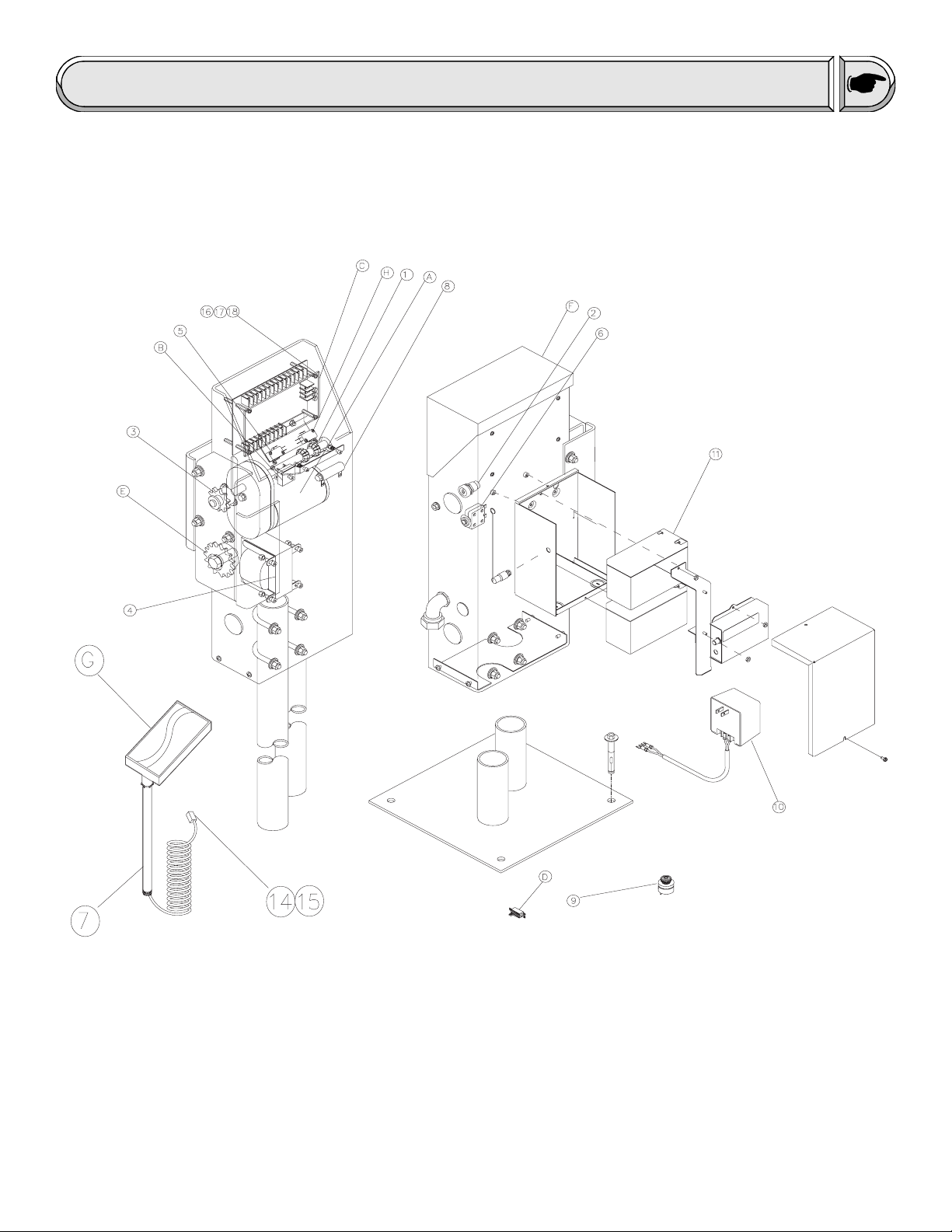
Parts Identification
7
Parts Identification continued...
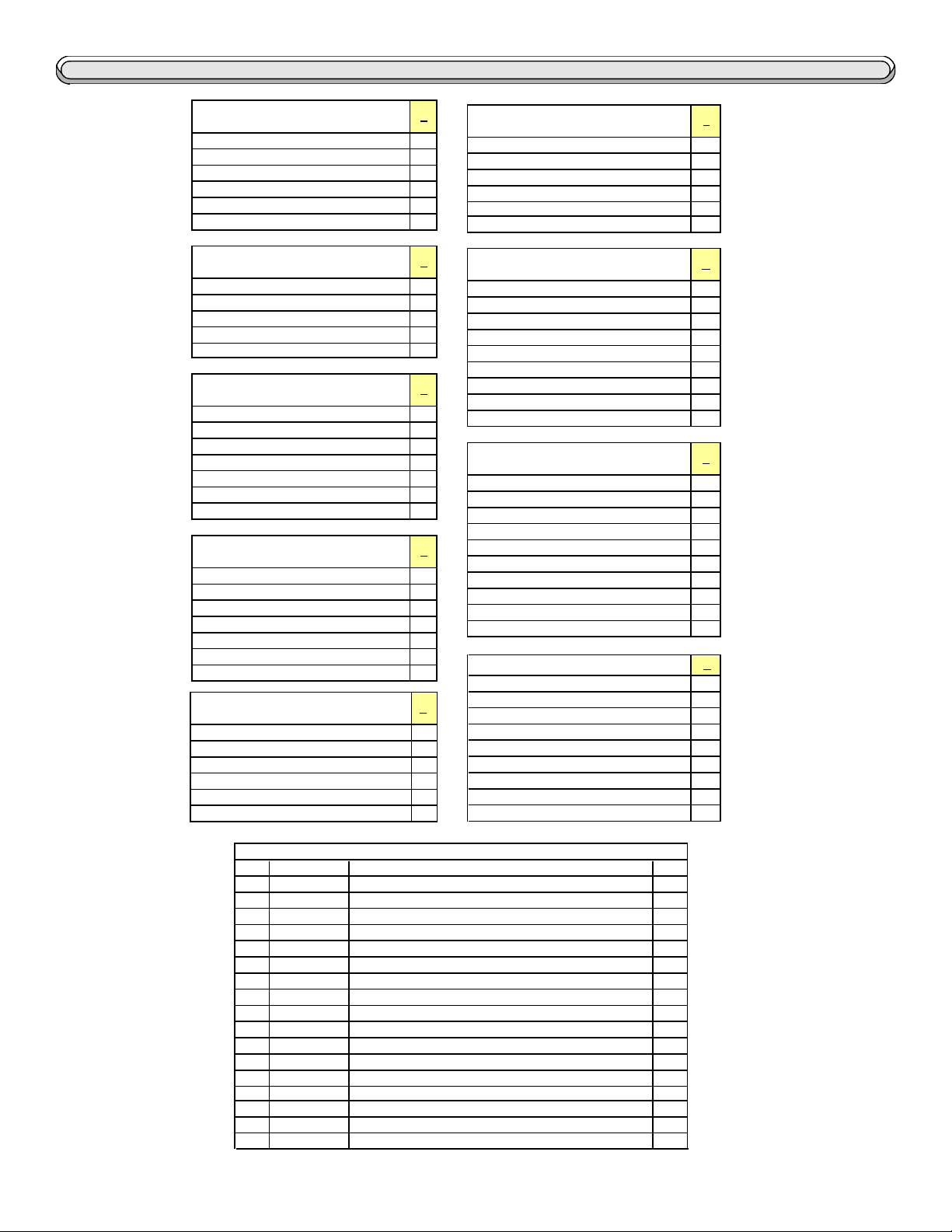
K75-40047 SERVICE KIT
MOTOR REDUCER ASSEMBLY
DESCRIPTION QTY
LIMIT NUT 2
MOTOR,REDUCER, 12 VOLT DC 1
HEX BOLT, 3/8-16 X 3/4" 3
FLATWASHER, 3/8" 3
LOCKWASHER, 3/8" 3
K74-40084 SERVICE KIT
BRIDGE RECTIFIER
DESCRIPTION QTY
CAPACITOR, RECTIFIER
BRIDGE RECTIFIER 1
SCREW, PH PHILLIPS, #6-32 X 1" 1
FLANGE NUT, 6-32 1
K74-40045 SERVICE KIT
PCB GUARD AND STANDOFF
DESCRIPTION QTY
GUARD, PCB 1
JUMPER, PCB 3
HEX STANDOFF, 6-32 x 1", M/F
HEX STANDOFF, 6-32 x 1/2", F/F
SCREW, PH PHILLIPS, #6-32 X 1/4" 4
SCREW, PH PHILLIPS, #6-32 X 3/8" 4
K74-40065 SERVICE KIT
EXTERNAL RESISTOR
DESCRIPTION QTY
EXTERNAL CURRENT RESISTOR
SHRINK WRAP, 1" 2
SCREW, PH PHILLIPS, #2-56 X 1/2" 2
LOCKNUT, #2-56 2
WIRE, GREEN, 8", STIP X FORK 1
WIRE, YELLOW, 8", STIP X FORK 1
K75-40068 SERVICE KIT
IDLER SPROCKET
DESCRIPTION QTY
SPROCKET, 41B14, 3/16" KW, (2) 1/4" SS 1
BEARING, 1/2" ID x 3/4" OD x 1/2"
HEX BOLT, 5/8-11 X 2-3/4", GRADE 5 1
HEX JAM NUT, 5/8-11 2
LOCKWASHER, 5/8 1
A
COVER, SL505 1
LABEL, BUBBLE, 4" X 2" 1
SCREW, SOCKET, 3/8-16 X 1" 1
FLATWASHER, 3/8" 1
WASHER, 5/16, INTERNAL GRIP, PLASTIC 1
B
1
C
4
4
D
1
E
1
SOLAR BRACKET
SOLAR PANEL, 12V, 5 Watt
MODULAR CONNECT, SP, WHITE
MODULAR CONNECT, SP, YELLOW
SCREW, PH PHILLIPS, #8-32 X 5/8" 2
SCREW, PH PHILLIPS, #1/4-20 X 5/8" 2
FLANGE NUT, 8-32 2
FALNGE NUT, 1/4-20 2
LIMIT SWITCH 2
RUBBER GROMMET, 7/16" DIA.x 1/16"
SCREW, PH PHILLIPS, #4-40 X 5/8" 4
SCREW, PH PHILLIPS, #8-32 X 5/8" 2
FLANGE NUT, #8-32 2
LIMIT ACTUATOR BRACKET 1
LOCKNUT, #8-32 2
SCREW, PH PHILLIPS, #8-32 X 1" 2
SPRING, LIMIT PLATE 2
K74-40041 SERVICE KIT
OPERATOR COVER
DESCRIPTION QTY
K74-40032 SERVICE KIT
SOLAR PANEL (OPTIONAL)
DESCRIPTION QTY
K74-40044 SERVICE KIT LIMIT
LIMIT SWITCH AND PLATE
DESCRIPTION QTY
K74-19915 RADIO / BATTERYSERVICE KIT
DESCRIPTION QTY
BOX
STRAP
RECEIVER
90 DEGREE ANTENNA
12 V DC BATTERY
#8 NUT
COVER
SCREW
F
G
1
1
1
1
H
1
I
1
1
1
1
2
3
1
2
INDIVIDUAL PARTS
ITEM
PART #
13-40067
1
02-40075
2
3 15-41B11CCB SPROCKET, 41B11, ½" BORE, ½ KW, 2SS 1
21-40074
4
23-40050
5
25-40083
6
28-40029
7
29-40071
8
29-40089
9
29-40095
10
11 29-NP712 BATTERY, 12V 7AH 2
81-40034
14
81-40035
15
16
K79-40056
K79-40091
17
K79-40098
18
25-2015
19
LIMIT NUT 2
KEY RELEASE SWITCH, 10A, SPST
XFMR, 120V, 60HV 1
LIMIT SWITCH 2
OVERLOAD, 1.5 AMP 1
PIPE, 1" NPT X 24"
RESISTOR, 1 OHM, 25W, OHMITE
SONALERT PIEZO ALARM
CHARGER, BATTERY 12V.5A DUAL STG 1
MODULAR CONNECT, SP, WHITE
MODULAR CONNECT, SP, YELLOW
PCB, COMPLETE, FULL SYSTEM 1
PCB, COMPLETE, SL505-BR 1
PCB, COMPLETE, SOLAR 1
OVERLOAD, 15AMP 1
DESCRIPTION QTY
8
1
2
1
1
1
1

Installation
1
2
The tail end of the gate should
extend approximately 18 inches beyond
the edge of the driveway. If this is not the
case, an extension tail will need to be
added to the gate. This will give room for
the gate operator. Make the extension
tail 18" X 18" as shown. If the gate has
not yet been fabricated, add 18" to the
length of the gate.
Remove the gate operator from
it's package and make sure that all parts
are included. Refer to General Information
and Parts Identification.
If the gate operator will be post
mounted, insert the two supplied mounting posts into the bottom of the gate
operator and through the u-bolts. The
posts should insert 5 inches into the
operator. Firmly tighten the u-bolt nuts to
securely fasten the posts.
3
Refer to figure 3 to determine the
operator location and dig a post hole
approximately 25 inches deep or more.
Set the operator with posts attached into
the post hole and fill the hole with
cement. While the concrete is setting, recheck the position of the gate operator so
that it is positioned as in figure 3 at left.
9
 Loading...