

Page 1
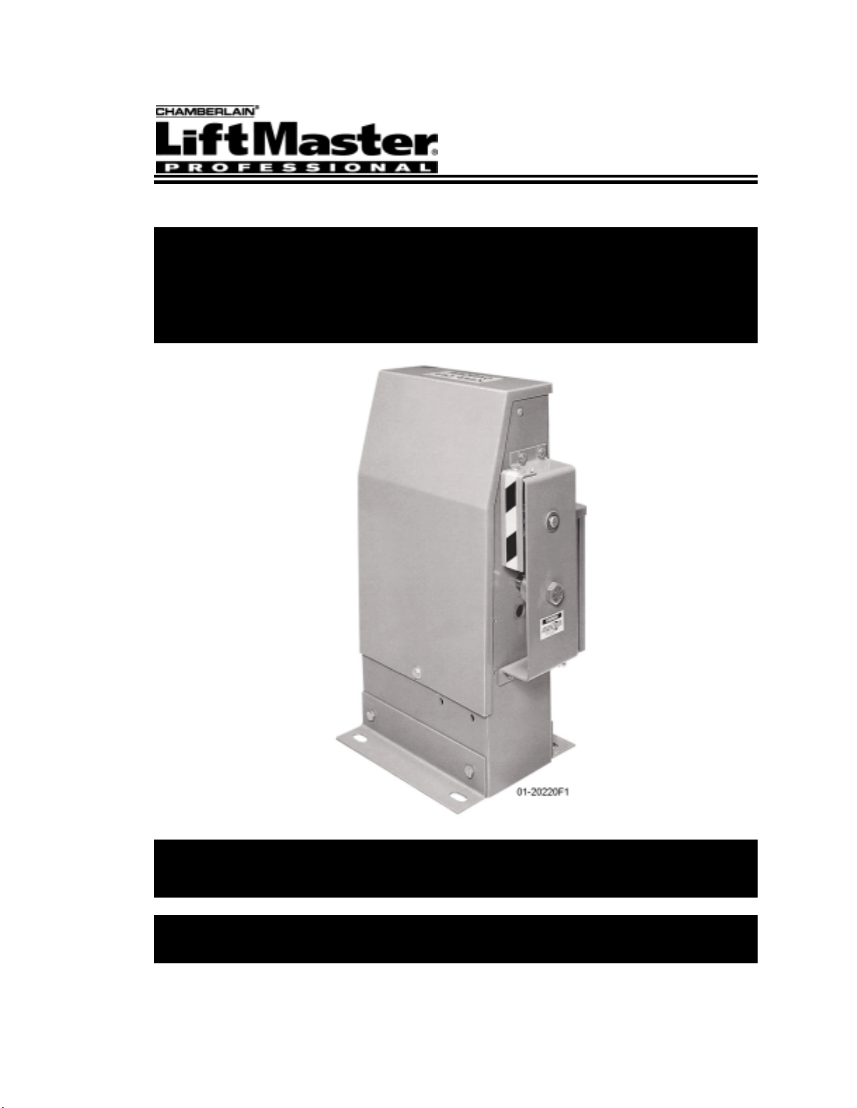
Installation and
Maintenance Manual
Slide Gate Operator
Model SL500-11
Doc 01-20220
Rev D
Page 2

Contents
2
Contents
General Information ____________________________________________ 4
Supplied Parts ___________________________________________________________ 4
Cycle Rate ______________________________________________________________ 4
Specifications ___________________________________________________________ 5
Dimensional Outline ______________________________________________________ 5
Safety Information______________________________________________ 6
Safety Instructions________________________________________________________ 6
Safety Precautions for Open-Roller Gates and Ornamental “Grill Type” Gates ________ 8
Preparing the Installation _______________________________________ 10
Pre-installation Check List ________________________________________________ 10
Wiring Specifications ____________________________________________________ 10
Operator Features _______________________________________________________ 11
Programmable Features___________________________________________________ 14
Led Descriptions ________________________________________________________ 15
Installation___________________________________________________ 16
Step 1: Mounting Legs __________________________________________________ 16
Step 2:
Step 3: Mounting ______________________________________________________ 18
Step 4: Gate Brackets ___________________________________________________ 18
Step 5: Drive Chain_____________________________________________________ 19
Step 6: Chain Guards ___________________________________________________ 19
Step 7: Battery Install___________________________________________________ 20
Step 8: Electrical Power Connections_______________________________________ 21
Step 9: Programming ___________________________________________________ 22
Step 10: Limit Switch Adjustments _________________________________________ 27
Step 11: Preliminary System Check-Out _____________________________________ 28
Pedestal Post (Optional) ___________________________________________ 17
Step 12: Accessory Installation_____________________________________________ 28
Required Maintenance__________________________________________ 30
Doc 01-20220
Rev D
Page 3

Contents
Troubleshooting _______________________________________________31
1. Power ______________________________________________________________ 31
2. Accessories__________________________________________________________ 32
3. Programs/Features ____________________________________________________ 32
4. Operator ____________________________________________________________ 33
General Reference Information_____________________________________________ 34
Warranty _____________________________________________________36
FCC Radio Usage Limitations _____________________________________________ 36
Parts List _____________________________________________________37
3
Doc 01-20220
Rev D
Page 4

4
General Information
General Information
Supplied Parts
Inspect the operator for any possible shipping damage and any shortage of parts.
Please not that if accessories were ordered with this unit, some may be packed
separately.
Part Description QTY.
Roller Chain 1
Chain Bracket 2
Chain Stud 2
Master Link 2
Chain Guard 2
Battery 1
3/8 Flat Washer 4
5/16 Lock Washer 4
5/16 – 16 Hex Nut 4
¼ - 20 Bolt 4
¼ - Lock Washer 4
Gate Caution Sign (!)2
Safety Instructions 1
Wiring Diagram 1
! Install
Gate Caution
Cycle Rate
Gate opening
in feet
NOTE:
possible, try to keep the cycles per hour at 75% of these figures.
Table 1
signs on both sides of the gate where they can be easily seen.
Frequency of Use - Cycles Per Hour
(cycle equals 1 full open and 1 full close)
Cycles per hour
22 16 13 11 9 8
12
16
20
!
!
!
Table 2
These figures are maximum and should not be exceeded. When at all
Doc 01-20220
Rev D
Page 5

Specifications
General Information 5
MODEL
SL500-11 9” per sec. 150 w. 12.4 amp 20 ft 400 lbs
GATE
SPEED
MOTOR
WATTAGE
FULL LOAD
Table 2
MOTOR
CURRENT
FULL LOAD
MAXIMUM
GATE
OPERNING
MAXIMUM
GATE
WEIGHT
Dimensional Outline
Figure 1
01-20220F1
Doc 01-20220
Rev D
Page 6

6
Safety Information
Safety Information
Vehicular gate systems provide convenience and security. Gate systems are
comprised of many component parts. The gate operator is only one component. Each
gate system is specifically designed for an individual application.
Gate operating system designers, installers and users must take into account the
possible hazards associated with each individual application. Improperly designed,
installed or maintained systems can create risks for the user as well as the bystander.
Gate systems design and installation must reduce public exposure to potential hazards.
A gate operator can create high levels of force, in its function as a component part of a
gate system. Therefore, safety features must be incorporated into every design.
Specific safety features include:
Gate Edges Enclosed Track Vertical Posts
Guards for exposed
rollers
Screen Mesh
Important instructions follow. These instructions are intended to highlight certain safety
related issues. These instructions are not intended to be comprehensive. Because
each application is unique, it is the responsibility of the purchaser, designer, installer
and end user to ensure that the total gate system is safe for its intended use.
Photo-electric
Sensors
Instructional and
Precautionary Signage
Safety Instructions
Select instructions are highlighted with this precautionary symbol (see left margin).
Failure to follow these selected instructions can result in serious injury or death.
STEP 1: BEFORE INSTALLATION
1
Confirm gate operator model is specified by Installation and Maintenance
Manual for application type, gate size and frequency or use.
2
Confirm ALL appropriate safety features, such as gate edges, photo-electric
sensors, vertical posts and enclosed tracks, are specified.
3
Confirm gate system design reduces pinch points and protects against
entrapment.
4
Confirm gate system design has pedestrian access separate from vehicular
entrance.
5
6
7
8
9
10
Doc 01-20220
Rev D
Confirm gate system design reduces traffic backup.
Confirm warning signage is included in design.
Confirm gate moves freely before installation of operator
Repair or service worn or damaged gate hardware before installation of
operator.
To avoid installation hazards, review the gate system operation and
installation procedures, such as manual disconnect mechanism procedure.
Confirm control design prohibits unauthorized use.
Page 7
STEP 2: DURING INSTALLATION
1
Disconnect power at service panel before making any electrical connection.
2
Avoid pinch points, be aware of all moving parts.
3
Adjust clutch or load sensing device to minimum force setting.
4
Do not over-tighten cutch or adjust force setting above minimum.
5
Install controls where user cannot touch gate while operating controls.
6
Install controls where user has full view of gate operation.
7
Install two or more warning signs on the gate to alert persons in the area of
automatic gate operation. Warning signs must be conspicuous.
8
Install operator inside fence line. DO NOT install operator on public side of
fence line.
9
Secure gate operator cover.
STEP 3: AFTER INSTALLATION
1
Test all safety features.
Safety Information 7
2
Train end user about basic functions and safety features of gate system.
3
Leave Installation and Maintenance Manual and Safety Instructions with
end user.
Doc 01-20220
Rev D
Page 8
8
Safety Information
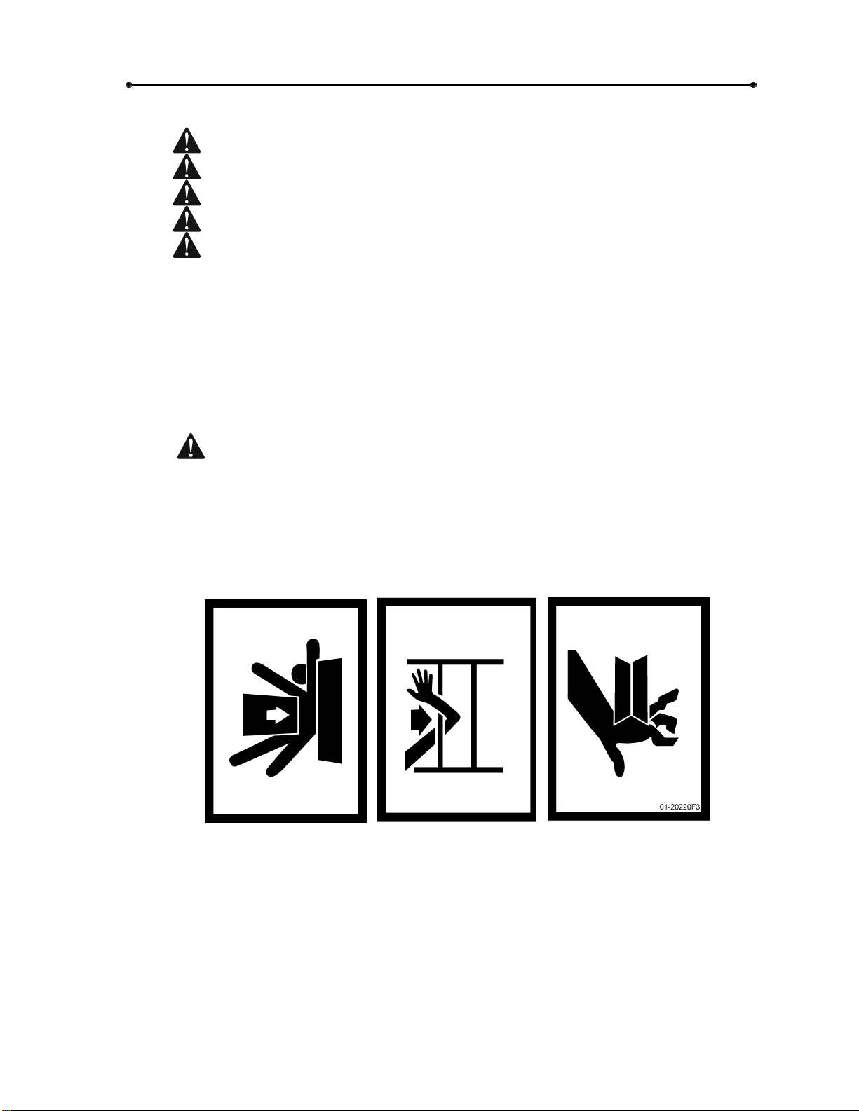
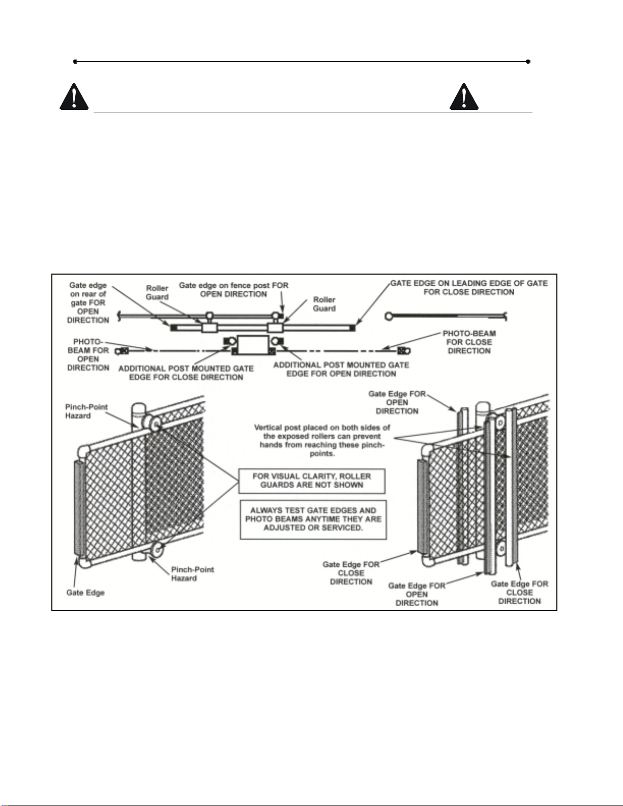
Safety Precautions for Open-Roller Gates and Ornamental “Grill Type” Gates
OPEN-ROLLER GATES
Injuries occur when people get their or feet caught between the top or bottom of the
gate and the gate roller. This potential pinch-point should be guarded against at all
times. Enclosed style gate tracks are available for refitting of these rollers from
many fence suppliers. Also, roller guards are available for installing over the
rollers.
One ore more contact sensors shall be located at the leading edge, trailing edge,
and post-mounted both inside and outside of a vehicular horizontal slide gate.
Doc 01-20220
Rev D
Figure 2
Page 9
Safety Information 9
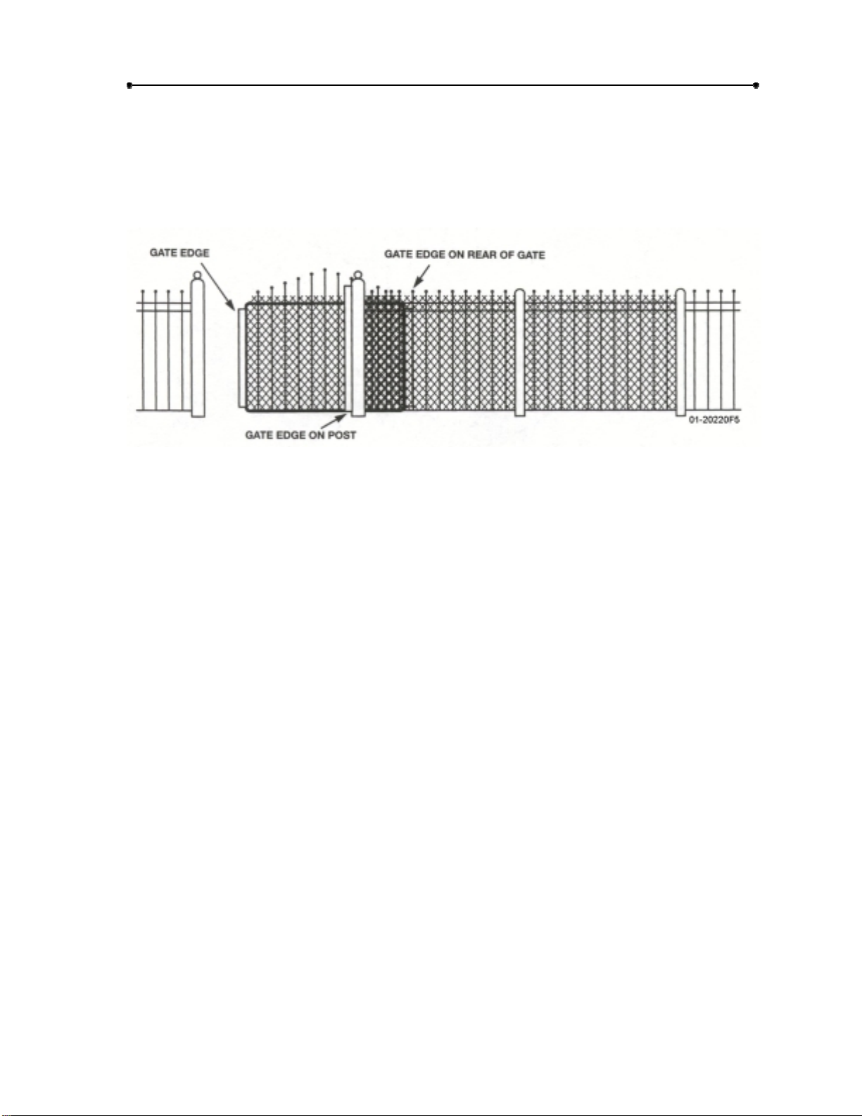
ORNAMENTAL “GRILL TYPE” GATES
Injuries occur when people put their hands and arms through openings in the grill
and the gate is operated. They cannot retract their arms and it gets caught between
the moving gate grill and the stationary fence post or fence. This potential hazard
can be averted by placing a screen mesh on the gate to prevent access through
openings anywhere the gate may travel.
Figure 3
Doc 01-20220
Rev D
Page 10
10
Preparing the Installation
Preparing the Installation
Pre-installation Check List
! Check the gate. It MUST
operate smoothly and freely. If
necessary, lubricate, adjust or
repair the gate prior to operator
installation. The gate MUST be
level and plumb.
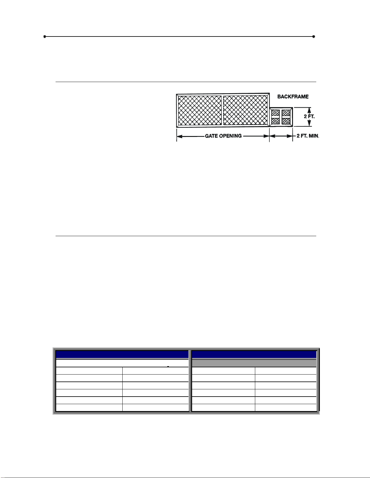
! Some gates may only be as
wide as the gate opening. They
may require a backframe to be
constructed to allow for chain
attachments. See Figure 4.
! Double check the size and weight of the gate to make sure that this operator is
proper for this application.
! If wiring has already been installed, check to make sure it meets the following
specifications and requirements.
01-20220F6
Figure 4
Wiring Specifications
A.
The distances shown are measured in feet
from the operator to the power source.
B.
These calculations are based on the
National Electrical Code and allows fro a
5% voltage drop.
C.
Supply voltage must be within 10% of the
operator’s rating under load conditions.
D.
These calculations are based on stranded
copper wire.
E.
It is highly recommended that only 90% of
the distances shown be used; this will allow
for a 10% safety factor.
F.
For dual units, the distance shown
should be cut in half.
G.
When wire larger than 12 gauge is
used , a separate junction box will
be required for operator power
connections. Not supplied .
H.
All local codes must be strictly
adhered to.
I.
Do not run control wires in the
same conduit with power wires.
J.
Do not run or parallel conductor
cable for controls.
Single Phase – 120 Vac. – 60 HZ.
One Way Distance Wire Gauge One Way Distance Wire Gauge
145ft. 14 1200 ft. 16
225 ft. 12 2000 ft. 14
360 ft. 10
602 ft. 8
Doc 01-20220
Rev D
POWER WIRING CONTROL WIRING
90 ft. 16 800 ft. 18
Table 3
Page 11

Preparing the Installation 11
g
DO NOT RUN OPERATOR UNTIL INSTRUCTED!
OPERATOR MUST BE PROGRAMMED BEFORE OPERATION.
Operator Features
Internal Obstruction Sensin
on Circuit Board
Motor
Brake
Power DisconnectEmergency Stop
Battery
01-20220F7
Figure 5
Circuit
Breaker
BATTERY BACK-UP
Should there be a power failure, the model SL500-11 will automatically switch over
to battery back up to run the gate. If battery is fully charged, it should be able to
run a standard size gate many complete cycles, (cycle = one full open and one full
close). The number may vary depending on idle time and weather conditions.
Battery specifications – Type = Sealed lead acid. Amp hours = 6.5 Max. charging
volt. = 13.7 BATTERY PRECAUTIONS:
NEVER place battery near or in fire.
NEVER short the terminals.
NEVER disassemble the battery.
If dilute sulfuric acid contacts skin or clothes, wash immediately with water
and contact a doctor.
Doc 01-20220
Rev D
Page 12

12
Preparing the Installation
.
INTERNAL OBSTRUCTION SENSING
Built-in motor current monitor. Will automatically “Learn” the current that the motor
is using to open and close the gate. During gate operation, should the current rise
above the learned setting (because of gate obstruction), the model SL500-11 will
react. See program settings for more details.
POWER DISCONNECT SWITCH/EMERGENCY STOP
This switch will turn power (120 vac.) off at the operator. Will also act as an
emergency stop. When turned off, the operator will immediately stop if it was
running.
SPRING APPLIED, ELECTRICALLY RELEASED BRAKE
The purpose of the brake is to minimize overtravel caused by gate coasting. An
added feature of the brake is to assist in preventing backdriving of the gate. The
brake is spring applied whenever the motor is not running. Anytime the motor is
running, 12 v.d.c. is sent to the brake to electrically release it.
MOTOR (12 V.D.C. / 150 WATTS)
The motor used in the model SL500-11 is a PMDC (permanent magnet direct
current) gearmotor. The nominal characteristics of the motor are – 1/8 horsepower,
19:1 gear ratio (with all steel gears), no lkoad r.p.m. = 111, full load r.p.m. = 75, no
load amps = 2.2, full load amps = 12.4, full load torque = 75 lb. in., starting torque =
90 lb. in., and it is rated for intermediate duty.
CIRCUIT BREAKER
15 amp. circuit breaker, with manual reset. Protects the secondary circuit (d.c.
side) of the operator.
NOTE:
unit is operating from the batter, and then turned back on, the unit will NOT
work. It will only work when 120 volts are re-applied.
If the power disconnect/emergency stop switch is turned off while the
MAXIMUM RUN SHUT OFF CIRCUIT
This is a self learning circuit. It will take the average amount of time between the
opening cycle and the closing cycle and add 5 seconds to it. If this time should be
reached during operation, then this circuit will shut of the operator.
REVERSAL DELALY CIRCUIT
Will not allow the operator to instantly reverse the gate, there will be a 1-1/2 second
delay prior to operator reversing direction.
AUDIBLE WARNING
Built in sounder will activate four seconds prior to and during gate movement.
Sound level is adjustable.
DIGITAL MICROPROCESSOR CONTROL BOARD
This circuit board contains all the logic, inputs and outputs for the system. It
contains all the L.E.D.’s the programming button and displays. All input and output
Doc 01-20220
Rev D
Page 13

Preparing the Installation 13
wire connections are made to it. It is protected from voltage spikes and surges by a
“State-of –the-art” voltage clamping circuitry (See Figure 6).
01-20220F8
Figure 6
MID OPEN CIRCUIT
When a control device is wired into this circuit, it will open the gate to position
slightly greater than ½ way from the full closed position or if gate is less than ½
open. If the gate should be more than ½ way open, then the control device will
open the gate to the full open position. If the time delay to close is enabled, the
operator will automatically close from the “mid-open” position.
VEHICLE REVERSE CIRCUIT
If this circuit is energized while gate is closing, gate will stop and reverse to full
open position. If energized while gate is at full open or stopped between limits, it
will not allow the gate to be closed.
VEHICLE OPEN CIRCUIT
A device connected to this circuit will only open the gate. If gate is closing, it will
cause the gate to stop and reverse to the full open position.
EXTERNAL WARNING CIRCUIT
An external signaling system can be connected to this circuit that will activate
anytime the sounder in the operator is active, (4 seconds prior to and during gate
movement).
THREE BUTTON CONTROL CIRCUIT
Sequence of operation is, open/stop/close. Stop will override all other functions. If
closing, open will cause operator to stop and reverse to full open. If opening, close
will cause operator to stop and reverse to full open. If opening, close will cause
operator to stop and reverse to full close position.
ONE BUTTON CONTROL CIRCUIT
Sequence of operation is – open, stop, close, stop. If power has been interrupted,
will always open with first activation.
Doc 01-20220
Rev D
Page 14

14
Preparing the Installation
Programmable Features
PROG.1
(R.H./L.H.): Will automatically set up motor rotation, limit switch functions and
directional logic for the operator.
PROG. 2
(MASTER/SLAVE): Will set up two (2) operators to act as one, using common
controls.
PROG. 3
(CURRENT SENSOR): This program will set the current sensor for different
sensitivities of obstruction force required to make the system react.
PROG. 4
(OBSTRUCTION SENSING CLOSE): Will determine the response the operator will
make when the gate meets an obstruction while closing.
PROG. 5
(OBSTRUCTION SENSING OPEN): Will determ ine the response the operator will
make when the gate meets an obstruction while opening.
PROG. 6
(EXTERNAL REVERSE DEVICE): Will program the system to accept either a
normally open or normally closed contact type external obstruction sensing device.
PROG. 7 & 8
(TIME DELALY TO CLOSE): These two independent programs will allow the gate
to automatically close from the full open or mid open position after a programmed
amount of time.
PROG. 9
(GATE LOCK): This program will allow the use of different types of gate locks to be
used with the system.
Doc 01-20220
Rev D
Page 15

Preparing the Installation 15
Led Descriptions
Color Name Description
Green Program “On when in program mode, “OFF” when in operational mode
Red
Red
Red
Red
Red Gate
Red Gate
Red Power
External
Reverse
Maximum
Run
Current
Sensor
Right
Hand/Left
Hand
Closing
Closing
“ON” when an external reverse device was activated, “OFF” with next
input
“ON” when maximum run circuit shut operator off, “OFF” with next input
“ON” when current sensor circuit caused an operator reaction, “OFF”
with next input
“ON” when operator is programmed R.H., “OFF” when operator is
programmed L.H., “BLINKS” when operator has not been programmed
for either
“ON” anytime sounder is activated prior to and during closing
“ON” anytime sounder is activated prior to and during opening
“ON” when operator electrical power is on. “OFF” when the operator
has no power. “BLINKS” when the control voltage of the operator drops
below 10.5 VAC. See not below.
NOTE:
PROGRAM 2 (MASTER/SLAVE)
When setting up a master/slave system, both operators MUST be programmed
independently.
IMPORTANT:
IMPORTANT:
NOTE:
Table 4
The following is for a standard master/slave system.
The following is for a standard master/slave system.
Program 1:
Program 2:
Program 3:
Program 4 through 9:
One operator will be set to #1 the other will be set to #2.
One operator will be set to #1 the other will be set to #2.
Set each operator as required.
Both operators will have the same settings..
When the battery is fully charged, the red power L.E.D. will “flicker”.
Doc 01-20220
Rev D
Page 16

16
Installation
Installation
Please note that there are two basic types of power unit mounting shown here.
Mounting, using the operators two mounting legs on a concrete pad or pedestal post
mounting (pedestal post is an optional item). The installation shown here is for right
hand units (when looking outside, unit is right side). For left hand units everything is the
same, just opposite.
If there is existing concrete at the area of power unit mounting, use dimensioning
procedure called out. It is suggested that ½” threaded anchors (not supplied), be used
to secure the unit. If needed, shim the unit to
the gate!
ensure that it is level and parallel with
Step 1:
1
2
3
4
5
Mounting Legs
Layout concrete pad as detailed. See Figure 7.
Locate electrical conduit, as required, prior to
pouring concrete.
Pour concrete, ensuring that pad is level and
above the ground line.
Locate four (4) ½” threaded anchors (not
supplied) as detailed.
Allow concrete to set for at least two days
before installing power unit.
IMPORTANT: Anchors must be
positioned accurately and secure
in concrete.
Doc 01-20220
Rev D
01-20220F9
Figure 7: Typical Mounting
Page 17

Installation 17
Step 2:
1
2
3
4
5
Pedestal Post (Optional)
Layout concrete pad as detailed. See Figure 8.
Locate electrical conduit, as required, prior to
pouring concrete.
Pour concrete, ensuring that pad is level and
above the ground line.
Locate four (4) ½” threaded anchors (not
supplied) as detailed.
Allow concrete to set at least two days
before installing pedestal post and power
unit.
Part number
49425
IMPORTANT: Anchors must be
positioned accurately and secure
in concrete.
12”
01-20220F10
Figure 8: Pedestal Post (Optional)
NOTE
Figure 7 and Figure 8 display two possible ways of mounting the unit; there are
others which you may prefer.
IMPORTANT:
It is extremely important that you
double check the distance from the mounting leg to the lowest chain point.
must
You
insure that the gate itself is low enough at the bottom to reach this chain
dimension.
Doc 01-20220
Rev D
Page 18

18
Installation
Step 3:
Mounting
STEP 3A: MOUNTING TO PAD
Carefully secure the power unit the concrete pad with the drive and idler sprockets
facing the gate. It is
very important
that the unit is level and parallel to the gate.
01-20220F11
Figure 9
STEP 3B: MOUNTING TO POST
Carefully secure the power unit to the pedestal with the drive and idler sprocket
facing the gate. It is
very important
that the unit is level and parallel to the gate.
Pedestal Post
Part #49425
Figure 10
Step 4:
Secure gate bracket to the vertical front and rear posts of the gate.
Doc 01-20220
Rev D
NOTE
If a back frame was added, then secure rear gate bracket to the back frame.
IMPORTANT:
of the drive sprocket and with the bottom of the idler sprocket. Slide the gate to the
full open and full closed positions to check alignments.
Gate Brackets
The large slotted holes in gate brackets
01-20220F12
must
be level with the top
Page 19

Installation 19
Step 5:
Before proceeding, it is suggested that the gate be positioned at the half way point.
1
2
3
4
Drive Chain
Using a master link assembly, connect one of the threaded
eye bolts to each end of the drive chain. Then attach this
eyebolt to one of the gate brackets.
Thread chain around drive and idler sprockets.
If required, cut chain to proper length, then attach the
remaining eyebolt to the chain.
Attach this eyebolt to the remaining gate bracket and take
out the chain slack, using both eyebolts evenly. The
suggested amount of chain slack is no more than 1 inch of
slack for every 10 feet of chain length.
tighten chain!
Double check alignments of chain and brackets. It is
suggested that after chain is installed and adjusted, the
gate brackets be welded to the gate.
Do not over-
See Figure 11.
Gate
Bracket
Chain Guard (2)
Chain
Drive
Idler Sprocket
Chain
Sprocket
Viewed from Outside of Gate - Looking In
Figure 11
Step 6:
Using ¼” bolts and lock washers, attach both chain guards to the sprocket shield (see
Figure 11).
Chain Guards
01-20220F13
Doc 01-20220
Rev D
Page 20

20
y
Installation
OPTIONAL POST MOUNTING
If necessary, the model SL500-11 can be post mounted. Requirements are (2) two
2” x 2” posts and mounting hardware. You will need to remove the battery bracket
and the tow mounting legs to install the posts and u-bolts. After installing, replace
batter bracket.
6 1/2”
5.68”
2.73”
01-20220F14
U-Bolts
Figure 12
Step 7:
Locate the two battery wires and connect them to the battery.
Battery Install
IMPORTANT:
The red
wire MUST go to the (+) positive terminal and black wire MUST go to the (-) negative
terminal. Install battery into unit.
Batter
01-20220F15
Figure 13
NOTE:
It is highly suggested that the battery be charged before using operator.
Due to stocking inventory, installation date and weather conditions, we cannot
guarantee that the battery will be completely charged.
Doc 01-20220
Rev D
Page 21

Installation 21
Step 8:
Electrical Power Connections
Panel Box Shown
With Cover Off
01-20220F16
GRD.
Power Conduit
Switch Has Seal
Boot Over It
Figure 14
Emergency
Stop
ON
Disconnect
OFF
Electrical
Switch
CAUTION
Make sure power is disconnected at the main power source and at the
operator’s electrical disconnect switch before proceeding!
Secure the electrical power connection inside panel box. Use electrical diagram
supplied with operator. The 120 vac., single phase, 60 hz. will have – L1 (neutral), L2
(hot) and a ground lead.
The disconnect switch can also be used as an emergency stop switch, if
needed. By turning this switch “OFF”, the gate and operator will stop if
they are opening or closing.
Doc 01-20220
Rev D
Page 22

22
Installation
Step 9:
Programming
This gate controller has (9) nine programmable options which must be set prior to gate
operation. To program the controller, press and hold the “FUNCTION” select
pushbutton for 2 seconds. When the board enters the program mode, the green
program LED will turn on and the two display panels will become active.
When the controller enters the program mode and the program LED turns on, the
“FUNCTION” display panel will display “0” (zero) and the “OPTION” display panel will
display “0” (zero). To exit the program mode, at any time, press and hold the
“FUNCTION” select pushbutton for 2 seconds. The program LED will turn off, indicating
that you a re out of the program mode. The board will reset as if first powered on.
ADJUSTMENT FOR AUDIBLE
WARNING SOUND LEVEL
AUDIBLE WARNING SOUNDER
PROGRAM
EXT. REV.
01-20220f17
MAX. RUN
OBSTRUCTION
RIGHT HAND
CLOSING
OPENING
POWER
FUNCTION & OPTION
PROGRAMMING BUTTONS
INDICATOR L.E.D.s
(Light Emitting Diode)
FUNCTION & OPTION
DISPLAY PANELS
Doc 01-20220
Rev D
Figure 15
Page 23

Installation 23
PROGRAM 1 – RIGHT HAND/LEFT HAND OPERATION
Program 1 determines whether the operator is “right handed” or “left handed”. To
determine which type your gate controller needs to be set to, observe the
installation from the operator side of the gate.
0 = NOT SELECTED – OPERATOR WILL NOT FUNCTION IN THIS MODE
1 = RIGHT HANDED – OPERATOR WILL MOVE GATE FROM LEFT TO
RIGHT TO OPEN
2 = LEFT HANDED – OPERATOR WILL MOVE GATE FROM RIGHT TO
LEFT TO OPEN
If the operator is on the right side of the opening, the operator is “right
handed”.
If the operator is on the left side of the opening, it is “left handed”.
1
Press the FUNCTION select button to set
the function to “1”.
The option display will show
a “0”, “1” or “2”.
Option “0” is the factory setting and does not
allow gate movement.
2
Pressing the ”OPTION” button will change
the option between “1” and “2”.
When the correct option for your application
is indicated, press the “FUNCTION” select
button to save this selected option and to
step to the next program.
This option must be changed
to either a “1” for right hand
or “2” for left hand.
PROGRAM 2 – MASTER/SLAVE OPERATION
Program 2 selects whether the installation is a single operator or dual operators
with common controls.
0 = SINGLE GATE OPERATOR INSTALLATION
1 = MASTER GATE OPERATOR
2 = SLAVE GATE OPERATOR
1
If the “FUNCTION” display shows “2”,
proceed on as follows.
If it does not show “2” then
press the “FUNCTION” select
button to set the display to “2”.
2
The “OPTION” display will indicate a “0”,
“1” or “2”. The “0” option is the factory
setting and is for single operator gates.
3
Press the “OPTION” select button to
change the option between “0”, “1” or “2”,
where option “1” is for master operation.
The “0” option can be changed
to “1” or “2” for dual gate
operators.
Doc 01-20220
Rev D
Page 24

24
Installation
IMPORTANT:
Once all programming is completed for the master operator, you
must then program all features for the slave operator. All nine (9) programs
should be the same except for – Program 1 (R.H./L.H.). In most cases one
unit will be right handed and the other will be left hand. Program 3 (Gate
obstruction sensitivity). In some cases the two gates will require different
settings.
NOTE – MASTER/SLAVE OPERATION:
The two operators must have the 3
interconnection wires in place between the two operators for the master/slave
system to work. Reference the wiring diagram supplied with units.
PROGRAM 3 – GATE OBSTRUCTION SENSITIVITY SELECT
Program 3 selects the force required to make the internal speed sensor react.
0 = MINIMUM FORCE SETTING
1 = MODERATE FORCE SETTNG
2 = MEDIUM FORCE SETTING
3 = MAXIMUM FORCE SETTING
1
If the “FUNCTION” display shows “3”,
proceed on as follows.
The “OPTION” display indicates a “0”, “1”, “2”
or “3”. The “0” option is the factory setting.
If it does not show “3” then
press the “FUNCTION”
select button to set the
display to “3”.
2
Press the “OPTION” select button to change
this setting to ei th e r”1”, “2” or “3”.
Option “0” is the most sensitive setting. It will
only take a small amount of force to make
the sensor react.
Option “3” is the least sensitive setting, in this
setting. It will take the most force at the gate
to make the sensor react.
IMPORTANT:
Always select the lowest option number that will function
properly with your gate application.
NOTE:
After you have completed all programming and are testing out the
system, you may have to come back to this program and make some
refinements for proper gate operation. Press the “FUNCTION” select button
to save this selected option and to step to the next program.
PROGRAM 4 – REVERSE WHEN CLOSING
Program 4 determines the response of the gate operator to an obstruction from
either the internal sensor or an external obstruction signal while closing.
0 = REVERSE FOR 2 SECONDS THEN STOP
1 = REVERSE TO FULL OPEN POSITION
With “FUNCTION” display showing “4”, press the “OPTION” select button to select
either “0” or “1”. The factory setting is “1”.
Doc 01-20220
Rev D
Page 25

Installation 25
PROGRAM 5 - REVERSE WHEN OPENING
Program 5 determines the response of the gate operator to an obstruction from
either the internal sensor or the external obstruction circuit, (#6 on wiring diagram),
while opening.
0 = REVERSE FOR 2 SECONDSTHEN STOP
1 = STOP
With “FUNCTION” display showing “5”, press the “OPTION” select button to choose
either “0” or “1”. The factory setting is “1”.
IMPORTANT:
Programs 4 and 5 are only for the internal sensor and for the
external obstruction device (adaption #6 on wiring diagram). Note that
adaption #5, shown on wiring diagram (vehicle reverse device), will always
stop and reverse a closing gate to the full open position. Adaption # 7 will only
react in the closing direction.
PROGRAM 6 – EXTERNAL REVERSE DEVICE SELECT
This program determines which polarity of signal on the external obstruction device
will cause the gate operator to react.
0 = EXTERNAL REVERSE DEVICE WITH NORMALLY CLOSED CONTACTS
1 = EXTERNAL REVERSE DEVICE WITH NORMALLY OPEN CONTACTS
If a device with normally open contacts is used, then this option should be set to
“1”. If a device with normally closed contacts then this option should be set to “0”.
The factory setting is “1”.
When the correct option is displayed, press the “FUNCTION” select button to save
the choice and to step to the next program.
PROGRAM 7 – TIME DELAY TO CLOSE ENABLE/DISABLE
This program enables or disables the automatic time delay to close option.
0 = TIME DELAY TO CLOSE “OFF”
1 = TIME DELAY TO CLOSE “ON”
When the correct option is displayed, press the “FUNCTION” select button to save
the choice and to step to the next program.
NOTE:
If the timer to close option is set to disable, you will not need to do
program 8. By pressing the “FUNCTION” select button twice you will go to
program 9.
Doc 01-20220
Rev D
Page 26

26
Installation
PROGRAM 8 – TIME DELAY TO CLOSE “TIME”
This program sets the time from when the gate is fully open to the time when it will
automatically begin to close.
0 = 2 seconds
1 = 15 seconds
2 = 30 seconds
3 = 60 seconds (1min.)
4 = 90 seconds (1- ½ min.)
5 = 120 seconds (2 min.)
6 = 180 seconds (3 min.)
7 = 240 seconds (4 min.)
1
By pressing the “OPTION” select button, choose the time that
will be required for this gate application.
2
Once the selection has been made, press the “FUNCTION”
select button to save this selection and to step to the next
program.
PROGRAM 9 – GATE LOCK TYPE SELECT
If gate lock is to be used with the operator, this program determines the state of the
built-in lock relay contacts and how they will turn on and off.
0 = LOCK OUTPUT NORMALLY “OFF”
1 = LOCK OUTPUT NORMALLY “ON”
By pressing the “OPTION select button, choose either option “0” or “1”.
Option “0” would normally be selected if you are using a solenoid activated type
lock system. The built-in lock relay’s contacts will be open when gate is closed.
They will close for one second before the gate begins to open, and open up two
seconds after the gate has begun moving.
Option “1” would normally be selected if you are using a magnetic type lock system.
The built-in lock relay’s contacts will be closed while the gate is closed. They will
open up one second before the gate begins to open and remain open.
With either selection the contacts will be closed when the gate begins to close.
NOTE:
For wiring information see electrical diagram supplied with operator. If no lock
system is to be used, it does not matter which option is shown in the display.
This was the last programming option. To exit program mode, press and hold the
“FUNCTION” select button for 2 seconds. The green program LED will turn off.
Doc 01-20220
Rev D
Page 27

Installation 27
Step 10:
Limit Switch Adjustments
IMPORTANT:
1
Remove operator top cover and locate limit
switch assembly.
2
Attach activation device such as a three button
station to control terminal strip.
3
With power on and gate a the mid way point,
activate operator to open.
After unit shuts off, press detent down and adjust
open limit nut until full open position is obtained.
Operator must be programmed before operation!
Reference wiring diagram or
control wiring section further
on in this manual.
Note direction of limit nuts.
Repeat this procedure for the
full close direction.
Figure 16
01-20220F18
Doc 01-20220
Rev D
Page 28

28
Installation
Step 11:
Before adding any options, accessories or adaptions, it is highly recommended that
you check out the system and its programs. If you have not already done so, .…
! Temporarily connect a 3 button station to the control terminal strip, see next
! Test for proper open, stop and closing of gate.
! Test the internal sensor system.
! Test for proper operation of all programs that were programmed into the
! Once everything checks out okay, then proceed to adding on the accessory
Step 12:
See Figure 17 for more information.
Refer to
Preliminary System Check-Out
page or wiring diagram supplied with operator.
system.
items for this job site.
NOTE:
one is attached check it for proper operation before adding the next.
We recommend that, if more than one accessory item is used, after each
Accessory Installation
Wiring Specifications
on p. 10 for wiring distance and wire gauge information.
WARNING
Make sure that the two (2) gate caution signs are secured to the gate: one on the
inside and one on the outside. They must be easily visible. If exterior controls such
as keyswitch, card reader or pushbutton station are to be incorporated into this
system, make sure the controls are installed where the user cannot touch the gate
while operating controls. Install the controls where the user has full view of gate
operation.
Doc 01-20220
Rev D
Page 29

Installation 29
Figure 17
Doc 01-20220
Rev D
Page 30

30
p
Required Maintenance
Required Maintenance
Normal Usage
Check at least once every
MONTH INTERVALS
Internal sensor Check for proper operation
External safety systems Check for proper operation
Com
Gate caution signs Make sure they are present
Brake system Check for proper operation
lete Check Out
Drive chain (D) (E) Check for excessive slack & lubricate
Drive sprockets Check for set screw tightness
Battery back-up Disconnect power and test battery
Gate Inspect for wear or damage
Accessories Check all for proper operation
Electrical Inspect all wire connections
Frame bolts Check for tightness
Total unit Inspect for wear or damage
13612
!
!
!
!
!
!
!
!
!
!
!
Table 5
NOTES
A.
CAUTION -
When servicing, always disconnect operator from electrical power
supply.
B. Severe or high cycle usage will require more frequent maintenance checks.
C. Inspection and service should always be performed anytime a malfunction is
observed or suspected.
D. Limit switches may have to be reset after any major drive chain adjustments.
E. If lubricating chain, use only a proper chain lube spray or a lightweight motor
oil. Never use grease or silicone spray.
F. When servicing, please do some “house cleaning” of the operator and the area
around the operator. Pick up any debris in the area. Clean the operator if
needed.
G. It is suggested that while you are at the site, you take some voltage readings of
the operator. Using a VOM, double check the incoming voltage to the operator
is
to make sure it
within ten percent of the operator’s rating.
H. While you are at the site, now would be a good time to let the owner or
manager know about any new items available or any safety items that could
and should be added to the site.
IMPORTANT:
I.
Please leave this manual at the job site, preferably with the end
user or facility manager.
Doc 01-20220
Rev D
Page 31

Troubleshooting
Troubleshooting
When troubleshooting, one of the first things to do is try to isolate the problem area. The
four (4) main areas to check out are:
POWER
ACCESSORIES
PROGRAMMING
OPERATOR
1. Power
Always use extreme caution! Some possible symptoms of power problems include:
! The obvious one – the operator will not run.
! The operator runs slow.
! Circuit breakers or fuses keep tripping.
31
! Operator starts but then stops.
1A.
Using a V.O.M. take a voltage reading at the control transformer’s primary
terminals. You should get a reading as follows:
Nominal volt. Min. Max.
120v 108 132
If you get a reading that does not fall into the minimum/maximum area, then check
out your main power supply. Check the wire run from the power supply to the
operator. Double check the gauge of the wire versus the distance.
1B.
If the voltage reading is O.K. from 1 a, then take the same voltage reading with the
operator running. If voltage drops below the minimum with this reading, then there
could be an excessive current draw somewhere.
1C.
In some cases, power drops can occur at only specific times during the day or
night. This can be caused by increased power demands in a general area at a
specific time.
Doc 01-20220
Rev D
Page 32

32
Troubleshooting
2. Accessories
Add-on accessories can create many of the problems that are credited to the operator.
Many applications have more than one accessory item attached to the operator and
some of these items even draw their power from the operator. So, before we start
blaming the operator, let’s take a look at all the add-on’s first.
Some of the symptoms that can show up because of accessories include:
! The operator won’t close.
! The operator won’t open.
! The operator will not run.
! The operator begins to run then stops or reverses.
2A.
Whenever the problem is thought to be an accessory and there are more than one
connected to the operator, always disconnect one accessory at a time and then test
the system. This will hopefully isolate which item is causing the problem.
2B.
If an accessory
close), fails in the closed position or sends out a continuous signal. The operator
will hold the gate in one position until the signal from the accessory is removed.
item
is being used as an access control device (used to open or
2C.
In some applications, the gate may begin to move then either stop or stop and
reverse within a couple of seconds. This can be caused by an external obstruction
device that has failed.
3. Programs/Features
In many cases, unawareness of the programs and their functions can make it look like
in
there is a problem when
Before you start tearing things apart, please review pages 8, 12, 13 & 14.
Always use the LE.D.’s that are on the circuit board. They will normally lead you to the
particular area to check out.
3A.
PROGRAM 1 - R.HJLH.: If not programmed for either one, the operator will not
work. Check LE.D.
3B.
PROGRAM 2- MASTER/SLAVE: If you have a single unit and have the program
set for master, the operator will not work. It MUST be set to #0. When programming
for master/slave, both operators MUST be programmed individually.
actuality it is just missed or wrong program mode setting.
Doc 01-20220
Rev D
Page 33

Troubleshooting 33
3C.
PROGRAM 3- CURRENT SENSOR: A damaged or poorly working gate can trip
the sensor and cause what is called, “phantom reversal or stopping”. Also,
excessive wind loads can cause the sensor to react. Double check the sensor
settings.
3D.
PROGRAMS 4 & 5- OBSTRUCTION REACTION SETTINGS: Please review these
programs.
3E.
PROGRAMS 6- EXTERNAL REVERSE DEVICE: If this program is set the opposite
from what the device is, the gate will not move.
3F.
PROGRAMS 7, 8 & 9: Please review these programs.
3G.
When in the program mode (green LE.D. on), the operator will not work.
3H.
The operator will automatically exit the program mode if no button (function or
option) is pressed within five minutes.
3I.
MAXIMUM RUN SHUT OF CIRCUIT: This is a built in self learning circuit. It will
automatically shut off the operator after the amount of time to open plus 5 seconds.
LED will indicate activation.
3J.
Mid open circuit. If terminals #4 and #6 are activated, operator will only open to
approximately the 1/2 way position.
4. Operator
4A.
The transformer is: 120 vac,. input /1 2vac. output / 100 Va. If the transformer is
suspected, check for proper voltages.
4B.
If the motor sounds like it’s running but the gate is not moving, there is a possibility
that there is a broken gear tooth inside the gear box. To test for this, carefully while
try
the motor is running,
broken tooth or two.
pushing the gate. If it starts to move then there might be a
Doc 01-20220
Rev D
Page 34

34
Troubleshooting
4C.
To check the brake. First take a V.O.M. reading at the terminals where the two
brake leads are connected at the circuit board. You should get 12 vdc. there when
the motor is running. If not, then the circuit board should be replaced. Second, with
try
gate either opened or closed,
to move. If it is very easy to move then the brake has mostly likely failed and the
entire gear motor should be replaced.
manually moving the gate. It should be
very
hard
4D.
If unit will not run, double check the circuit breaker on side of operator. Push button
on circuit breaker.
4E.
wires.
run
from the battery. First check the battery for voltage and current.
see
12 vdc. at
If unit does not
Second, remove the two wires from the battery and using V.O.M. take a voltage
reading from the two wires. When 120 vac. is active you should
these
two
4F.
The two limit switches used are S.RD.T. (single pole double throw). Each has two
wires attached to it, one on the common and one on the normally open side (N.O.).
The limit switch designations are LS-1 and LS-2. LS-1 is the open switch when the
and
operator is programmed for “right hand”
switches are opposite when the unit is programmed for “left hand”.
LS-2 is the closed switch. The two
4G.
If a three button station or a normally closed (N.C.) stop button is not used, there
MUST be a jumper placed between terminals #2 and #4 (stop & common). If a
three button station or stop button is used, then this jumper MUST be removed. If
wire is not there when it should be, the operator will not work. If it is there when it
should not be, the operator will not stop when the stop button is pressed.
4H.
ALWAYS double check the wire connections at the terminal strips. Make sure that
the wire itself, not the insulation of the wire is being clamped down on. Also check
for a loose wire connection.
General Reference Information
THE GATE
Double check the gate and its related hardware. Does the gate move freely? If it
does not, this can and will affect the unit’s internal obstruction sensor.
WIRING DIAGRAM
Always reference the wiring diagram for this operator. Note that some accessory
items may have their own wiring diagram.
Doc 01-20220
Rev D
Page 35

Troubleshooting 35
COMPONENT DESCRIPTIONS
A. GEAR MOTOR WITH BRAKE -12 v.d.c. permanent magnet, rated horsepower
1/8, no load r.p.m.
=
12.4, gearbox ratio = 19 to 1, duty cycle = intermittent, brake is spring activated
12 v.d.c. to release.
B. POWER DISCONNECT SWITCH - Rocker style, triple pole single throw
(T.P.S.T.), cont ac t ratings
C. TRANSFORMER - Primary voltage
100 v.a., class B insulation, built in thermal overload.
D. LIMIT SWITCH - Single pole double throw (S.RD.T.), 15 amp. @250 vac.
E. CI RCUIT BREAKER - 15 amp. © 125 v.a.c./50 v.d.c. with manual reset.
F. BRIDGE RECTIFIER - Full wave, 12 v.a.c. to 12 v.d.c., reverse voltage
volt. mm., rectified current
=
111, no load amps = 2.2, full load r.p.m. = 75, full load amps
=
15 amp. © 125 v.a.c./10 amp. ©
=
120 v.a.c., secondary voltage~ = 12 v.a.c.,
=
50
=
25 amp. m m .
G. BATTERY -
13.7, battery storage info = 6 months c~ 68 degrees F = 80% voltage, 12 months
© 68 c~rees F
hours, or 1/2 amp. for 13 hours, etc.
NOTE
No attempt at service or repair should be made on the battery!
Type = sealed lead acid, amp. hour = 6.5, maximum charging volts
=
63% voltage. Amp hours = Battery will supply 1 amp, for 6 1/2
=
Doc 01-20220
Rev D
Page 36

36
Warranty
Warranty
LIMITED ONE-YEAR WARRANTY
LiftMaster gate operators are warranted against deficiencies in material and workmanship for a period of one
(1) year from date of purchase, providing recommended installation, and maintenance procedures are
followed. This warranty is in lieu of all other warranties expressed or implied (some states do not allow
limitations on how long an Implied warranty lasts, so this limitation may not apply to you) and shall be
considered void if damage was due to improper installation or use, connection to improper power source, or if
damage was caused by fire, flood or lightning. The manufacturer will not be responsible for any labor charges
Incurred in the removal or replacement of deficient parts.
In case of failure due to deficiencies in material or workmanship during the warranty period, the complete
gate operator will be repaired or replaced at the manufacturers option. New or factory rebuilt replacements
will be used. Replacement parts are warranted for the remaining portion of the original warrant period.
LiftMaster will pay freight on our return of repaired or replaced items in warranty.
This warranty give you specific rights, and you may also have other rights which vary from state to state.
FCC Radio Usage Limitations
CAUTION:
Federal Communications Standards for part 15 radio devices. Operation of this device
is subject to the following conditions: (1) This device may not cause harmful
interference; (2) This device must accept any interference that my be received,
including interference that may cause undesired operation; (3) Changes or
modifications not expressly approved by LiftMaster could void the authority of users to
operate this equipment.
The gate operator and all accessory equipment has been designed to
Doc 01-20220
Rev D
Page 37

Parts List
1/4 - 20 X 1/2
HEX BOLT W/
LOCK WASHER
Parts List
10-32 X 1/4 SELFTAP SCREWS
W/LOCK WASHER
37
01-20220F20
10-32 X 3/8 MACH.
SCREW W/WASHER
10-24 X ¾ MACH.
SCREW W/LOCK
WASHER & NUT
REF. NO. PART NO. DESCRIPTION/NOTES
1 49429 COMPLETE PANEL BOX
2 & 3 49430 KIT, 3-R BOX & COVER
4 310.2047 TRANSFORMER ONLY
5 310.2045 RECTIFIER ONLY
6 310.1990 DISCONNECT SWITCH ONLY
7 310.2048 SWITCH COVER ONLY
8 49433
9 --- GROMMET
10 410.1457 THRU-BUSHING ONLY
STAND-OFF KIT (OPTION), FOR
OPTIONAL RADIO RECEIVER
Table 6
Figure 18
Doc 01-20220
Rev D
Page 38

38
Parts List
10-24 SCREW,
WASHER & NUT
6-32
SCREW
1/4-20 BOLT
WASHER & NUT
1/4-20 BOLT
WASHER & NUT
5/16-18 BOLT
& WASH.
10-32 SCREW
& WASHER
01-20220F21
1/4-20 BOLT
WASHER & NUT
5/16-18 BOLT,
NUT, WASHER
8-32 SCREW
& WASHER
Doc 01-20220
Rev D
Figure 19
Page 39

01-20220F22
Parts List 39
Figure 20
Ref. No. Part No. Descriptions/Notes Ref. No. Part No. Description/Notes
1
2
3
4 510.1024 Motor/Gearbox 20 645.0002 Woodruff Key
5
6
7
8 49426
9
10 23-10041 Limit Sw 26 520.0874-T
11 49427
12 49428 Stand-Off Kit - Incl: (5) 28
13 204001 Cir c uit Bd. 29
14 310.2042
15 310.2043
16 310.2044
510.1021-T
510.1022
510.1023
310.1113
520.0868 Bearing Plate Assy.
510.1027 Detent Plate
510.1029
Housing 17 310.2045 Rectifier
Mounting Angle 18 310.2046 Circuit Breaker
Battery Bracket 19 49431
Limit Nut 21 520.0870
Spring Kit - Ncl: Scr’s,
Washers, Nuts
Limit Switch Bracket 25
Limit Sw. Scr. Kit - Incl:
(2) Scr’s.
Circuit Bd. Connector -3
Pole
Circuit Bd. Connector -4
Pole
Circuit Bd. Connector -6
Pole
Drive Sprkt
Sprocket Shield Assy -
Incl: Shield & Bearing
22 625.0058 Idler Bolt
23 510,1032
24 520.0871
510.1036-T
27 49056
410.1322
310.0241 Chai n Stud Not Sh o wn
30
31 410.1457 Bushing (For Limit Brkt)
49425 Pedestal Not Shown
Support Tube
Idler Sprocket Assy -
Incl: Sprk~ & Bearing
Cover Kit. Incl: Co ver
W/Labels
Chain Guard Assy - Incl:
Guard W/Caution Tape
Battery
Chain Bracket Not
Shown
Table 7
Doc 01-20220
Rev D
Page 40

COPYRIGHT 2001
ALL RIGHTS RESERVED
This document is protected by copyright and may not be copied or adapted without the prior written
consent of LiftMaster. This documentation contains information proprietary to LiftMaster and such
information may not be distributed without the prior written consent of LiftMaster. The software and
firmware included in the LiftMaster product as they relate to this documentation are also protected by
copyright and contain information proprietary to LiftMaster.
FOR TECHNICAL SUPPORT
Call our toll free numbers:
(800) 323-2276
(800) 998-9197
Installation and service information is
available six days a week.
TO ORDER REPAIR PARTS
Call our toll free numbers:
(800) 528-2806
(800) 998-9197
Prepare to provide the following
information when ordering repair parts:
Part Number
"
Part Name
"
Model Number
"
 Loading...