

Page 1
®
™
Instruction Manual
™
SL3000UL
HIGH TRAFFIC COMMERCIAL GATE OPERATOR
UL325
compliant
installation instructions and manual book
for architects, general contractors and dealers
© 2005 the chamberlain group, inc. – all rights reserved
UL991
compliant
SERIES
LISTED
Page 2
SL3000UL
9
0
9
8
5
8
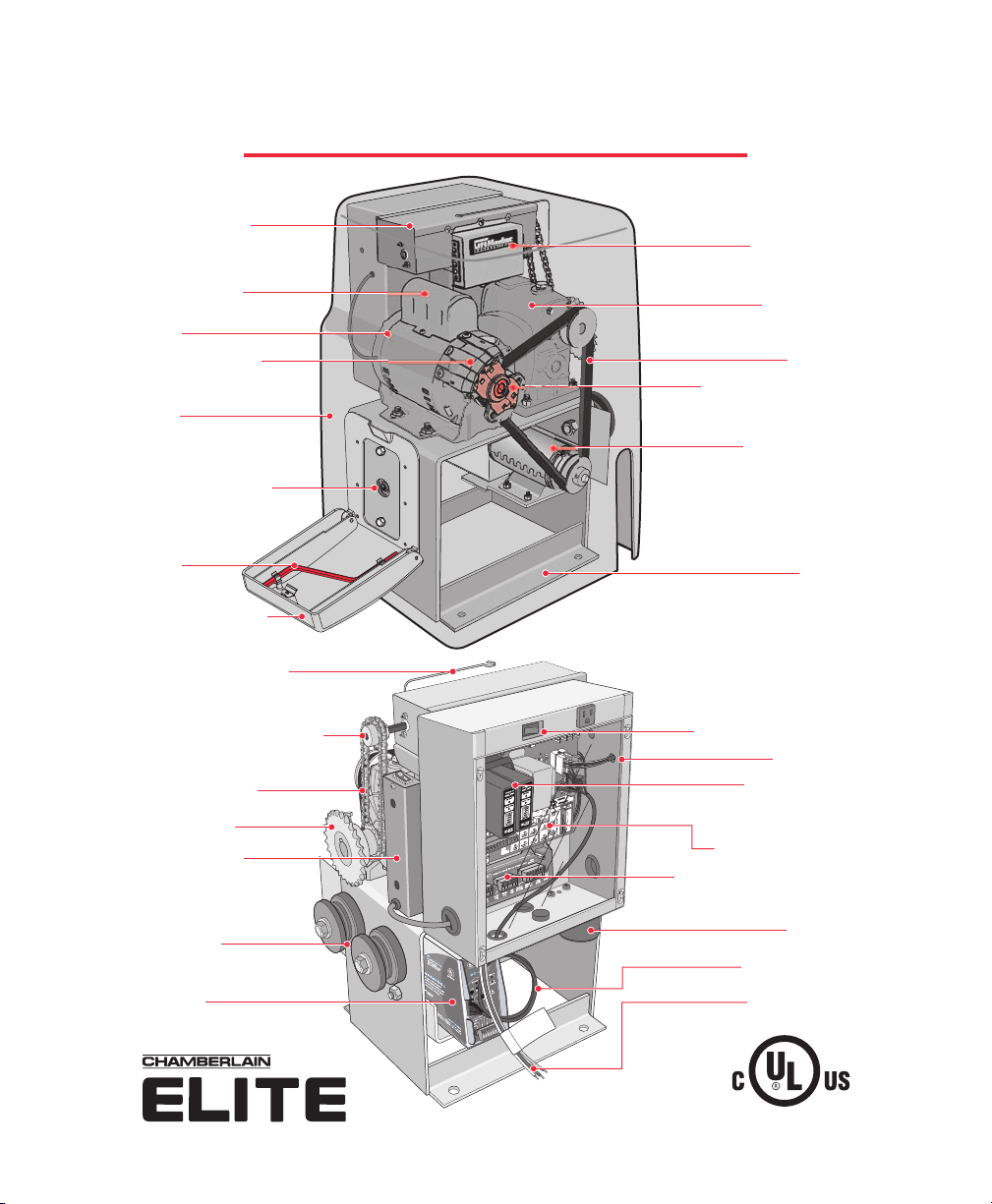
Overview
Limit Switch Box
Pg.20
Motor Capacitor
Motor
Interlock Assembly
Cover
Built-In Reset Button
Pg.24
EMERGENCY RELEASE
Crank Tool
Pg.28
Crank Tool Housing
Pg.28
™
Radio Receiver
Pg.27
Gear Reducer
Drive Belt
EMERGENCY RELEASE
Optional Factory
Installed DC2000 Battery
Models DC and DCH Only
Pg.2
Back-Up Motor
Chassis
Radio Receiver Antenna
Limit Switch Chain Sprocket
Limit Switch Chain
Drive Sprocket
Optional Factory
Installed Heater
Models H and DCH Only
Pg.33
Idler Wheels
Optional Factory Installed
DC2000 Battery Back-Up
Controller
Models DC and DCH Only
Pg.30
®
™
N
O
OFF
Operator ON OFF Switch
Control Box
Optional Plug-In
Loop Detectors
4
W
Pg.3
OmniControl™ Board
Surge Suppressor Terminal
Pg.1
UL Alarm
Pg.2
DC2000 Harness
Pg.3
N
al
0 VAC
UTIO
d
n
eutr
u
N
ck 12
CA
o
a
r
e
Bl
G
hit
W
een
r
G
SL Power Wires
Pg.1
LISTED
1
Page 3
TABLE OF CONTENTS
Safety Instructions
Role of Specifiers and Designers
Role of Dealers, Installers and Trained Gate System Technicians
Role of End Users / Home Owners
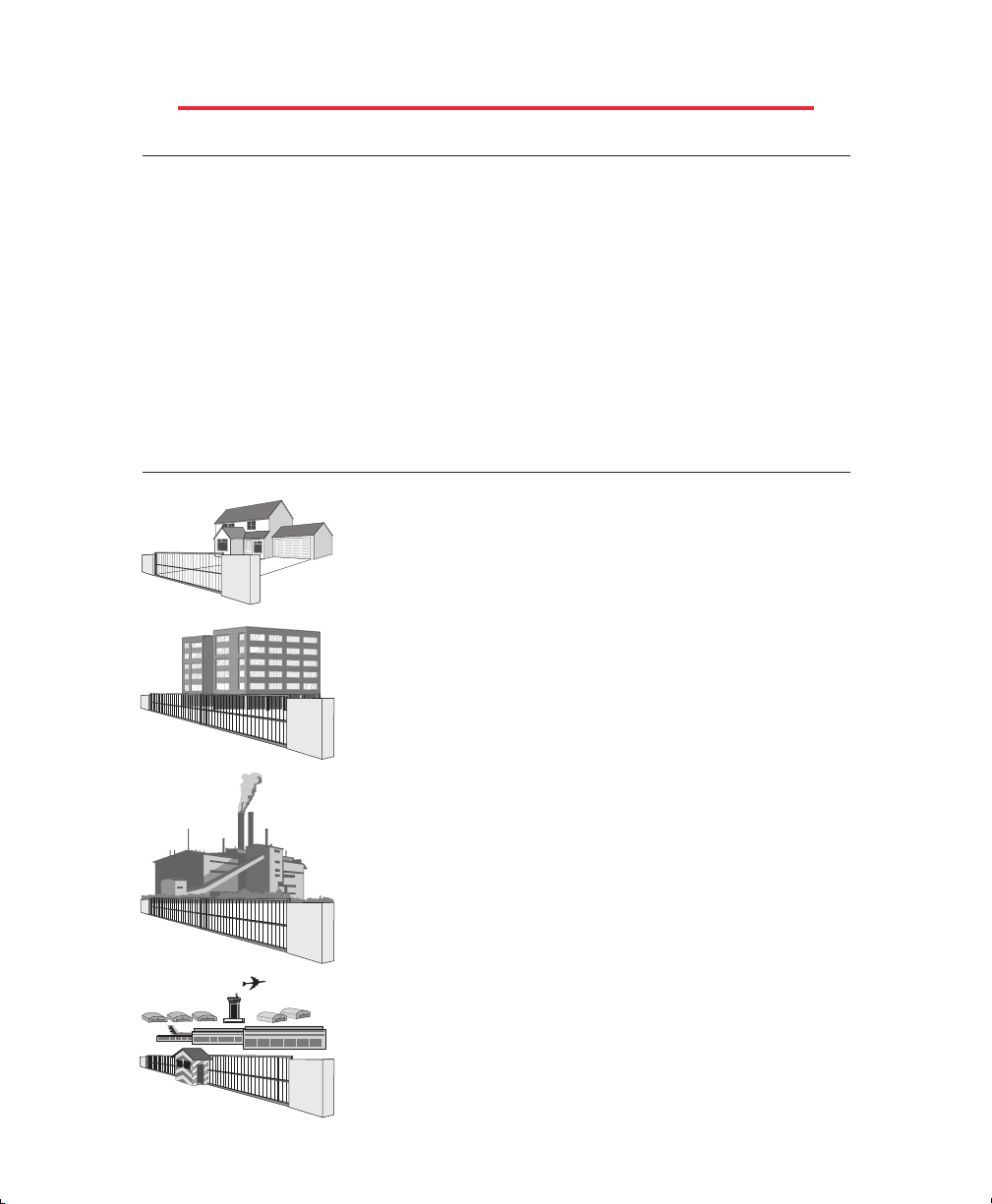
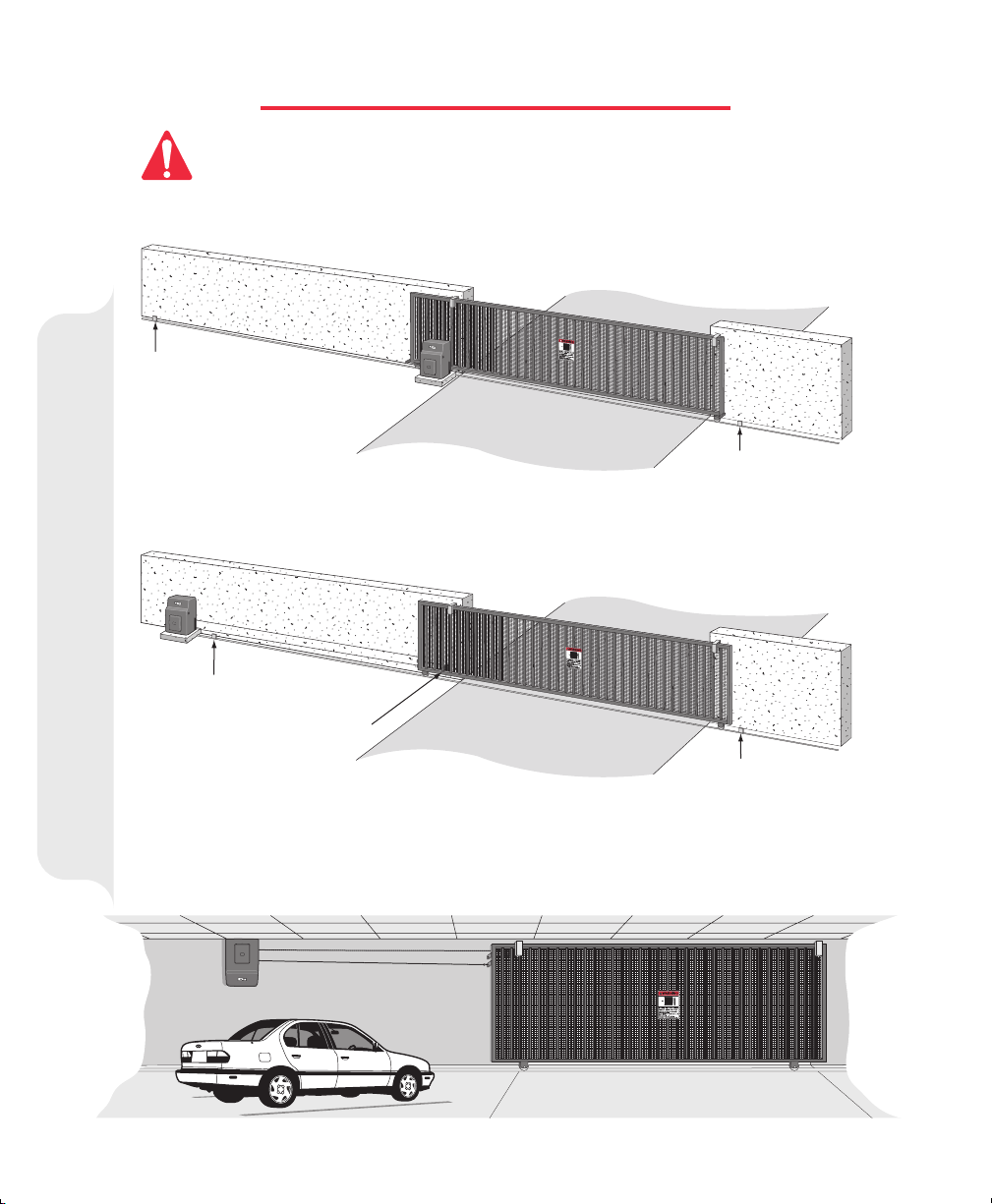
Horizontal Slide Gate Systems
UL Listings
Warnings and Precautions
Installation
Recommended Setup and Operator Specifications
Gate Post Warning
Mounting Required Warning Signs
Types of Installation
Connecting the Chain
Concrete Pad and Gate Attachment
Gate and Operator Mounting Distance
Optional
How to Connect Power (110 V)
Surge Suppressor Terminal Input Connections (Wiring Optional Equipment)
Choosing Gate Movement Direction (Open Left or Right)
Adjusting Gate Traveling Distance (Limit Switches)
Two-Way Adjustable Reversing Sensor
Adjustable Timer
Master / Second Operators with Timer On
Master / Second Operators with Timer Off
Built-In Reset Button
Table Of Contents
Remove Control Board
Audio Alarm
Solenoid/Maglock J3 Plug Connection
Radio Receiver Programming
Post Mounting Plate
4
4
5
5
6-9
10
11
12
13
14
15
15
16
17
18
19
20
20
21
21
22
23
24
25
25
26
27
EMERGENCY RELEASE
Optional
Emergency Release
28
29
Please DO NOT Touch me!..
Unless you are an Authorized
Service Technician!
© 2005 The Chamberlain Group, Inc.
All Rights Reserved.
For Technical Support: 1-800-528-2806
2
Page 4

TABLE OF CONTENTS
Optional
Optional
Wiring
Wiring
Optional
Optional
Optional
Optional
Optional
Optional
Optional
Optional
Optional
Optional
Factory Installed DC2000 Back-Up Connection. Models DC and DCH Only
Optional
Optional
Devices to DC2000
Safety Devices to DC2000
Factory Installed Heater. Models H and DCH Only
Omni Option Board Description
QCC (Quick Close Circuit)
House Alarm/Proximity Switch Connection
Master/Second Connection
Solenoid Connection
Maglock Connection
3 Push Button Station Connection
Stop Button Alarm Shut-Off Connection
Solenoid/Maglock Connection 38
Optional
Optional
Optional
Single Operator Loop Sizes and Placement
Master/Second Loop Sizes and Placement
Loop Installation and Number of Wire Turns
Plug-In Loop Detectors
External Loop Detectors
Factory Installed Equipment
Optional
Optional
Omni Option Board
Relay Adapter
Loop Detectors and Loop Setup
30
31
32
33
34
34
35
35
36
36
37
37
39
40
41
42
43
Table Of Contents
Optional
Optional
Optional
Optional
Optional
Secondary Entrapment Protection Connection (Non-Contact Sensor)
Safety Photo Electric Sensors Connection (Non-Contact Sensor)
Secondary Entrapment Protection Connection (Contact Sensor)
Safety Edge Sensor Connection (Contact Sensor)
Safety Equipment
44
45
46
47
Troubleshooting
Troubleshooting LED Information
Troubleshooting Table
48
49
Repair Parts
Parts Illustrations
Parts List
50
51
Maintenance
Maintenance 51
Property Owners Checklist of Installation 52
3
Page 5

ROLE OF SPECIFIERS AND DESIGNERS
Specifiers and designers should design an automatic vehicular gate system to:
Incorporate UL 325 compliant equipment.
•
Utilize an operator suited for gate system type, size, frequenc y of use, location and user
•
population. (Refer to UL 325 for usage class definitions)
Separate pedestrian access from vehicle access.
•
Reduce or eliminate pinch points.
•
Reduce risk of entrapment injuries by minimizing all gaps in the gate and enclosing the area of the
•
travel of the gate.
Secure controls from unauthorized use.
•
Locate all controls out of reach from the gate.
•
Allow the user full view of the gate when operating.
•
Consider special populations, such as children or the elderly.
•
Conspicuously display all warnings and instructions.
•
Be consistent with DASMA’s Automatic Gate Opener System Safety Guide.
•
ROLE OF DEALERS, INSTALLERS AND
TRAINED GATE SYSTEM TECHNICIANS
Installers, during the course of the installation proceedings for each job, should:
Confirm that the gate operator being installed is appropriate for the application.
•
Confirm that the gate is designed and built according to current published industry standards.
•
Confirm that all appropriate features and accessory devices are being incorporated, including both
•
primary and secondary entrapment protection devices.
Make sure that the gate works freely before installing the operator.
•
Repair or service worn or damaged gate hardware before installing the operator.
•
Eliminate all gaps in the sliding gate below a 4 foot height that permit a 2 1/4 inch sphere to pass
•
through any location, including the area of the adjacent fence covered when the gate is in the open
position.
Install the gate operator according to the manufacturer’s installation instructions.
•
Adjust the operator clutch or load-sensing device to the minimum force setting that allows reliable
•
gate operation.
Install operator inside fence line (DO NOT install operator on public side of fence line)
•
Install a proper electrical ground to a gate operator.
•
Install keypad controls where users cannot touch, or reach through gate while operating controls.
•
Install controls where user has full view of gate operation.
•
Install all warning signs (In accordance with UL 325) on both sides of the gate to warn persons in
•
the area of potential hazards associated with automatic vehicular gate operation.
Test all features for proper functions before placing the automatic vehicular gate into service.
•
Demonstrat e the basic functions and safety features of the gate system to owners/end
•
users/general contractors, including how to turn off power and how to operate the manual
disconnect feature.
Leave safety instructions, product literature, installation manual and maintenance manual with end
•
user.
Explain to the owners the importance of a service contract that includes a routine re-testing of the
•
entire system including the entrapment protection devices, and explain the need for the owners to
insure that this testing is performed routinely.
Offer the owner/end user a maintenance contract, or contact them regularly to offer maintenance.
4
Page 6

ROLE OF END USERS/HOME OWNER
End users should be made aware that they must:
Contact a trained gate systems technician to maintain and repair the gate system. (End users
•
should never attempt to repair the gate)
Retain and utilize the installation and maintenance manual and safety instructions.
•
Routinely check of all gate operator functions and gate movement.
•
Discontinue use if safety systems operate improperly, the gate is damaged, or the gate is difficult
•
to move.
Never over tighten the operator clutch of load sensing device to compensate for a damaged or stiff
•
operating gate.
Prominently display and maintain warning signs on both sides of the gate.
•
Keep all obstructions clear of the vicinity of the path of the gate system.
•
Actively discourage pedestrian use of the vehicular gate operating system.
•
Prevent anyone from playing near any part of the gate system.
•
Never allow anyone to climb under, over or through a gate or the adjacent fence area.
•
Never allow children to operate gate
•
Keep portable controls out of reach of children.
•
Never allow anyone to install an operating control within reach of the gate.
•
Never allow anyone to install a horizontal slide gate with exposed rollers or openings large enough
•
to allow a sphere of 2 1/4 inches to pass through any portion of the gate below a 4 foot height,
including the area of the adjacent fence covered when the gate is in the open position.
Always be certain that the gate area is clear of pedestrians before operating the gate.
•
HORIZONTAL SLIDE GATE SYSTEMS
Entrapment Zone Hazard - Body parts may become entrapped between a gate and a stationary
•
object when the gate begins to move, which can result in serious injury or death. Pedestrians must
stay clear of the gate path, and any area where gate motion is close to stationary objects.
Pinch Points Hazard - In open rollers gates, hands can get caught between the top of the gate and
•
top rollers, which can result in serious injury. Feet can be injured in the same manner between the
bottom of the gate and bottom rollers. Covers to guard these pinch points should be installed.
Crush Hazard - In picket gates, body parts positioned between the bars can become seriously
•
mutilated when the gate begins to move, which can result in serious injury or death. If any
openings are greater than 2 1/4 inches, a screen should be installed over the gate (in accordance
with the provisions of UL 325) to prevent persons from reaching through and/or passing through
the gate. In like manner, screening should also be applied to the adjacent fence area covered by the
gate when in the fully open position.
Be sure that warning signs are prominently displayed on both sides of the gate and any other place
•
where danger exists.
5
Page 7

UL LISTINGS AND INSTRUCTIONS
Installation Instructions regarding the SL3000UL™
A)
Install the gate operator only when:
1)
The operator is appropriate for the construction and the usage class of the
gate.
2)
All openings of a horizontal slide gate are guarded or screened from the
bottom of the gate to a minimum of 4 feet (1.2 m) above the ground to
prevent a 2 1/4inch (57.15 mm) diameter sphere from passing through the
openings anywhere in the gate, and in that portion of the adjacent fence that
the gate covers in the open position.
3)
All exposed pinch points are eliminated or guarded.
4)
Guarding is supplied for exposed rollers.
B)
The operator is intended for installation only on gates used for vehicles. Pedestrians
must be supplied with a separate access opening.
C)
The gate must be installed in a location so that enough clearance is supplied between
the gate and adjacent structures when opening and closing to reduce the risk of
entrapment. Swinging gates shall not open into public access areas.
D)
The gate must be properly installed and work freely in both directions prior to the
installation of the gate operator. Do not over-tighten the operator clutch to compensate
for a damaged gate.
E)
Controls must be far enough from the gate so that the user is prevented from coming in
contact with the gate while operating the controls. Controls intended to be used to reset
an operator after 2 sequential activations of the entrapment protection device or devices
must be located in the line of sight of the outdoor gate or easily accessible controls
shall have a security feature to prevent unauthorized use.
6
Page 8

UL LISTINGS AND INSTRUCTIONS
F)
G)
H)
See instructions on the placement of non-contact sensor for each type of
application.
Care shall be exercised to reduce the risk of nuisance tripping, such as when
a vehicle trips the sensor while the gate is still moving.
One or more non-contact sensors shall be located where the risk of
entrapment or obstruction exists, such as the perimeter reachable by a
moving gate or barrier.
One or more contact sensors shall be located at the leading edge, trailing
edge and post mounted both inside and outside of a vehicular horizontal
slide gate.
A hardwired contact sensor shall be located and its wiring arranged so that
the communication between the sensor and the gate operator is not
subjected to mechanical damage.
A wireless contact sensor such as the one that transmits radio frequency
(RF) signals to the gate operator for entrapment protection functions shall be
located where the transmission of the signals are not obstructed or impeded
by building structures, natural landscaping or similar obstruction. A wireless
contact sensor shall function under the intended end-use conditions.
For a gate operator utilizing a non-contact sensor such as a photo beam:
For a gate operator utilizing a contact sensor such as an edge sensor:
1)
1)
2)
3)
2)
3)
All warning signs and placards must be installed where visible in the area of the gate. A
minimum of two placards installed. A placard is to be installed in the area of each side
of the gate and be visible to persons located on the side of the gate on which the
placard is installed.
7
Page 9

UL LISTINGS AND INSTRUCTIONS
Important Safety Instructions
WARNING
1)
READ AND FOLLOW ALL INSTRUCTIONS.
2)
Never
let children operate or play with gate controls. Keep the remote control away
from children.
3)
Always keep people and objects away from the gate.
- To reduce the risk of injury or death:
NO ONE SHOULD CROSS THE PATH OF THE MOVING GATE.
4)
Test the gate operator monthly. The gate MUST reverse on contact with a rigid object
or stop when an object activates the non-contact sensors. After adjusting the force or
the limit of travel, retest the gate operator, Failure to adjust and retest the gate operator
properly can increase the risk of injury or death.
5)
Use the emergency release only when the gate is not moving. Make sure the power for
the gate operator is off.
6)
KEEP GATES PROPERLY MAINTAINED.
person make repairs to the gate or gate hardware.
Read the manual. Have a qualified service
7)
The entrance is for vehicles only. Pedestrians must use separate entrance.
8)
SAVE THESE INSTRUCTIONS.
8
Page 10
UL LISTINGS AND INSTRUCTIONS
UL Definition of Terms
Gate
– A moving barrier such as a swinging, sliding, raising lowering, rolling, or like, barrier, that is a
stand-alone passage barrier or is that portion of a wall or fence system that controls entrance and/or
egress by persons or vehicles and completes the perimeter of a defined area.
Vehicular horizontal slide-gate operator (or system)
that controls a gate which slides in a horizontal direction that is intended for use for vehicular
entrance or exit to a drive, parking lot, or the like.
– A vehicular gate operator (or system)
UL Gate Classifications
Class I –
A vehicular gate operator (or system) intended for use in a home of
one-to four single family dwelling, or a garage or parking area
associated therewith.
Class II –
A vehicular gate operator (or system) intended for use in a commercial
location or building such as a multi-family housing unit (five or more
single family units) hotel, garages, retail store or other building
servicing the general public.
Class III –
A vehicular gate operator (or system) intended for use in a industrial
location or building such as a factory or loading dock area or other
locations not intended to service the general public.
Residential vehicular gate operator
Commercial/General access vehicular gate operator
Commercial/General access vehicular gate operator
Class IV –
A vehicular gate operator (or system) intended for use in a guarded
industrial location or building such as an airport security area or other
restricted access locations not servicing the general public, in which
unauthorized access is prevented via supervision by security
personnel.
Restricted access vehicular gate operator
9
Page 11
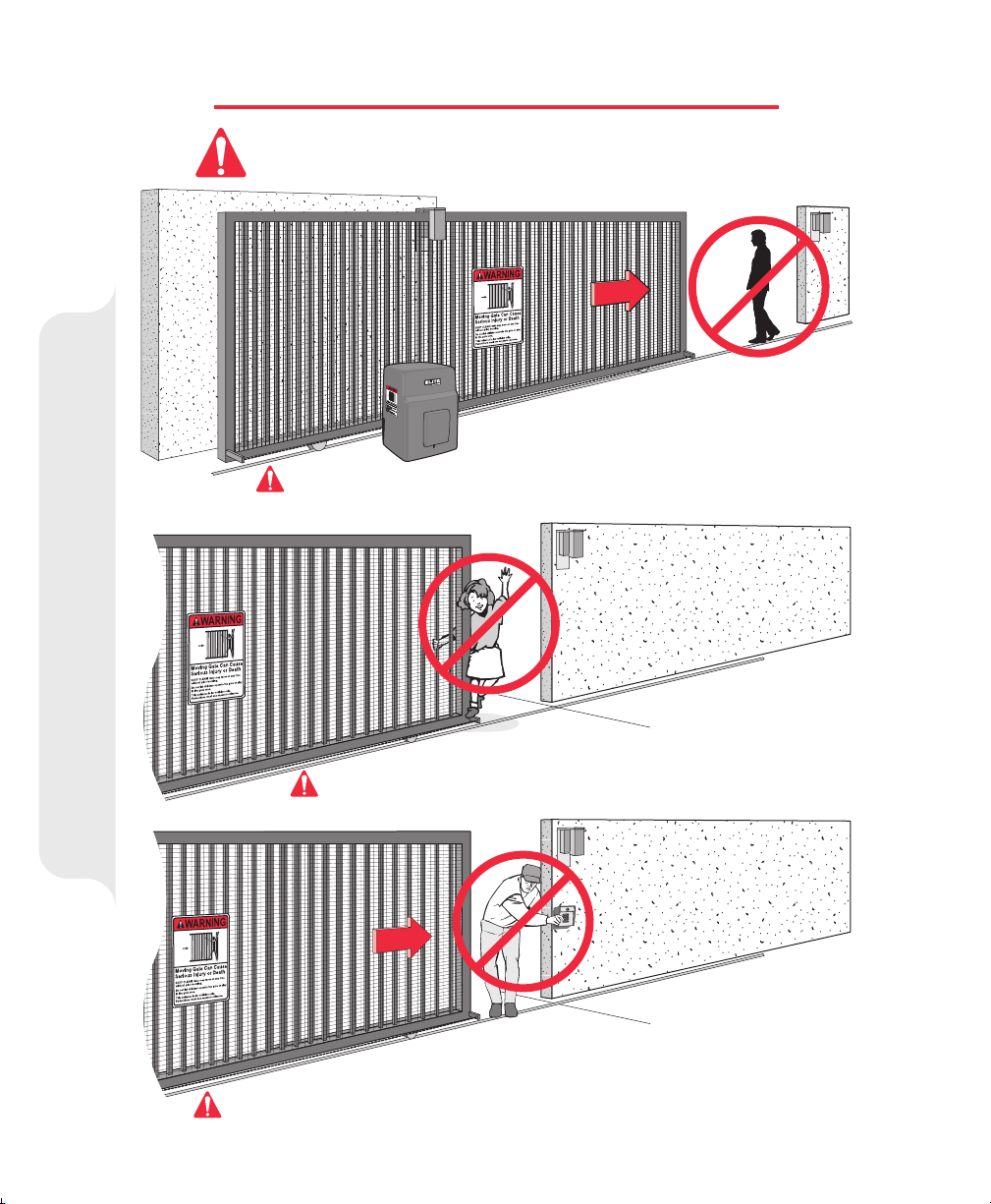
WARNINGS AND PRECAUTIONS
The SL3000UL™ Series is for Vehicular Gate Use Only!
NOT
for Use on Any Pedestrian: Passageways, Doorways or Gateways.
Property owners must never let pedestrians cross the path of a moving gate!
Property owners must never allow anyone to hang or ride on the gate!
Warnings and Precautions
Property owners must never mount any gate operating device near the gate's path!
10
Page 12
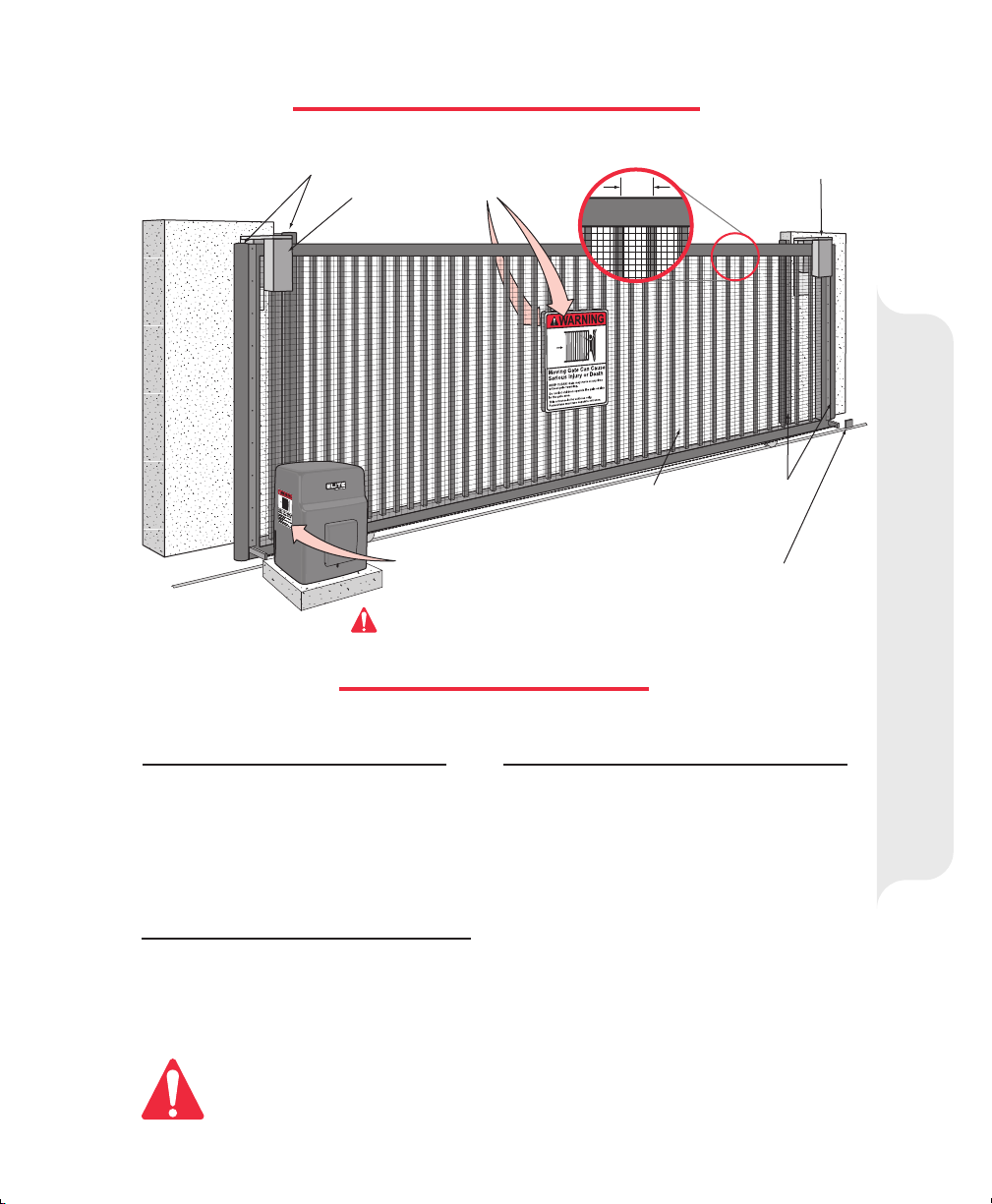
RECOMMENDED SETUP
Sensor Edges
Non-Pinch
Rollers
Warning Signs
Attached on
Both Sides
of Gate
Warning Sign Clearly
Visible on Operator
3" Max. Width of Pickets
Pedestrians Must have a Separate Walkway!
SPECIFICATIONS
(2"x 2" Screen)
Weld Physical Stops on
Both Ends of Gate Rail
Non-Pinch
Rollers
Setup and Specifications
Sensor
Edges
SL3000UL™, SL3000ULDC™
SL3000ULH™, SL3000ULDCH™
1/2 hp Motor, 120 Vac, 4 Amp.
Maximum Gate Length – 37 ft.
Maximum Gate Weight – 1000 lbs.
Maximum Pull – 105 lbs.
SL3000UL1HP™
SL3000UL1HPH™
Two 1/2 hp Motors, 120 Vac, 8.4 Amp.
Maximum Gate Length – 37 ft.
Maximum Gate Weight – 2000 lbs.
Maximum Pull – 180 lbs.
Be sure to read and follow all Chamberlain Elite and UL instructions before installing and
operating any Chamberlain Elite products. the Chamberlain Group, Inc is not responsible
for improper installations or failure to comply with local building codes.
SL3000ULDM™, SL3000ULDMDC™
SL3000ULDMH™, SL3000ULDMDCH™
Two 1/2 hp Motors, 120 Vac, 4.7 Amp.
Maximum Gate Length – 37 ft.
Maximum Gate Weight – 800 lbs.
Maximum Pull – 100 lbs.
DM
- Dual Motor
1HP
- One Horse Power
H
- Factory Installed Heater
DC
- Factory Installed DC2000 Backup System
11
Page 13
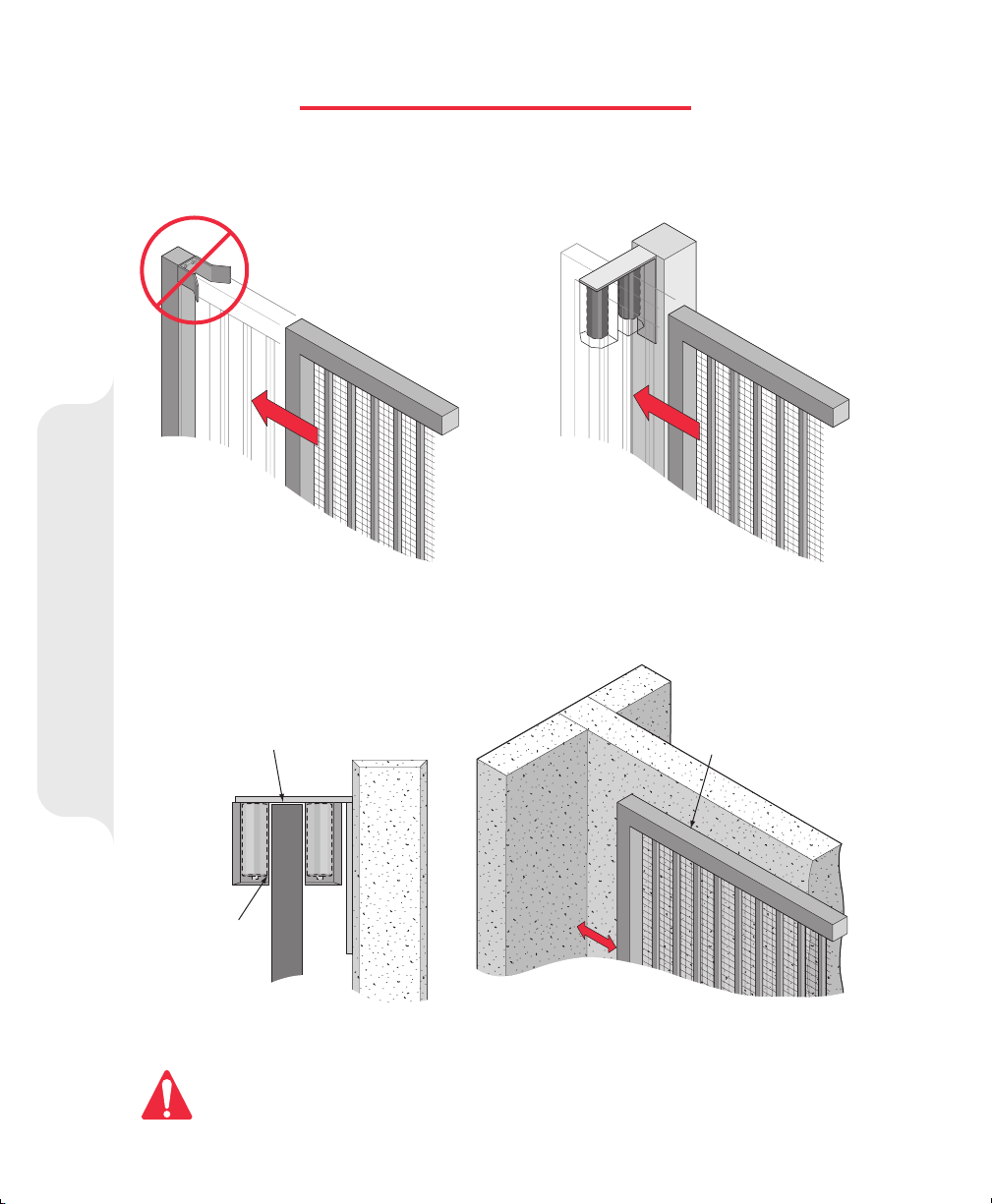
GATE POST WARNING
Because the coasting distance may vary due to changes in temperature, Elite does
installation of a stop or catch post in front of the gates path. To do so will cause the gate to hit the post in certain
instances.
NOT
recommend the
Incorrect Correct
Non-Pinch
Rollers
Important Notice!
Closing
Elite only recommends installation of catch rollers on the side of a catch post or wall with a minimal distance of
half an inch between the rollers and gate. Also when fully open the end of the sliding gate must stop at least five
inches from a wall.
Closing
1/4" Clearance from Top of Gate
Gate Post Warning
Non-Pinch
Rollers
1/2" Clearance
Between Gate
and Rollers
Gate in Fully
Opened Position
Wall
5"
Wall
Gate
For safety reasons, a physical stop must be installed on the gate prior to installation of the gate operator.
This will assure that the gate does not exceed movement limits and derail while opening or closing fully.
Minimum of 5" Clearance Between
Gate and Wall or Other Object
12
Page 14
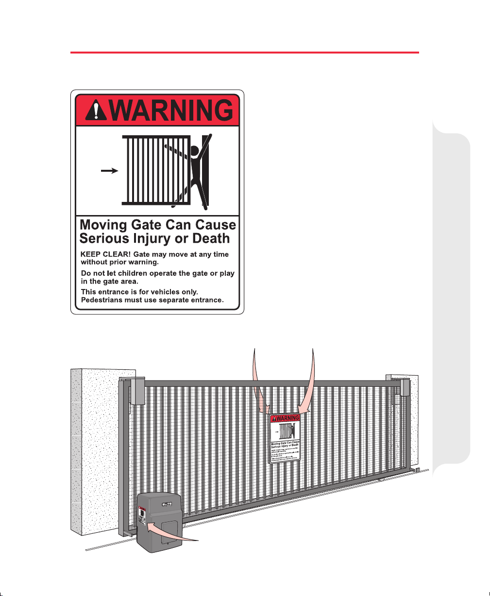
MOUNTING REQUIRED WARNING SIGNS
Installers are
UL required Warning Signs
view and on both sides of each gate installed. Each
sign is made with fastening holes in each corner and
should be permanently secured in a suitable manner.
Also the warning sticker should be placed on the
operator so it is clearly visible. Installers should keep
photos of signs on gate in their records.
Warning Signs Attached on Both Sides of Gate
required
to adhere to this procedure: The
must
be installed in plain
Important Notice!
Mounting Required Warning Signs
Warning Sign Clearly Visible on Operator
13
Page 15
TYPES OF INSTALLATION
It is highly recommended installing over-travel stops at both ends of the gate rail in any type of
installation, to prevent derailing.
Front Installation
Reason: Cost Efficient
Physical Stop
Physical Stop
Rear Installation
Reason: Chain is not visible
Physical Stop
Idler Wheel must have Safety Cover
Types of Installation
Ceiling Mount Installation
Reason: Space Efficient - Chain is not visible
Physical Stop
14
Page 16
17.5"
2"
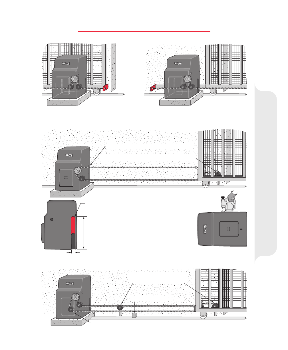
Cut the chain access slot on the one side
of the cover to the exact specifications.
Important: For safe operation of the gate
opener do not cut the slots any wider or longer
than shown. DO NOT modify the housing in any
way other than specified.
Make sure the idler wheel has a safety cover.
Cut the cover 17 1/2 inches high. (See below)
Rear Installation – Cover Modification
Use lower hole in chassis for the idler wheel.
Make sure additional idler
wheels have safety covers.
Over-Travel Stop
Weld front bracket with gate in open position. Weld rear bracket with gate in closed position.
CONNECTING THE CHAIN
Front Installation
Alternate Rear Installation – Lower Idler Wheel Position
Connecting the Chain
15
Page 17
CONCRETE PAD AND GATE ATTACHMENT
Top Inside View
Follow gate
manufacturers
8.25"
13"
specifications
and local
building codes
for setting post.
Conduit Area Without
Battery Back-Up
Suggested installation for dirt
ground. The measurements
depend on the type of ground.
(ie., asphalt, cement, dirt)
Check local building codes
before installation.
Above
Ground
Concrete (Reinforced Recommended)
6"
Below the
Frost Line
Check all
Local Codes
Concrete Pad
Optional Post
or
Mounting Plat
(See page 1
e
7
24"
)
Rear Installation
Cover over
Idler Wheel
12"
24"
Red Head Fastener
1/2" x 3 1/2"
Physical Stops on
Both Ends of Rail
12"
10"
8"
Concrete Pad and Gate Attachment
Front Installation
Physical Stops on
Both Ends of Rail
16
Page 18

GATE AND OPERATOR MOUNTING DISTANCE
4"
4" Minimum
Between Gate
and Sprocket
Correct Installation
OPTIONAL POST MOUNTING PLATE
Too Close
to Gate
Too High
Too Low
Incorrect Installation
Mounting Distance
Gate and Operator
Mounting Plate
Optional Post
Part # MPEL
3“ heavy steel posts are U-bolted to
mounting plate and cemented in ground.
Contact your local dealer
for more information.
Op
P
ional
t
duct
ro
Power and control
wiring can be run in
separate conduits.
17
Page 19

HOW TO CONNECT POWER (110V)
OnOn
O
Off
f
.
r
e
f
e
R
f
3
,
2
,
1
s
u
Do Not Use This Outlet Unless You Are
N
O
OFF
An Authorized Service Technician
Suggestion:
Seal all open holes
4
W
of electronic box
with sealant when
finished wiring.
F
N
F
O
O
B
O
Off
f
C
o
n
f
e
r
e
n
c
e
f
R
m
2
,
3
O
Off
C
o
n
f
e
f
r
e
n
c
e
f
R
o
o
m
1
Conference
Room 2
C
om
p
.
S
e
r
ve
2
Air (2)
Conditioner
C
o
m
p
.
S
e
rve
1
Minimum: 20-amp
breaker switch per
OffOff
OnOn
OnOn
OffOff
OnOn
OffOff
f
f
O
Off
operator needed.
Use U.L. Listed Conduit for
Supplying Power to the Unit
Black Wire (110 Vac)
Green Wire (Ground)
White Wire (Neutral)
Gate Operator MUST be Properly Grounded
Important: A factory installed heater must be wired into the power supply. See page 33.
Wire Gauge Requirement for 110 Vac Power Supply
16 Gauge
1/2 HP and Dual Motor
1 HP
Caution: Not responsible for conflicts between the information listed in the above chart and the requirements of your local building codes.
The information is for suggested use only. Check your local codes before installation.
150 Feet
75 Feet
14 Gauge
250 Feet
125 Feet
12 Gauge
400 Feet
200 Feet
10 Gauge
650 Feet
325 Feet
8 Gauge
1000 Feet
500 Feet
4 Gauge
2200 Feet
1100 Feet
Air (1)
Conditioner
Main
Room
SL-3000 (1)
SL-3000
(2
)
Eug. Dept.
Manu. 1 Rm
M
a
i
n
D
e
p
t
.
M
a
n
u
.
2
R
m
Earth Ground Rod Installation
Proper grounding gives an electrical charge, such as from an electrical static
discharge or a near lightning strike, a path from which to dissipate its energy safely
into the earth.
Without this path, the intense energy generated by lightning could be directed
towards the Elite gate operator. Although nothing can absorb the tremendous power
How to Connect Power 110V
of a direct lightning strike, proper grounding can protect the gate operator in most
cases.
Before digging more than 18" deep, contact local underground utility locating companies.
Avoid damaging gas, power, or other underground utility lines.
The earth ground rod must be located within 3 feet from the gate
operator.
The ground wire
Use the proper type earth ground rod for your local area.
must
be a single, whole piece of wire.
Never
splice two
wires for the ground wire. If you should cut the ground wire too short,
break it, or destroy its integrity, replace it with a single wire length.
Not responsible for improper installation or failure to comply with
all necessary local building codes.
18
12 gauge wire
8 ft
Page 20

POW
O
VE
Ground (-)
11
24 DC (+)
13
N
E
P
O
P
O
T
S
E
S
O
L
C
ER
RLOAD
S
M
A
D
E
IN
U
S
A
W4
A
B
G
K
IN
L
S
M
SURGE SUPPRESSOR TERMINAL INPUT CONNECTIONS
SAFETY EXIT
CENTER
SYSTEM
S
EN
SORS
R
M
O
R
S
A
N
L
1
E
A
S
ON
3
D
FIRE
D
E
N
S
DEPT.
A
S
E
M
C
M
O
O
R
C
P
EXIT
LOO
TIM
ER
60
3
1
E
R
S
O
FF
O
R
S
E
N
V
1
3
E
E
S
R
OPEN LEFT
STRIK
E
RADIO
O
PEN
RECEIVER
SAFETY
P
CENTER
LOO
P
LO
3
O
N
OPE
N RIGHT
Output Power
G
ATE
LO
CKED
RESET
OP
M
OT
O
R
GAB
GG
BB
AA
M/S LinkM/S Link
Page 22-23
G
B
A
Master/Second Operator
Page 40
3
4
External “Safety” Loop Detector
®
®
Page 45
11
Ground (-)
13
24 DC (+)
®
+24V
SENSING
COMMON
EDGE
INPUT
INFRARED
BLACK or BROWN
INFRARED
WHITE or BLUE
Photo Electric Sensors (Safety)
®
OmniControl Sur
1 65
43
2
Center
Center
Safety
Safety
Loop
Loop
Loop
Loop
3
4
ge Suppressor
Exit
Exit
Fire D
Fire D
ept
ept
Loop
Loop
Key Sw
Key Sw
itch
itch
P
P
/N
/N
Q
Q
4
4
1
1
0
0
P
P
a
a
te
te
n
n
t P
t P
e
e
n
n
d
d
in
in
g
Strike Open
Strike Open
Push Button
Push Button
g
++
––
R
R
adio
adio
R
R
eceiver
eceiver
7 1312111098
13
11
11
12
Remote NOT Included
Class 2
Class 2
Supply
Supply
o
V
4
o
2
V
4
2
++
24 Volt
––
Neg.
––
Neg.
Com.
10
10
C
D
s
C
l
t
D
s
l
t
DO NOT
let wire insulation
interfere with the removable
terminal connections.
Factory Installed
Radio Receiver
1
2
3
4
Page 27
Card
Reader
9
Push
Button
9
Surge Suppressor Terminal Connections
®
Page 40
5
6
External “Exit” Loop Detector
Important!
Terminals 11 and 12 are the only terminals that will Open and
Close with a single push of a button. All other terminals will only
open with a single push of a button.
19
Phone
10
9
Entry
1
2
3
4
5
6
7
8
9
H
E
L
P
0
Fire or
Any Key
Switch
8
7
Page 21

CHOOSING GATE MOVEMENT DIRECTION
Open to the RightOpen to the Left
OUT
OUT
IN
IN
MER
OFF
60
ON
13
Choosing Gate
OPEN LEFTOPEN LEFT
OPEN RIGHT
Movement Direction
RADIO
ADJUSTING GATE TRAVELING DISTANCE
Push Plate
Limit Nut
Lock Plate
CENTER SAFETY EXIT
W4
GB
A
MS LINK
CENTER SAFETY EXIT
SYSTEM ON
SENSORS
ALARM
SENSOR
MER
OFF
OPEN LEFT
ALARMSENSOR
DC-BACKUP
TIMER
POWER
60
3
OVERLOAD
13
ON
OFF
13
13
SENSOR
REVERSE
OPEN LEFT
FIRE
STRIKE
DEPT.
OPEN
COMMAND
PROCESSED
EXIT
SAFETY
LOOP
LOOP
MADE IN USA
OPEN
OPEN RIGHT
STOPCLOSE
GATE
RADIO
LOCKED
RECEIVER
CENTER
RESET
LOOP
MOTOR
OPEN RIGHTOPEN RIGHT
RADIO
60
ON
13
Nut
Adjusting Gate
Traveling Distance
Before Adjusting, Do the Following:
1. Turn the Power OFF!
2. Push the limit nut lock plate inward.
Roll the nut to the desired location.
Each notch is an estimated 1 inch of gate travel.
3. Place the plate back in a notch.
4. Turn the machine back on.
5. If you need more adjusting,
repeat the process.
20
Page 22

2-WAY ADJUSTABLE REVERSING SENSOR
Adjusted by Qualified Service Personnel
CENTER SAFETY EXIT
ALARMSENSOR
W4
GB
A
MS LINK
CENTER SAFETY EXIT
DO NOT
SYSTEM ON
SENSORS
13
13
ALARM
SENSOR
FIRE
DEPT.
COMMAND
PROCESSED
EXIT
LOOP
TOUCH ALARM SENSOR
DC-BACKUP
TIMER
POWER
60
3
OVERLOAD
13
ON
OFF
SENSOR
REVERSE
OPEN LEFT
STRIKE
RADIO
OPEN
RECEIVER
SAFETY
CENTER
LOOP
LOOP
MADE IN USA
OPEN
OPEN RIGHT
STOPCLOSE
GATE
LOCKED
RESET
MOTOR
CAUTION: If the power supply to the gate
operator is less than 99 volts, adjust the
alarm by turning the alarm adjustment
counter-clockwise enough to actuate the
alarm when obstructed but not sensitive
enough for false triggering to occur.
ADJUSTABLE TIMER
CENTER SAFETY EXIT
Maximum
Sensitivity
3
13
The level of reverse sensitivity depends on the
weight of the gate and the condition of
installation. To make a better gate system, use
SENSOR
REVERSE
Minimum
Sensitivity
any of Chamberlain Elite's power wheels.
Too sensitive = if the gate stops or reverses by itself.
Not sensitive enough = if the gate hits a vehicle and does not stop
or reverse.
Timer ON
TIMERTIMER
OFF
NSOR
OPEN LEFT OPEN RIGHT
60
ONON
3
13
Set Timer
1 to 60 seconds
Reversing Sensor
2-Way Adjustable
Adjustable Timer
ALARMSENSOR
W4
GB
A
MS LINK
CENTER SAFETY EXIT
SYSTEM ON
SENSORS
ALARM
SENSOR
13
13
FIRE
DEPT.
COMMAND
PROCESSED
EXIT
LOOP
Timer can be set from 1 to 60 seconds (Timer ON),
OR for push open/push close type operation (Timer OFF).
DC-BACKUP
TIMER
POWER
60
3
OVERLOAD
13
ON
OFF
SENSOR
REVERSE
OPEN LEFT
STRIKE
RADIO
OPEN
RECEIVER
SAFETY
CENTER
LOOP
LOOP
MADE IN USA
OPEN
OPEN RIGHT
STOPCLOSE
GATE
LOCKED
RESET
MOTOR
TIMERTIMER
OFFOFF
NSOR
OPEN LEFT OPEN RIGHT
60
ON
3
13
Timer OFF
Note: When using master/second gates, the gate that takes the longest to open should be set as the master.
21
Page 23

MASTER/SECOND WITH TIMER ON
TIMER
ON
TIMER
ON
Master and Second Boards are InterchangeableMaster Omni Board Primary Control for System
Caution: Never run high voltage and low voltage wires in same conduit
Use low voltage wires in separate conduit to connect gate operators together
Note: The gate that takes the longest to open should be set as the master.
CENTER SAFETY EXIT
Master Omni Board
TIMER
60
3
ALARMSENSOR
W4
GB
A
MS LINK
CENTER SAFETY EXIT
SYSTEM ON
SENSORS
13
13
ALARM
SENSOR
FIRE
DEPT.
COMMAND
PROCESSED
EXIT
LOOP
®
O
C
C
e
e
GG
BB
AA
L
L
n
k
L
i
S
/
M
n
k
L
i
S
/
M
re
p
p
u
S
e
g
r
u
l S
tro
n
o
iC
n
m
n
n
te
te
r
r
S
S
a
a
f
f
e
e
t
t
y
y
E
E
x
x
i
i
F
F
t
t
i
i
r
r
e
e
D
D
e
e
p
p
t
t
o
o
o
o
p
p
L
L
o
o
o
o
p
p
L
L
o
K
K
o
o
e
e
o
p
y
y
p
S
S
w
w
it
it
c
c
h
h
DC-BACKUP
TIMER
OFF
SENSOR
REVERSE
OPEN LEFT
STRIKE
OPEN
SAFETY
LOOP
r
so
s
S
S
t
t
r
r
ik
ik
e
e
P
P
u
u
s
s
h
h
B
B
POWER
60
3
OVERLOAD
13
ON
MADE IN USA
OPEN
OPEN RIGHT
STOPCLOSE
GATE
RADIO
LOCKED
RECEIVER
CENTER
RESET
LOOP
MOTOR
P
P
/
/
N
N
Q
Q
4
4
1
1
0
0
P
P
a
a
t
t
e
e
n
n
t
t
P
P
e
e
n
n
d
d
i
i
n
n
g
g
++
––
s
2
l
s
a
C
s
2
l
s
a
C
S
u
p
p
l
y
S
u
p
p
l
y
O
O
p
p
e
e
n
n
R
R
a
a
d
d
io
io
D
V
o
l
s
C
t
4
D
2
V
o
l
s
C
t
4
2
u
u
t
t
t
t
o
o
R
R
n
n
e
e
c
c
e
e
iv
iv
e
e
r
r
OFF
NSOR
OPEN LEFT OPEN RIGHT
Master Timer “ON”
Use Shielded Twisted Wires
to Connect the Surge
Suppressor of each
Gate Operator Together
g
g
din
din
10
10
4
4
en
en
Q
Q
t P
t P
/N
/N
P
CHASSIS
GROUND
P
Center
Center
AA
BB
aten
aten
GG
P
P
Loop
Loop
k
k
n
n
i
i
L
L
S
S
/
/
M
M
Master / Second with Timer ON
1. Connect G from the master surge suppressor to G of the second surge
suppressor.
2. Connect B from the master surge suppressor to B of the second surge
suppressor.
3. Connect A from the master surge suppressor to A of the second surge
suppressor.
4. Turn timers on BOTH Omni boards to the “ON” position
5. Turn the SECOND Timer adjustment all the way Counterclockwise
6. Use MASTER timer ONLY to select the desired time
ON
CHASSIS
GROUND
13
g
g
in
in
0
0
d
d
1
1
4
4
en
en
Q
Q
t P
t P
n
n
/N
/N
P
P
AA
BB
ate
ate
GG
P
P
k
k
n
n
i
i
L
L
S
S
/
/
M
M
Adjust Time Desired
0 to 60 seconds
Second Omni Board
CENTER SAFETY EXIT
W4
GB
A
MS LINK
CENTERSAFETY EXIT
®
t
n
o
iC
n
m
O
C
e
r
e
n
t
C
e
r
e
n
t
S
S
a
a
f
f
GG
BB AA
L
o
o
p
L
o
o
p
L
L
o
o
k
n
i
L
S
k
n
/
i
L
M
S
/
M
Center
Center
Loop
Loop
MAXIMUM
Counterclockwise
Setting
TIMER
OFF
NSOR
OPEN LEFT OPEN RIGHT
ON
Second Timer “ON”
SYSTEM ON
SENSORS
ALARM
r
y
y
e
e
t
t
o
o
p
p
13
13
SENSOR
FIRE
DEPT.
COMMAND
PROCESSED
EXIT
LOOP
u
S
e
g
r
u
S
l
o
t
i
E
x
t
i
E
x
e
e
r
r
i
i
F
F
L
o
o
p
L
o
o
p
y
y
K
K
e
e
60
TIMER
60
3
13
ON
OFF
SENSOR
REVERSE
OPEN LEFT
OPEN RIGHT
GATE
STRIKE
RADIO
LOCKED
OPEN
RECEIVER
SAFETY
CENTER
RESET
LOOP
LOOP
MOTOR
P
P
/
/
N
N
Q
Q
4
4
1
1
0
0
r
o
s
s
e
r
p
p
P
P
a
a
t
t
e
e
n
n
t
t
P
P
e
e
n
n
d
d
i
i
n
n
g
g
++
––
l
l
C
C
a
a
S
S
u
u
p
p
p
p
e
e
D
t
D
t
n
e
p
n
O
e
p
t
e
O
i
r
k
S
t
e
i
r
k
S
o
R
i
d
o
a
R
i
d
a
o
V
4
2
o
V
4
2
c
c
h
h
t
t
i
i
S
S
w
w
n
o
n
o
t
t
s
P
u
t
h
B
u
s
P
u
t
h
B
u
R
c
i
e
e
v
R
c
e
i
e
e
v
e
r
r
3
13
ALARMSENSOR
DC-BACKUP
POWER
OVERLOAD
MADE IN USA
OPEN
STOPCLOSE
s
s
s
s
2
2
p
p
l
l
y
y
D
C
D
s
l
C
t
s
l
t
22
Page 24

MASTER/SECOND WITH TIMER OFF
TIMER
OFF
TIMER
OFF
Caution: Never run high voltage and low voltage wires in same conduit
Use low voltage wires in separate conduit to connect gate operators together
Master Omni Board Second Omni Board
CENTER SAFETY EXIT
CENTER SAFETY EXIT
Master / Second with Timer OFF
TIMER
ALARMSENSOR
W4
GB
A
MS LINK
CENTERSAFETY EXIT
SYSTEM ON
SENSORS
13
ALARM
SENSOR
COMMAND
®
S
l
o
r
t
n
o
C
i
n
m
O
C
e
r
e
n
t
C
e
r
e
n
t
y
y
S
S
e
e
t
t
a
a
f
f
GG
BB AA
L
o
o
p
L
o
o
p
L
L
o
o
o
o
p
p
k
n
i
L
S
k
n
/
i
L
M
S
/
M
DC-BACKUP
TIMER
POWER
60
3
OVERLOAD
13
ON
OFF
REVERSE
OPEN
LOOP
s
SENSOR
o
s
S
S
t
t
i
i
r
r
s
s
P
P
u
u
OPEN LEFT
RADIO
RECEIVER
CENTER
LOOP
P
P
r
P
P
a
a
t
t
e
e
n
n
t
t
––
O
n
O
n
e
e
p
p
k
k
e
e
n
n
o
o
t
t
t
t
h
h
B
B
u
u
OPEN RIGHT
GATE
LOCKED
RESET
MOTOR
/
/
N
N
Q
Q
4
4
1
1
0
0
P
P
e
e
n
n
d
d
in
in
g
g
++
i
d
o
a
R
i
d
o
a
R
r
e
v
i
e
r
c
e
e
v
R
i
e
c
e
R
MADE IN USA
OPEN
STOPCLOSE
l
l
s
s
s
s
2
2
C
C
a
a
S
S
y
y
u
u
p
p
p
p
l
l
D
C
D
s
l
C
o
t
V
4
s
2
l
o
t
V
4
2
13
FIRE
STRIKE
DEPT.
PROCESSED
EXIT
SAFETY
LOOP
e
r
p
p
u
S
e
g
r
u
t
t
i
i
E
E
x
x
t
p
e
D
e
t
r
p
e
i
F
D
e
r
i
F
L
L
o
o
o
o
p
p
h
c
t
i
S
w
h
y
K
e
c
t
i
S
w
y
K
e
OFF
NSOR
OPEN LEFT OPEN RIGHT
60
ON
3
13
ALARMSENSOR
W4
GB
A
MS LINK
CENTERSAFETY EXIT
SYSTEM ON
SENSORS
13
ALARM
SENSOR
COMMAND
PROCESSED
®
r
u
S
l
o
r
t
n
o
iC
n
m
O
C
e
r
e
n
t
C
e
r
e
n
t
y
y
S
S
e
e
t
t
a
a
f
f
E
E
x
x
GG
BB AA
L
o
o
p
L
o
o
p
L
L
o
o
o
o
p
p
L
L
o
o
o
o
k
n
i
L
S
k
n
/
i
L
M
S
/
M
DC-BACKUP
TIMER
POWER
60
3
OVERLOAD
13
ON
OFF
13
FIRE
STRIKE
DEPT.
OPEN
EXIT
SAFETY
LOOP
LOOP
s
e
r
p
p
u
S
e
g
t
t
i
i
t
p
e
t
D
p
e
e
D
r
i
e
F
r
i
F
p
p
c
h
t
c
i
S
w
h
y
t
K
e
i
S
w
y
K
e
MADE IN USA
SENSOR
OPEN
REVERSE
OPEN LEFT
OPEN RIGHT
STOPCLOSE
GATE
RADIO
LOCKED
RECEIVER
CENTER
RESET
LOOP
MOTOR
P
P
/
/
N
N
Q
Q
4
4
1
1
0
0
r
o
s
P
P
a
a
t
t
e
e
n
n
t
t
P
P
e
e
n
n
d
d
in
in
g
g
++
––
2
2
l
l
s
s
s
s
C
C
a
a
S
S
u
u
p
p
p
p
l
l
y
y
n
e
p
O
k
e
i
r
S
t
n
e
p
O
k
e
i
r
S
t
o
i
d
o
a
i
R
d
a
R
C
D
s
l
C
o
t
V
D
s
l
o
t
V
4
2
4
2
n
o
t
B
u
t
h
s
n
P
u
o
t
B
u
t
h
s
P
u
v
r
c
e
i
e
e
v
R
r
c
e
i
e
e
R
Use Shielded Twisted Wires
to Connect the Surge
Suppressor of each
Gate Operator Together
g
CHASSIS
GROUND
ing
ing
0
0
1
1
4
4
end
end
Q
Q
t P
t P
/N
/N
P
P
Center
Center
AA
aten
aten
GG BB
P
P
Loop
Loop
k
k
n
n
i
i
L
L
S
S
/
/
M
M
CHASSIS
GROUND
g
in
in
0
0
d
d
1
1
4
4
en
en
Q
Q
t P
t P
n
n
/N
/N
P
P
ate
ate
GG BB
P
P
n
n
i
i
L
L
S
S
/
/
M
M
Center
Center
AA
Loop
Loop
k
k
TIMER
OFF
NSOR
60
ON
3
13
OPEN LEFT OPEN RIGHT
1. Connect G from the master surge suppressor to G of the second surge suppressor.
2. Connect B from the master surge suppressor to B of the second surge suppressor.
3. Connect A from the master surge suppressor to A of the second surge suppressor.
4. Turn timers on BOTH Omni boards to the “OFF” position
PARTIAL MASTER/INDIVIDUAL CONTROL
In order for the following operation to occur, follow the instructions.
Example: There is a double gate, the entry gate is to be opened with a radio transmitter and the exit gate with a
free exit loop. Only one safety loop system is to open both gates, and a fire department switch should open both
gates at the same time.
1. Connect the radio receiver to entry gate only.
2. Connect the exit loop to exit gate only.
3. Connect the safety loop to both entry and exit gates. (Observe polarity of voltage)
4. Connect the fire department switch to both entry and exit gates. (Observe polarity of both operators)
23
Page 25

BUILT-IN RESET BUTTON
When the gate operator’s audio alarm (See next page) has been tripped, the
operator to function again.
Built-In Reset Button
The
Reset Button
If the audio alarm goes off, always check the gate area for:
Pressing the
operator does
will shut off an activated audio alarm and reset the operator to function again.
• Obstructions in the gate path.
• Damage to the gate and/or gate operator.
Reset Button
NOT
will
stop
need to be reset after doing this.
a moving gate during a normal open/close cycle, like a stop button. The
24
Reset Button
must be pushed for the
Page 26

REMOVE CONTROL BOARD
N
FF
FF
ON
O
O
O
Control Board
W4
4
W
Disconnect wire harnesses from OmniControl board. Unscrew 3 nuts and remove board.
AUDIO ALARM
When one of the following events happens
the Alarm will Sound for 5 minutes!
Press the Built-In Reset Button to Shut Off Alarm
1
The gate is too heavy.
and Reset Operator!
(See previous page)
Twice Consecutively,
Remove
Audio Alarm
2
Debris is on the gate's track such as
mud, rocks, dirt, etc.
4
The gate has one or more broken
wheels.
25
3
The gate is hitting a wall or vehicle.
5
A moving vehicle has hit the gate and
the wheel is off the track.
Page 27

SOLENOID/MAGLOCK J3 CONNECTION
J3J3
1
3
Normally Closed
5
7
Common
9
CENTER SAFETY EXIT
2
4
6
8
10
ALARMSENSOR
W4
GB
A
MS LINK
CENTER SAFETY EXIT
2
4
6
8
10
SYSTEM ON
SENSORS
13
ALARM
SENSOR
1
3
5
7
9
COMMAND
13
SENSOR
REVERSE
FIRE
STRIKE
DEPT.
OPEN
PROCESSED
EXIT
SAFETY
LOOP
LOOP
J3J3
DC-BACKUP
TIMER
OPEN LEFT
OFF
RADIO
RECEIVER
CENTER
LOOP
ON
60
OPEN RIGHT
13
GATE
LOCKED
RESET
MOTOR
POWER
3
OVERLOAD
MADE IN USA
OPEN
STOPCLOSE
Solenoid Lock
#3 Normally Closed
#7 Common
Insert 2 supplied wires
into J3 plug (#3 and #7)
(Motor Harness)
Connection of a Solenoid or Magnetic Lock can be made
using the J3 plug and three wires supplied with the unit.
Solenoid Lock
Ground
Wire Nut
Power
Ground
Magnetic Lock
Solenoid / Maglock J3 Connection
2
4
6
8
10
J3J3
1
3
5
7
9
Insert 2 supplied wires
into J3 plug (#7 and #8)
(Motor Harness)
#7 Common
#8 Normally Open
Ground
Wire Nut
Power
Ground
Normally Open
Relay Contact Rating
0.5 A - 125 Vac
1 A - 24 VDC
Plug-In
Transformer
Magnetic
Lock
Plug-In
Transformer
26
Page 28

RADIO RECEIVER PROGRAMMING
Note: Hand Held
NOT
Remote
with Gate Operator.
Up to 31 Security Plus, Passport
remotes or unlimited dip switch
remotes can be used.
Programming Radio Receiver:
Press and
Within that time, press a desired button on your hand held remote for
to program the radio receiver.
Repeat
Release
the “Learn Button”. LED will light for 30 seconds.
this process for every hand held remote to be used with the gate operator.
Erase ALL Remote Control Codes:
Press and
now erased.
Hold
the “Learn Button” until LED turns off (6 seconds).
Included
3 seconds
All
codes are
Radio Receiver Programming
Mini 3 Button
Part #
970LM
Optional
Part #
Part #
Part #
Part #
Hand Held Remotes
971LM
972LM
Op
Part #
Part #
ional
t
CPT1
CPT2
Products
973LM
974LM
27
Part #
Part #
CPT3
CPT4
Mini 3 Button
Part #
CPTK3
Mini 3 Button with
HID Prox. Sensor
Part #
CPTK3PH
Page 29

EMERGENCY RELEASE
Allen wrench
drill bit size is 5/16"
Crank Tool
Turn the power
OFF!
Push
the crank tool in hole. Safety releases will separate. Turn the crank to open the gate.
Push In
Note:
You may use a cordless
power drill (6”/sec) for quicker
opening in non-emergency
situations.
Emergency Release
28
Page 30

OPTIONAL EMERGENCY RELEASE
Fire Release Box
Part # CP17
Turn the power OFF to the gate operator
and unlock the fire box.
Optional Emergency Release
Op
roduct
P
ional
t
Pull firmly on the “T” Handle
to release the chain.
The chain is held in place by a spring loaded pin.
For More Details,
ask your Local Dealer
29
Page 31

OPTIONAL FACTORY INSTALLED DC2000
Plug in the 12 pin plug into the DC2000 control unit. Make sure the “System ON” and “Charge OK” LEDs are
1
lit. If the “Battery Low” led comes on, the battery needs to charge before it can be used.
2
Make sure “Gate Direction” setting on DC2000 is set the same as the gate operator's setting.
ional
t
Op
duct
ro
P
CLASS I, II, III, IV
s
s
e
n
r
a
H
0
0
0
2
C
D
DO NOT wire 110 Vac power to the DC2000
Important: All devices
wired to the DC2000
be dedicated to it alone.
Normal operation will be
controlled by separate
devices wired to the
OmniControl™ board.
Socket
6
5
4
3
2
1
Motor Safety Wires
DO NOT Remove
System Setup
“Manual” setting: The DC2000 will respond to the input devices wired to the J 20 socket.
This mode can also be used as an emergency override. If 110 Vac power is on, but the system has an electronic
malfunction, the gate can be operated using the DC2000 system with input devices wired to J 20 socket.
“Auto” setting: The DC2000 opens the gate automatically upon 110 Vac power failure and stays open. When 110
Optional Factory Installed DC2000
Vac power is restored, the gate operator will return to normal operation. (The gate can be closed by manual
command)
MUST
7
Manual
Mode
Auto
Mode
110 Vac Power
Failure
Push and Hold to
operate gate
Gate automatically
opens
110 Vac Power On,
OmniControl™ Board Malfunction
Turn the 110 Vac power off then
push and Hold to operate gate
Turn the 110 Vac power off then gate
opens automatically
30
110 Vac Power On,
Emergency Override
Push and Hold to override
the OmniControl™ board
Push and Hold to override
the OmniControl™ board
Page 32

WIRING OPTIONAL DC2000 DEVICES
Important: All devices wired to the DC2000 MUST be dedicated to it alone. Normal operation will be
controlled by separate devices wired to the OmniControl™ board.
If the DC2000 is automatically opening the gate due to a power failure, any manual command such as
“One-Button”, “Three Push Button”, “Key Switch”, “Photo Beam” or “Edge Sensor” will cancel the automatic
mode of the DC2000. After such cancellation, the DC2000 will continue to operate in manual mode until 110 Vac
power is restored.
Manual One-Button
76
5
4
3
2
1
DO Not Remove the
2 Factory Installed
Wires in the
J 20 Socket
ional
t
Op
Products
Part #
AEXITP
Push and
“Hold”
Push again and
to Open
“Hold”
to Close
Wiring Optional DC2000 Devices
Key Switch
1
EMERGENCY OVERRIDE
If 110 Vac power is on, but the
system has an electronic
malfunction, the gate can be
operated using the DC2000
system with
devices shown.
ANY
of these
76
5
4
3
2
Part #
A1KX
Turn and
Turn again and
“Hold”
to Open
“Hold”
to Close
Radio Receivers
76
5
4
3
2
1
12 V
6
5
4
4
Jumper P2:
to Momentary (M)
Jumper P3:
to 12 Volt
1
2
3
4
Three-Button
76
5
4
3
2
1
N.O.
3
N.O.
2
N.O.
1
Com
Com
Com
12 VDC Radio Receiver
Back-Up Operation Only
Part #
412HM
4
Button Two:
Back-Up
Operation
4
(DC2000)
4
Normal Gate Operation
to OmniControl
board
Button Three:
Optional Accessories
®
24 VDC radio receiver to be
used by OmniControl™
Board ONLY
Button One:
Normal Gate Operation
(OmniControl™ Board)
3 Push Button
Part #
02-103
Push and
“Hold”
a Button to operate
Push and
“Hold”
Push again and
31
DC2000 Transmitter Button to Open
“Hold”
DC2000 Transmitter Button to Close
Page 33

CENTER SAFETY EXIT
CENTER SAFETY EXIT
FIRE
DEPT.
13
STRIKE
OPEN
RADIO
RECEIVER
TIMER
SYSTEM ON
EXIT
LOOP
ALARM
SENSOR
REVERSE
SENSOR
OPEN
STOPCLOSE
SAFETY
LOOP
CENTER
LOOP
GATE
LOCKED
60
POWER
OVERLOAD
OFF
W4
OPEN LEFT
DC-BACKUP
ALARMSENSOR
OPEN RIGHT
3
SENSORS
RESET
MOTOR
13
13
COMMAND
PROCESSED
ON
GB
MS LINK
A
MADE IN USA
CLASS I, II, III, IV
1
3
2
7
6
5
4
Part #
AOMRON12V
WIRING OPTIONAL DC2000 SAFETY DEVICES
Edge Sensor
UL Listed 3 Sided Sensor
OmniControl™ Board
Sensor Connection
P
O
W
E
R
O
V
E
R
L
O
A
D
D
C
-B
A
C
K
U
P
ALARM
SENSOR
USE ONLY 12 VDC FAILSAFE PHOTO BEAM SENSORS
FOR THIS SAFETY OPTION
Failsafe Photo Beam: If a photo beam is not working, loses
power or photo beam is blocked, then the photo beam will
stop all gate operation.
Photo Beam Sensor
12 VDC
Power +12 VDC
Power Ground
Important:
DO NOT
remove any existing
attached wires from the
Sensor/Alarm connector.
Wiring Optional DC2000 Safety Devices
DO Not Remove the
2 Factory Installed Wires
in the J 20 Socket
Contact your local dealer
for more information.
4
6
Part #s
G65MGO20
G65MGR20
G65MGS20
Op
t
ional
Products
32
Page 34

OPTIONAL FACTORY INSTALLED HEATER
TOUCH
DON’T
Connect the black, white and ground wire from the heater to the 110 Vac power supply as shown. When the
heater switch is left in the “ON” position, the heater will turn on and off automatically when needed.
Switch should
remain in the
“ON” position.
4
W
Power Supply
(110 Vac)
N
FF
O
O
S
L
P
o
Gr
White N
Bla
C
e
e
AUT
c
n Gro
k
120 VAC
eu
und
ION
t
ral
DON’T
TOUCH
Heater may be
HOT when the
switch is “ON”!
ional
t
Op
duct
ro
P
Green Wires
w
e
r
W
i
r
e
s
(Ground)
Black Wires
(110 Vac)
Optional Factory Installed Heater
33
White Wires
(Neutral)
Page 35

Q
C
C
A
B
O
P
E
N
S
T
O
P
C
L
O
S
EM
A
G
L
O
C
K
A
L
A
R
M
A
R
M
E
D
M
/S
L
IN
K
+
QCC Access Socket
+
QCC Access ID (Top Positive)
Q
C
C
A
B
O
PEN STO
P
CLO
SE
M
AGLO
CK ALARM
ARM
ED
M
/S
LINK
Mode of Operation Switch
CENTER SAFETY EXIT
CENTER SAFETY EXIT
FIRE
DEPT.
13
STRIKE
OPEN
RADIO
RECEIVER
TIMER
SYSTEM ON
EXIT
LOOP
ALARM
SENSOR
REVERSE
SENSOR
OPEN
STOPCLOSE
SAFETY
LOOP
CENTER
LOOP
GATE
LOCKED
60
POWER
OVERLOAD
OFF
W4
OPEN LEFT
DC-BACKUP
ALARMSENSOR
OPEN RIGHT
3
SENSORS
RESET
MOTOR
13
13
COMMAND
PROCESSED
ON
GB
MS LINK
A
MADE IN USA
QCC
AB
OPEN STOP CLOSE MAGLOCK ALARM
ARMED
M/S LINK
QCC
AB
OPEN STOP CLOSE MAGLOCK ALARM
ARMED
M/S LINK
2 3 4 5 6 7 8 9 10 11 12 13 14 15116
QCC socket with QCC access ID inserted
QCC “Mode of Operation” switch
Omni Option Board Part # OOMNIEXB
QCC Access ID Part # OQCCOMNI
Gnd
Gnd
Gnd
Gnd
Gnd
B
A
N.O.
N.O.
N.O.
N.O.
N.C.
N.C.
N.C.
Com
Com
QCC is designed for slide gate operators only!
OPTIONAL OMNI OPTION BOARD DESCRIPTION
OPTIONAL QCC (QUICK CLOSE CIRCUIT)
Optional Omni Option
Board Description
Optional QCC
Quick Close Circuit
– Open Command
– Stop Command
– Close Command
– Common
– Normally Closed
– Normally Open
Maglock
1
& 2
3 & 4
5 & 6
7
8
9
Master/
Second
or
RS485
– Burglar Alarm Output
– Burglar Alarm Input
– Ground
– B
– A
10
& 11
12
& 13
14
15
16
Solenoid
Op
t
ional
P
ro
duct
Op
t
ional
Products
Omni Option Board
Part # OOMNIEXB
Mode A (switch OFF)
If the gate is closing while a car is driving over the safety loop, the QCC will stop the gate
for a second then open the gate while the car is over the safety loop detector. As soon as the car leaves the safety
loop, the QCC will resume closing the gate.
Mode B (switch ON)
If the gate is closing, and a vehicle drives over the safety loop, the QCC will stop the gate. It will not open the gate.
After the vehicle leaves the safety loop, the QCC will close the gate.
The QCC can operate in two different modes. The mode of operation will depend
on the switch setting on the Omni Option Board.
34
Page 36

OPTIONAL HOUSE ALARM/PROXIMITY SWITCH WITH OMNI OPTION BOARD
Omni Option Board
Part # OOMNIEXB
CENTER SAFETY EXIT
QCC
W4
AB
OPEN STOP CLOSE MAGLOCK ALARM
M/S LINK
GB
A
ARMED
MS LINK
CENTER SAFETY EXIT
SYSTEM ON
SENSORS
13
13
ALARM
SENSOR
FIRE
DEPT.
COMMAND
PROCESSED
EXIT
LOOP
QCC
AB
OPEN STOP CLOSE MAGLOCK ALARM
ARMED
M/S LINK
10 11 12 13
ALARMSENSOR
DC-BACKUP
TIMER
POWER
60
3
OVERLOAD
13
OFF
ON
MADE IN USA
SENSOR
OPEN
REVERSE
OPEN LEFT
OPEN RIGHT
GATE
STRIKE
RADIO
LOCKED
OPEN
RECEIVER
SAFETY
CENTER
RESET
LOOP
LOOP
MOTOR
Use Low Voltage
STOPCLOSE
Wire 20 AWG
Alarm
10 – Common
11 – Normally Open
Armed
12 – Normally Closed
13 – Ground
OmniControl™ Board
12VDC
House Alarm System
Dry Contact
2"
M
ax
.
ional
t
House Alarm
Op
Products
Proximity Switch
Part # APRS
OPTIONAL MASTER / SECOND WITH OMNI OPTION BOARD
Omni Option Board
Part # OOMNIEXB
ED
M/S LIN
M/S L IN K
Optional House Alarm /Proximity
Switch with Omni Option Board
Optional Master / Second
with Omni Option Board
CENTER SAFETY EXIT
QCC
W4
AB
GB
A
MS LINK
OPEN STOP CLOSE MAGLOCK ALARM
CENTER SAFETY EXIT
BAG
ALARMSENSOR
DC-BACKUP
ARMED
SENSORS
ALARM
13
SENSOR
SYSTEM ON
M/S LINK
COMMAND
PROCESSED
FIRE
DEPT.
EXIT
LOOP
13
TIMER
OFF
SENSOR
REVERSE
OPEN LEFT
STRIKE
RADIO
OPEN
RECEIVER
SAFETY
CENTER
LOOP
LOOP
60
ON
OPEN RIGHT
LOCKED
MOTOR
13
GATE
RESET
POWER
3
OVERLOAD
MADE IN USA
OPEN
STOPCLOSE
Use this socket (M/S LINK) if the Omni
Option Board is being used, and
Master/Second option is needed.
Op
ro
P
ional
t
duct
35
Page 37

OPTIONAL SOLENOID CONNECTION WITH OMNI OPTION BOARD
7 – Common
8 – Normally Closed
SE MAGLOCKMAGLOCK AL
9 – Normally Open
CENTER SAFETY EXIT
ALARMSENSOR
60
13
ON
OPEN RIGHT
RADIO
GATE
RECEIVER
LOCKED
CENTER
RESET
LOOP
MOTOR
0.5 A - 125 Vac
1 A - 24 VDC
DC-BACKUP
POWER
3
OVERLOAD
MADE IN USA
OPEN
STOPCLOSE
QCC
W4
AB
GB
A
MS LINK
OPEN STOP CLOSE MAGLOCK ALARM
with Omni Option Board
CENTER SAFETY EXIT
ARMED
Optional Solenoid Connection
Omni Option Board
M/S LINK
Op
SYSTEM ON
SENSORS
ALARM
SENSOR
P
13
13
FIRE
STRIKE
DEPT.
OPEN
COMMAND
PROCESSED
EXIT
SAFETY
ional
LOOP
LOOP
t
roduct
TIMER
OFF
SENSOR
REVERSE
OPEN LEFT
Relay Contact Rating
Part # OOMNIEXB
OPTIONAL MAGLOCK CONNECTION WITH OMNI OPTION BOARD
SE MAGLOCKMAGLOCK AL
CENTER SAFETY EXIT
Solenoid Lock
7
8
9
Ground
Plug-In
Transformer
Power
Ground
7 – Common
8 – Normally Closed
9 – Normally Open
ALARMSENSOR
60
13
ON
OPEN RIGHT
RADIO
GATE
RECEIVER
LOCKED
CENTER
RESET
LOOP
MOTOR
0.5 A - 125 Vac
1 A - 24 VDC
DC-BACKUP
POWER
3
OVERLOAD
MADE IN USA
OPEN
STOPCLOSE
QCC
W4
AB
GB
A
MS LINK
OPEN STOP CLOSE MAGLOCK ALARM
with Omni Option Board
CENTER SAFETY EXIT
ARMED
Optional Maglock Connection
M/S LINK
Op
SYSTEM ON
SENSORS
ALARM
SENSOR
P
13
13
FIRE
STRIKE
DEPT.
OPEN
COMMAND
PROCESSED
EXIT
SAFETY
LOOP
LOOP
ional
t
roduct
TIMER
OFF
SENSOR
REVERSE
OPEN LEFT
Relay Contact Rating
Omni Option Board
Part # OOMNIEXB
36
7 9
8
Ground
Magnetic
Lock
Plug-In
Transformer
Power
Ground
Page 38

OPTIONAL THREE PUSH BUTTON STATION
Omni Option Board
Omni Option Board Needed to Preform This Function
Part # OOMNIEXB
OPENOPEN STOPSTOP CLOSECLOSE
3 Push Button
02-103
Part #
N.O.
N.C.
N.O.
Com
Com
Com
Three Push Button System
351
642
W4
(OPEN-STOP-CLOSE)
Step 1 - Cut jumper wire #W4.
Step 2 - Install Omni option board.
Step 3 - Connect OPEN push button to 1 & 2 .
Step 4 - Connect STOP push button to 3 & 4 .
Step 5 - Connect CLOSE push button to 5 & 6 .
iona
t
Op
o
Pr
CENTER SAFETY EXIT
l
ts
uc
d
QCC
W4
AB
GB
A
MS LINK
OPEN STOP CLOSE MAGLOCK ALARM
CENTER SAFETY EXIT
SYSTEM ON
M/S LINK
ARMED
SENSORS
13
13
ALARM
SENSOR
FIRE
DEPT.
COMMAND
PROCESSED
EXIT
SAFETY
LOOP
DC-BACKUP
TIMER
60
3
13
OFF
ON
SENSOR
REVERSE
OPEN LEFT
OPEN RIGHT
GATE
STRIKE
RADIO
LOCKED
OPEN
RECEIVER
RESET
CENTER
MOTOR
LOOP
LOOP
Note: If using the Master/Second board
configuration, unplug the Master/Second
link plug on main board and connect it into
the Omni option board M/S link socket.
Caution: Make sure each push button is dry
contact and there are no jumper wires
between them.
POWER
OVERLOAD
OPEN
STOPCLOSE
ALARMSENSOR
MADE IN USA
Important! The Stop button must be ”Normally Closed”. 2, 4 and 6
are common on Omni Option Board for a 4 wire installation.
OPTIONAL STOP BUTTON ALARM SHUT-OFF
Omni Option Board
Part # OOMNIEXB
OPEN STOPSTOP CLOSE
Omni Option Board Needed to perform this function.
Optional Three Push
Button Station
Optional Stop Button
3 - N.C.
Stop Button
Part #
AEXITP
3
12
4
34
56
4 - Com
Install the stop button in a
secure accessible place.
W4
Optional
Use the
Products
Optional
STOP Button:
Cut jumper wire #W4.
• To stop the movement of the gate in case of potential
entrapment.
• To stop the audio alarm, (check for obstructions).
• To reset the operator after the alarm has triggered.
37
CENTER SAFETY EXIT
QCC
W4
AB
GB
A
MS LINK
OPEN STOP CLOSE MAGLOCK ALARM
CENTER SAFETY EXIT
ALARMSENSOR
DC-BACKUP
SYSTEM ON
M/S LINK
ARMED
TIMER
SENSORS
13
13
ALARM
SENSOR
SENSOR
REVERSE
OPEN LEFT
FIRE
STRIKE
DEPT.
OPEN
COMMAND
PROCESSED
EXIT
SAFETY
LOOP
LOOP
POWER
60
3
OVERLOAD
13
OFF
ON
MADE IN USA
OPEN
OPEN RIGHT
STOPCLOSE
RADIO
GATE
RECEIVER
LOCKED
RESET
CENTER
MOTOR
LOOP
The “Optional” Stop Button
will stop the audio alarm in
case it has been triggered.
Alarm Shut-Off
Page 39

OPTIONAL RELAY ADAPTER CONNECTION
ional
t
Op
duct
ro
CENTER SAFETY EXIT
W4
GB
A
MS LINK
CENTER SAFETY EXIT
SYSTEM ON
SENSORS
13
ALARM
SENSOR
COMMAND
ALARMSENSOR
DC-BACKUP
TIMER
OFF
13
SENSOR
REVERSE
OPEN LEFT
FIRE
STRIKE
RADIO
DEPT.
OPEN
RECEIVER
PROCESSED
EXIT
SAFETY
CENTER
LOOP
LOOP
LOOP
ON
60
OPEN RIGHT
13
GATE
LOCKED
RESET
MOTOR
POWER
3
OVERLOAD
MADE IN USA
OPEN
STOPCLOSE
P
Connection of a Solenoid or Magnetic Lock can be made
using the “Optional” Relay Adapter Module.
Relay Contact Rating
2 Amp - 125 AC/DC
2 Amp switching load capability
Part # Q400MAU
To OmniControl™ Board
Plug-In
Transformer
Solenoid Lock
Ground
Solenoid Lock
Common
Normally Closed
Optional Relay Adapter Module
Power
Ground
Relay Module LEDs
Relay Light On: Indicates
actuation of OmniControl board
Power Light On: Indicates
power is being received
Magnetic
Lock
Optional Relay Adapter Connection
Plug-In
Transformer
Ground
Power
Ground
Magnetic Lock
To OmniControl™ Board
Common
Normally Open
Optional Relay Adapter Module
38
Page 40

OPTIONAL PLUG-IN LOOP DETECTORS
ional
t
Op
roduct
CENTER SAFETY EXIT
W4
GB
A
MS LINK
CENTER SAFETY EXIT
SYSTEM ON
SENSORS
13
ALARM
SENSOR
COMMAND
Caution:
Use different frequencies for every single
loop detector. Turn off gate operator
(from switch on electrical box) during
installation.
ALARMSENSOR
DC-BACKUP
TIMER
OFF
13
SENSOR
REVERSE
OPEN LEFT
FIRE
STRIKE
RADIO
DEPT.
OPEN
RECEIVER
PROCESSED
EXIT
SAFETY
CENTER
LOOP
LOOP
LOOP
POWER
60
3
OVERLOAD
13
ON
OPEN RIGHT
LOCKED
MOTOR
MADE IN USA
OPEN
STOPCLOSE
GATE
RESET
P
Optional Plug-In Loop Detectors
Twisted wires must be 6 turns per foot
Wire-Loop “Safety Loop”
Wire-Loop “Exit Loop”
INSIDE
SAFETY
LOOP
EXIT
LOOP
“Minimum”
OUTSIDE
SAFTEY
LO
OP
Elite Plug-In Loop detectors
needed to perform this function.
Part # AELD
OUT
IN
39
Page 41

OPTIONAL EXTERNAL LOOP WIRING
®
OmniControl Surge Suppressor
Center
Center
BB
AA
Loop
Loop
11
13
3
4
ional
t
Op
P
t
roduc
External 110 Vac “Safety” Loop Detector -
Allows gate to stay open when vehicles are
Caution:
obstructing path.
Suggested for
GAB
GG
M/S LinkM/S Link
vehicles 14 feet or longer. If a vehicle is
shorter, a center loop system is recommended and should be installed.
If
the
“Inside”
and
“outside”
safety loops are connected to the
same
detector:
• They should be series connected to the detector
• Have the same dimensions. (Page 41 or 42)
• Have the same number of wire turns. (Page 43)
External 110 Vac “Exit” Loop Detector -
Allows gate to automatically open for exiting
vehicles.
Note:
External 110 Vac Loop Detectors
Part # A79 (Sold Individually)
For installation information about Elite Plug-In Loop detectors, please
refer to page 39.
11
13
5
6
1 65432
loop
Safety
Safety
Loop
Loop
Loop
Loop
P
P
/N
/N
Q
Q
4
4
1
1
0
0
P
P
a
a
te
te
n
n
t P
t P
e
e
n
n
d
d
in
in
g
Strike Open
Strike Open
Push Button
Push Button
g
1311
++
––
Class 2
Class 2
Supply
Supply
++
––
Radio
Radio
C
C
s
s
D
D
l
l
o
o
4
4
V
V
t
t
2
2
R
R
eceiver
eceiver
7 121098
Exit
Exit
Fire Dept
Fire Dept
Key Switch
Key Switch
Optional External Loop Wiring
OUTSIDE
SAFTEY
LO
O
P
INSIDE
SAFETY
LOOP
EXIT
LOOP
IN
40
OUT
Page 42

SINGLE OPERATOR LOOP SIZE AND PLACEMENT
It is
VERY
important to have enough separation between loops and gates to prevent false detection.
Drawing not to scale
4 Feet
In
Exit
Loop
Inside
Safety
Loop
BB
Maximum
As
opening and closing. Therefore dimension C must increase as A increases.
Dimension
dimension B.
gate length for the SL3000UL™ is 37 Feet.
A increases in size to cover a larger gate opening, the gate will cause a larger change of inductance when
If A =
Then C =
6 Feet
4 Feet
9 Feet
4.5 Feet
D should be equal to or greater than the larger of the
12 Feet
5 Feet
15 Feet
5 Feet
“Inside Safety Loop”
Outside
Safety
CCD
Loop
A
B
18 Feet
5.5 Feet
21 Feet
6 Feet
or
“Exit Loop's”
Single Operator Loop Size and Placement
Out
If
the Inside and outside safety loop are connected to the
Dimension A, B and C should be the same for each loop. Both loops should have the same number of turns of
wire.
Caution:
installation and does NOT compromise safety.
This is for a typical single SL3000UL™ loop installation. Individual circumstances may alter dimensions.
Verify if spacing
same
loop detector they should be series connected.
“C”
is appropriate for the
For technical support: 1-800-528-2806
41
Page 43

MASTER/SECOND LOOP SIZE AND PLACEMENT
It is VERY important to have enough separation between loops and gates to prevent false detection.
Drawing not to scale
4 Feet
In
Exit
Loop
Inside
Safety
Loop
D
B B
Maximum gate length for each SL3000UL™ is 37 Feet.
As A increases in size to cover a larger gate opening, the gate will cause a larger change of inductance when
opening and closing. Therefore dimension C must increase as A increases.
If A =
Then C =
Dimension
dimension B.
If the Inside and outside safety loop are connected to the same loop detector they should be series connected.
Dimension
wire.
A, B and C should be the same for each loop. Both loops should have the same number of turns of
6 Feet
4 Feet
D should be equal to or greater than the larger of the “Inside Safety Loop” or “Exit Loop's”
9 Feet
4.5 Feet
12 Feet
5 Feet
CC
15 Feet
5 Feet
Outside
Safety
Loop
B
A
18 Feet
5.5 Feet
Out
28 Feet
6 Feet
Caution: Verify if spacing “C” is appropriate for the
installation and does NOT compromise safety.
Master / Second Operator Loop Size and Placement
This is for a typical master/second SL3000UL™ loop installation. Individual circumstances may alter dimensions.
For technical support: 1-800-528-2806
42
Page 44

LOOP INSTALLATION AND NUMBER OF WIRE TURNS
Loop Installation “Saw Cut” Type
1
Mark the loop layout on the pavement. Remove sharp inside corners that can damage the loop wire
insulation.
2
Set the saw to cut to a depth (typically 2" to 2.5") that insures a minimum of 1" from the top of the wire to
pavement surface. The saw cut width should be larger than the wire diameter to avoid damage to the wire
insulation when placed in the saw slot. Cut the loop and feeder slots. Remove all debris from the slot with
compressed air. Check that the bottom of the slot is even.
3
It is highly recommended that a continuous length of wire be used to form the loop and feeder to the
detector. It is also highly recommend using 12-18 AWG cross-link polyethylene (XLPE) insulation for the
loop wire. Use heavier wire gauge for a more durable loop area. Use a wood stick or roller to insert the wire
to the bottom of the saw cut (Do not use sharp objects). Wrap the wire in the loop saw cut until the desired
number of turns is reached. Each turn of wire must lay flat on top of the previous turn.
4
The wire must be twisted together a minimum of 6 twists per foot from the end of the saw cut to the
detector.
5
The wire must be held firmly in the slot with 1" pieces of backer rod every 1 to 2 feet. This prevents the wire
from floating when the loop sealant is applied.
6
Apply the sealant. The sealant selected should have good adhering properties with similar expansion and
contraction characteristics to that of the pavement material.
Number of Wire Turns Needed for Loop
Important
Loop Perimeter
10 feet to 13 feet
14 feet to 26 feet
27 feet to 80 feet
81 feet and up
Number of Wire Turns
4
3
2
1
3
The wire is continuously wound
in the loop saw cut for the
required number of turns. One
turn shown. (Refer to table)
Loop Installation and Number of Wire Turns
The wire
must
from the end of the saw cut to the loop detector.
be twisted together 6 twists per foot
Home Run
Road Surface
6
Sealant
6
5
Backer Rod
Insulated Loop Wire
3 turns Shown, amount varies.
Refer to table
Feeder Slot
43
Remove sharp inside corners
1
by making corner cuts
1/8" to 1/4" Width,
2
2" to 2.5" Depth Saw Cut
5
Min 1"
Recommended Loop Wire
XLPE 12-18 gauge
(Use heavier wire gauge for a
more durable loop area)
2
Saw Cut
Page 45

OPTIONAL SAFETY PRECAUTIONS
Secondary Entrapment Protection (Non-Contact Sensor)
Entrapment Danger
ional
t
Op
duct
ro
P
Entrapment Danger
Gate in Open Position
Important:
DO NOT
remove any existing
attached wires from the Sensor/Alarm connector.
Refer to Photo
Electric Sensors
®
®
installation
instructions for
recommended
13
11
mounting
locations.
+24V
COMMON
INFRARED
BLACK or BROWN
INFRARED
WHITE or BLUE
SENSING
EDGE
INPUT
®
Optional Safety Precautions
Secondary Entrapment Protection (Non-Contact Sensor)
Part # CPSN4
Brown Wires
Blue Wires
Note: If multiple pairs of sensors are being used, all of the sensor wires are to be connected
in parallel at the Sensor Input on the OmniControl™ board.
If you are going to use a non-contact sensor as a secondary entrapment protection you should use a recognized
component to comply with the revised UL 325 intended to be used in class I or class II gate operator.
IN
P
ALARM
SENSOR
OUT
IN
CENTER SAFETY EXIT
W4
GB
A
MS LINK
CENTER SAFETY EXIT
OUT
ALARMSENSOR
DC-BACKUP
SYSTEM ON
TIMER
SENSORS
13
13
ALARM
SENSOR
REVERSE
FIRE
STRIKE
DEPT.
OPEN
COMMAND
PROCESSED
EXIT
SAFETY
LOOP
LOOP
®
GG
BB
AA
k
n
i
L
k
S
n
/
i
L
M
S
/
M
e
r
p
p
u
S
e
g
r
u
S
l
o
r
t
n
o
C
i
n
m
O
C
C
e
e
n
n
t
t
e
e
r
r
S
S
a
a
f
f
e
e
E
t
E
t
y
y
x
x
i
i
t
t
F
F
i
i
r
r
e
e
D
D
e
e
p
p
t
t
L
L
o
o
o
o
p
p
L
L
o
o
o
o
p
p
L
L
o
o
o
o
p
p
K
K
e
e
y
y
S
S
w
w
i
i
t
t
c
c
h
h
POWER
60
3
OVERLOAD
13
ON
OFF
SENSOR
OPEN LEFT
RADIO
RECEIVER
CENTER
LOOP
r
o
s
s
Patent Pending
Patent Pending
S
S
t
r
t
r
i
k
i
k
e
e
O
O
P
P
u
u
s
s
h
h
B
B
u
u
MADE IN USA
OPEN
OPEN RIGHT
STOPCLOSE
GATE
LOCKED
RESET
MOTOR
P/N Q410
P/N Q410
++
––
s
s
2
2
l
l
s
s
a
a
C
C
S
S
l
l
p
p
p
p
u
u
y
y
p
p
e
e
n
R
R
n
a
a
d
d
i
i
o
o
13
C
C
s
s
D
D
l
l
o
o
4
4
V
V
t
t
2
2
t
t
t
o
t
o
n
R
R
n
e
e
c
c
e
e
i
i
v
v
e
e
r
r
11
44
Page 46

OPTIONAL SAFETY PRECAUTIONS
Safety Protection (Non-Contact Sensor)
®
tr
n
o
iC
n
m
®
®
GAB
GG
O
1 652
43
C
C
en
en
ter
ter
Saf
Saf
ety
BB
AA
M/S L
M/S L
ink
ink
ety
Loop
Loop
Loo
Loo
p
p
o
S
l
urge Su
Exit
Exit
Loo
Loo
p
p
p
Fire Dept
Fire Dept
Key Switch
Key Switch
pressor
7 121098
P
P
/N
/N
Q4
Q4
1
1
0
0
P
P
a
a
t
t
e
e
n
n
t
t
P
P
e
e
n
n
d
d
i
i
n
n
g
g
11 13
++
––
C
C
la
la
s
s
s
s
2
2
+
–
S
S
up
up
p
p
ly
S
S
trike
trike
Open
Open
Pus
Pus
h Button
h Button
ly
Rad
Rad
io
io
2
V
4
2
V
4
ts
o
ts
o
l
l
C
D
C
D
Rec
Rec
eiv
eiv
er
er
Part # CPSN4
Brown
Wires
11 13
+24V
SENSING
COMMON
EDGE
INPUT
INFRARED
BLACK or BROWN
INFRARED
WHITE or BLUE
®
3 4
Op
t
ro
P
ional
duct
Refer to Photo Electric
Sensors installation
instructions for
recommended
mounting locations.
Blue Wires
It is best to use Failsafe Photo Beam Sensors for this Safety Option
Failsafe Photo Beam: If a failsafe photo beam is not working or loses power or photo
beam is blocked, then the photo beam will stop
Important:
all
gate operation.
If photo beam is blocked the gate
will stop and reopen. The gate will remain
open until the obstruction is cleared.
Optional Safety Precautions
Safety Protection (Non-Contact Sensor)
Safety Danger
If you are going to use a non-contact sensor as a secondary entrapment protection you should use a recognized
component to comply with the revised UL 325 intended to be used in class I or class II gate operator.
45
Page 47

OPTIONAL SAFETY PRECAUTIONS
Secondary Entrapment Protection (Contact Sensor)
t
Op
roduc
P
Entrapment Danger
UL Listed
Edge Sensor
(3 Sided Activation)
Part #s
G65MGO20
IN
G65MGR20
G65MGS20
When touched, these
electrically activated edge sensors
immediately signal the gate operator to stop and reverse. Property
owners are obligated to test edges regularly.
OUT
Entrapment Danger
ional
t
OUT
Edge Sensors
Gate in Open Position
Connected to
Sensor
Input
UL Listed Edge Sensor
Important:
DO NOT
remove any existing
attached wires from the Sensor/Alarm connector.
(3 Sided Activation)
Optional Safety Precautions
Secondary Entrapment Protection (Contact Sensor)
ALARMSENSOR
P
Note: If multiple sensors are being used, all of the edge sensors are to
be connected in parallel at the Sensor Input on the Omni Control™ board.
If you are going to use a contact sensor as a secondary entrapment protection you should use a recognized
component to comply with the revised UL 325 intended to be used in class I or class II gate operator.
46
IN
CENTER SAFETY EXIT
W4
GB
A
MS LINK
CENTER SAFETY EXIT
SYSTEM ON
SENSORS
ALARM
SENSOR
13
ALARMSENSOR
DC-BACKUP
TIMER
POWER
60
3
OVERLOAD
13
OFF
ON
13
SENSOR
REVERSE
OPEN LEFT
FIRE
STRIKE
DEPT.
OPEN
RECEIVER
COMMAND
PROCESSED
EXIT
SAFETY
LOOP
LOOP
MADE IN USA
OPEN
OPEN RIGHT
STOPCLOSE
RADIO
GATE
LOCKED
RESET
CENTER
MOTOR
LOOP
Page 48

OPTIONAL SAFETY PRECAUTIONS
Safety Protection (Contact Sensor)
When touched, these
sensors
immediately signal the gate operator to stop
electrically activated edge
and reverse. Property owners are obligated
to test edges regularly.
UL Listed
Edge Sensor
(3 Sided
Activation)
Safety Danger
IN
ional
t
Op
duct
ro
P
OUT
Edge Sensors Connected to
Sensor
Input
OUT
Optional Safety Precautions
Safety Protection (Contact Sensor)
Safety Danger
CENTER SAFETY EXIT
W4
GB
A
MS LINK
CENTER SAFETY EXIT
Gate in Open Position
Important:
attached wires from the Sensor/Alarm connector.
ALARMSENSOR
DC-BACKUP
SYSTEM ON
TIMER
SENSORS
13
13
ALARM
SENSOR
FIRE
DEPT.
COMMAND
PROCESSED
EXIT
LOOP
POWER
60
3
OVERLOAD
13
OFF
ON
SENSOR
REVERSE
OPEN LEFT
STRIKE
OPEN
SAFETY
LOOP
MADE IN USA
OPEN
OPEN RIGHT
STOPCLOSE
RADIO
GATE
RECEIVER
LOCKED
RESET
CENTER
MOTOR
LOOP
DO NOT
ALARMSENSOR
P
Edge Sensor
Connected to
Sensor
IN
Input
remove any existing
UL Listed Edge Sensor
(3 Sided Activation)
Part #s
G65MGO20
G65MGR20
G65MGS20
Note: If multiple sensors are being used, all of the edge sensors are to
be connected in parallel at the Sensor Input on the Omni Control™ board.
If you are going to use a contact sensor as safety protection you should use a recognized component to comply
with the revised UL 325 intended to be used in class I or class II gate operator.
47
Page 49

TROUBLESHOOTING LED INFORMATION
Resetting Motor
CENTER SAFETY EXIT
W4
GB
A
MS LINK
CENTER SAFETY EXIT
SYSTEM ON
SENSORS
13
ALARM
SENSOR
COMMAND
PROCESSED
DEPT.
LOOP
FIRE
EXIT
13
Press firmly to
reset thermal
breaker on the
motor.
ALARMSENSOR
DC-BACKUP
TIMER
OFF
SENSOR
REVERSE
OPEN LEFT
STRIKE
RADIO
OPEN
RECEIVER
SAFETY
CENTER
LOOP
LOOP
ON
60
OPEN RIGHT
RESET
MOTOR
13
GATE
LOCKED
POWER
3
OVERLOAD
MADE IN USA
OPEN
STOPCLOSE
Motor Reset Button
“Reset Motor”
LED Light flashes once
then
“System On”
LED flashes slowly
Gate Will Not Close with Remote! Gate Will Not Open with Remote!
4
W4
Radio Receiver
W
LED Remains
“ON”
Always
Troubleshooting LED Information
Radio Receiver
LED is
“NOT ON”
when Remote
Control is Activated
Remote Control
has malfunctioned
in the “ON” Position.
Radio Receiver in the
Gate Operator has
malfunctioned in the
“OFF” Position.
48
Page 50

TROUBLESHOOTING TABLE
Condition Possible Causes Solution
1.
Overload LED ON
and
Power LED OFF
Overload LED On
and
Power LED On
System On LED
Flashing
Reverse Sensor LED On
Alarm Sensor LED On
Command Processed
LED On
Short circuit at terminals 11 and 13
2.
Short circuit at any of the loop detectors
in the board
3.
Short circuit in the control board
1.
Excessive current draw at terminal 13
2.
Over-voltage at the 110 Vac line input
1.
One limit switch is faulty (Rapid Flashing)
2.
Motor thermal fuse has popped-out
(Slowly Flashing)
1.
Gate has encountered an obstruction
during traveling
2.
Reverse sensor is extra sensitive
1.
Gate encountered an obstruction during
traveling
2.
Alarm sensor is extra sensitive
1.
There is a command hold active
1.
Remove the short circuit condition at the
terminals
2.
Remove the defective loop detector
3.
Send the board to repair
1.
Reduce the accessories load from surge
suppressor terminal 13
2.
Verify your electrical power
1.
Test the limit switches and wire connections,
fix the fault
2.
Reset the motor
1.
Remove the obstruction
2.
Turn the reverse sensor switch counter
clockwise a little more and try again
1.
Remove the obstruction
2.
Turn the alarm sensor switch counter
clockwise a little more and try again
1.
This is a normal response of the gate
operator. It does not represent necessarily that
there is a problem.
Troubleshooting Table
1.
Timer LED Blinking and
Command Processed
There is a command holding the gate
open
LED Blinking
Timer LED Blinking,
Command Processed LED
Blinking and Reverse
1.
Gate has reopened because it
encountered an obstruction while closing.
Sensor LED On
1.
Gate has encountered two consecutive
obstructions while trying to close or open
Audio Alarm On
1.
Any "Loop LED" On and
No Vehicle on the
Sensing Area
The loop detector needs to be reset.
2.
The wire loop has been disrupted
3.
The loop detector needs to work in a
different frequency
4.
The loop detector is too sensitive
For Technical Support: 1-800-528-2806
49
1.
This is a normal response of the gate
operator. It does not represent necessarily that
there is a problem. Check inputs for command.
1.
Any re-new command will resume normal
operation. Check for obstructions.
1.
Any re-new command will resume normal
operation but not a radio command. Check for
obstructions.
2.
You can stop the alarm by using the built-in
reset button.
3.
You can stop the alarm by using an optional
stop button.
1.
Reset the loop detector (If you use Elite
Plug-in Loop detectors, change the setting for
sensitivity and come back to your original
setting).
2.
Verify and correct connections
3.
Set a different working frequency
4.
Decrease the sensitivity of the loop detector
Page 51

SL3000UL™ PARTS ILLUSTRATIONS
*Q029
Q033
Q030
Q021
Limit Switch
Assembly
Q031
Q156
Q024
Q237
Q020
*Q032
*Q101
K75-50932
Q025
DM / 1 HP
Q039
Q027
Q254
Q028
Electronic Box
Assembly
F
N
F
O
O
Power Back-Up Unit
SL DM
Q123
SL
Q164
Q065
Q209
Q277
C
L
A
S
S
I
,
I
I
,
I
I
I
,
I
V
ODC2000
ODC2000SL
K75-50893
Q421
Q420
Q143
Q407
Q014
SL3000UL™ Parts
Q016
Q015
*Q013
G6518SL
Master
Link
Q003
Chain
K23-51158
Q004
Q018
Q005
50
Q403
Q404
Q410
Q400
4
W
Q006
OQCCOMNI
OOMNIEXB
Q401
AELD
Note: *Sold Individually, 2 Shown
412HM
F
F
ON
O
Q408
Q409
Page 52

SL3000UL™ PARTS LIST
Idler Sprocket Assembly
Q013
Limit Switch Assembly
Q031 - Limit Switch Bolt
Q032 - Limit Switch Adjustment Nuts
Q024
Q033 - Limit Switch Sprocket
Q101 - Limit Switch Bearing Holder
Q156 - Collar 3/8 in
Power Back-Up Unit
Q065 - Drive Belt (DM)
Q123 - Back-Up Motor DC 12V
Q143 - Chassis DC Back-Up
ODC2000SL
Q151 - Hardware Kit
Q164 - Drive Belt
Q209 - Pulley DC-2000 1/2 ID
Q277 - Wire Harness DC-2000
Electronic Box Assembly
Q403
Crank Housing Kit
K75-50932
AELD - Plug-in Loop Detector#
AH110 - Chain no. 41 (10 ft)
AH111 - Chain no. 40 (10 ft)
AH112 - Chain no. 41 (Nickel Plated)
#
+
Multiple Parts “Q” Numbers
OmniControl Board Accessories
Operator Serial No. and Model No. Required When Ordering
AH113 - Master Link no. 41
AH125 - Master Link no. 40
K23-51158 - Reset Button Assembly
K75-893 - Safety and Interlock Assembly
G6518SL - Heater
OOMNIEXB - Omni Option Board
OQCCOMNI - QCC Access ID
#
#
Q003 - Chain Bolt
Q004 - Chain Bracket
Q005 - SL-3000 Chassis
Q006 - PC Board Nuts (1 Set)
Q014 - Drive Sprocket
Q015 - Gear Reducer
Q016 - Limit Switch Drive Sprocket
Q018 - 1/2 HP Electric Motor
Q020 - Drive Belt
Q021 - Gear Pulley
Q025 - Motor Pulley
Q027 - Motor Capacitor
Q028 - Manual Crank
Q029 - Limit Switch
Q030 - Limit Switch / Chain
Q039 - Drive Belt, DM and 1 HP
Q237 - Crank Input
Q254 - Cover HD Polyethylene
Q400 - Omni Main PCB
Q401 - Omni 1 Horsepower Board
#
Q404 - Omni Siren
Q407 - Omni Motor harness 1HP
Q408 - Omni Switch Channel
Q409 - Electronic Access Panel
Q410 - Surge Suppressor Terminal Block
Q420 - Omni Motor Harness
Q421 - Omni Motor Harness DM
412HM - Radio Receiver
SL3000UL™ Parts List
MAINTENANCE
1. Make sure the reversing sensor is functioning properly (see page 21).
2. Make sure the gate track is clear of dirt, rocks or other substances.
3. Make sure the wheels are operating smoothly on the track.
4. If you hear an alarm, refer to pages 24 and 25.
5. Clean the cover on a regular basis.
6. Remove interlock assembly with 3 screws to replace belt.
7. For a list of parts, refer to previous page and this page.
If you need further assistance, please call your local service company.
51
tou
t
o
n
o
D
y
s
s
e
l
n
u
or
h
e
t
m
u
a
n
e
a
t
vice
r
e
s
Maintenance
h
c
e
r
a
u
o
d
e
iz
an!
i
c
i
n
h
c
Page 53

OWNERS CHECKLIST OF INSTALLATION
1.
2.
3.
4.
5.
6.
7.
8.
9.
10.
Owner and Installer must read all warnings and safety precautions and be aware of their
roles and responsibilities. (Pages 4-13)
Make sure concrete mounting pad is big enough and deep enough for operator. (Page 16)
Operator must be
Operator chain must be
Chain must not be too tight or too loose.
Gate operator must be grounded to an earth ground rod within 3 feet. (Page 18)
Verify that the AC power is connected properly and property owner knows how to shut off
power to operator. (Page 18)
Verify that the gate opens and closes as needed. (Page 20)
When gate hits object during operation, it
Make sure that any pinch point or potential entrapment are guarded by means of safety
devices or like. (Page 11, 44-47)
Warning placards need to be permanently mounted on
securely
fastened to concrete pad. (Page 16)
4" Minimum
from gate. (Page 17)
must
stop or reverse. (Page 21)
both
sides of gate. (Page 13)
11.
12.
13.
Test all additional equipment connected to operator.
all
Make sure
Review typical maintenance on operator. (Page 51)
wire connections are
securely
fastened.
Owners Checklist of Installation
14.
15.
16.
Schedule periodic maintenance on operator by qualified service technician.
Inquire about Manufacturers
Inquire about
separate “installation warranty”
“operator warranty”.
(Warranty Card Included with operator)
with installer.
52
Page 54

FEATURES AND SPECIFICATIONS
We suggest the following items manufactured by Chamberlain Professional Products for
better and safer operations.
POWER WHEELS
These wheels are the best choice for high
traffic commercial sliding applications.
WARNING SIGN
Use a warning sign on gate to prevent
injury to children.
ATTENTION
In order to reduce any severe injuries, Chamberlain Professional Products recommends the electric gate
be either; covered with a screen or installed in such a way which to prevent small children or any other
persons from being able to stand, hang or climb on the electric gate.
845 larch avenue elmhurst, illinois 60126-1196
01-50388B
 Loading...