

Liftmaster SL 1000-X1 User Manual

Doc. 6001310 (01
Doc. 6001310 (01----20290)
Doc. 6001310 (01Doc. 6001310 (01
20290)
20290)20290)
Rev C
Rev C
Rev CRev C
INSTALLATION AND OPERATION INSTRUCTIONS
INSTALLATION AND OPERATION INSTRUCTIONS
INSTALLATION AND OPERATION INSTRUCTIONSINSTALLATION AND OPERATION INSTRUCTIONS
FOR THE
MODEL
MODEL
MODELMODEL
SLIDE GATE OPERATOR
SLIDE GATE OPERATOR
SLIDE GATE OPERATOR SLIDE GATE OPERATOR
((((————73 BOARD)
FOR THE
FOR THEFOR THE
SL 1000
SL 1000
SL 1000SL 1000
73 BOARD)
73 BOARD)73 BOARD)
----
X1
X1
X1X1

TABLE OF CONTENTS
THE LIFTMASTER MODEL SL 1000-X1......................................................................................2
SAFETY SUMMARY.....................................................................................................................3
BASIC INSTALLATION HINTS AND RULES...............................................................................4
PART 1 SITE PREPARATION....................................................................................................5
A. LOCATION AND LAYOUT .........................................................................................5
B. PAD AND MOUNT.....................................................................................................6
C. POWER WIRING.......................................................................................................7
D. LOOP DETECTORS..................................................................................................7
E. TELEPHONE CONNECTION.....................................................................................7
F. MASTER/SLAVE INTERCONNECTION (MASTER/SLAVE SYSTEM ONLY) ............7
G. OTHER CONNECTIONS...........................................................................................7
PART 2 SYSTEM INSTALLATION.............................................................................................8
A. MOUNTING GATE OPERATOR ................................................................................8
B. INSTALLING LOCK HASP.........................................................................................9
C. CONNECTING POWER ..........................................................................................10
D. RUNNING INPUT WIRING ......................................................................................10
E. SETTING GATE OPEN DIRECTION SWITCHES S1 AND S2.................................10
F. POWER UP PROCEDURE......................................................................................11
G. USING MANUAL CONTROLS.................................................................................11
H. SETTING LIMIT CAMS ............................................................................................12
I. GATE SENSITIVITY ADJUSTMENTS.......................................................................13
J. POWER FAIL OPERATION OPTION CONNECTION...............................................15
K. CONNECTING INPUT WIRING ...............................................................................16
L. BASIC GATE OPERATOR PROGRAMMING...........................................................17
M. POST INSTALLATION PROCEDURES ..................................................................18
N. FINAL ASSEMBLY OF GATE OPERATOR .............................................................20
PART 3 MODEL SL 1000-X1 OPTIONS...................................................................................21
A. POWER FAIL OPERATION OPTION.......................................................................21
B. LIFTMASTER LOOP DETECTOR BOARDS............................................................21
PART 4 TROUBLESHOOTING AND MAINTENENACE ..........................................................22
A. TROUBLESHOOTING .............................................................................................22
B. FAULT LIST .............................................................................................................26
C. FAULTS AND THEIR CAUSES ...............................................................................26
D. MAINTENANCE.......................................................................................................28
APPENDIX A SYSTEM OPERATION REFERENCE ................................................................31
CONTROLS, INDICATORS, INPUTS AND ADJUSTMENTS ........................................31
CONTROLS ..................................................................................................................32
INDICATORS................................................................................................................32
FUNCTIONAL INPUTS .................................................................................................32
ADJUSTMENTS............................................................................................................35
CONNECTORS.............................................................................................................35
APPENDIX B SL 1000-X1 PARTS LIST...................................................................................36
GLOSSARY ................................................................................................................................37
NOTICE TO CANADIAN USERS................................................................................................38
Rev C Doc 6001310 (01-20290) 1 of 39

The LiftMaster Model SL 1000-X1
The LiftMaster model SL 1000-X1 Slide Gate Operator is a full-featured, commercial gate operator with a
master/slave wiring capability. The gate operator has the following features:
• Dynamic motor braking limits gate overtravel.
• Alternate action OPEN/CLOSE inputs.
• Manual switch inputs override other commands.
• Programmable reclose timer.
• Master/slave operation for two operators on bi-part and vehicle trap.
• Automatic OPEN/CLOSE and Alert Call schedules include holidays.
• Cycle counter is able to initiate a service request call to a predetermined number.
• Event recording memory keeps track of all commands and actions, maintains data even during
power interrupts, and can be retrieved by modem to your computer. Very helpful in troubleshooting.
• Automatic service request call is activated in the event of a fault or warning condition. A call can
be made to any telephone or pager and will include system ID number and fault code.
• 12-button keypad and 7-segment display to facilitate programming, service and operation.
• Selectable anti-tailgate function prevents two cars from entering on one open command.
• Relay output can be programmed to operate on a variety of conditions including gate moving,
service requested, and system failure.
• Gate lock relay can be used for electromagnetic locks and CCTV cameras or lights.
• Automatic open/close schedule.
• Open motor detection indicates when the motor is not drawing any current.
• Senses obstructions through adjustable Peak motor current sense.
• Two separate peak motor current sense adjustments for reversing direction or stopping; one for
right motion and the other for left motion.
• Initial inrush current sense adjustment offsets initial inrush current to the motor.
• Automatic fault retry allows the operator to continue an operation up to twice following a fault
condition. The retry can include a timed reversal of direction to release or move an obstacle.
• Selectable Automatic Gate Closure feature closes the gate when power is restored after an
outage, if gate is at open limit.
• Power Fail Operation option automatically opens (Fail Safe) or closes (Fail Secure) gate (user’s
choice) if AC power fails.
• Optional loop detector add-on boards plug into the controller board for Interrupt, shadow and exit
loops.
• Two 115 VAC accessory plugs provided.
• 24 VAC accessory power provided.
• A 30:1 gearbox is used to prevent the gate from being pushed open.
• Controls any gate travel distance up to 45 feet.
• Handles any gate weight up to 1000 pounds.
• Standard size 40 chain is provided. Size 40 chain can be used with no other changes.
• Diagnostic LEDs on controller board indicate gate operator actions and assist in troubleshooting.
• Inside and outside Interrupt Loops enhance gate control and distinguish between entering and
exiting traffic.
• Remote telephone interface permitting gate operator programming and diagnostics.
DIMENSIONS WEIGHT ELECTRICAL
Height 25 ½” 107 Lbs. 115 VAC, Single Phase, 60Hz., 8
amp
Width 15” (121 Lbs. With Power (A separate 20 AMP circuit is
Depth 21” Fail Operation option.) required by most codes.)
7 lbs. Accessory Kit
Rev C Doc 6001310 (01-20290) 2 of 39

SAFETY SUMMARY
It is imperative that everyone involved in the installation or operation of the LiftMaster model SL 1000-X1 Slide
Gate Operator read the following warnings.
WARNING!
• A vehicle gate is a large, heavy object that is moved by an electric motor. A moving gate can
cause serious injury or death! The safety and well-being of other depends on the installation
of a safe system.
• Improper installation of a gate operator can result in a dangerous system.
• Gate operators can present serious hazards to persons in the immediate area when not
controlled in a safe manner. Choose one or more controls that together will allow complete
control of the gate. Most importantly, the gate must be able to be stopped at all times in case
of emergency, and the emergency control should be conveniently located, clearly marked and
visible.
• All controls must be kept out of reach of small children. Serious injury or death can result
from children play with controls.
• All controls should be located so the person operating them can see the full area of gate
movement.
• Gate operators and associated control equipment should be installed by qualified
professional installers who should observe the following safe installation procedures:
1. Power should always be disconnected whenever installing, wiring or servicing a gate
operator. Moving chains in gate operators can catch clothing or fingers and cause
severe injury.
2. Installation of wiring should comply with local building and electrical codes.
3. All manual gate locks should be disabled to avoid damage to the gate or gate operator
should the lock become engaged after the operator is installed.
4. All operator controls and safety equipment should be tested at the conclusion of
installation to be sure they are functioning properly.
5. The operation of the gate controls and safety equipment should be reviewed with the
owner and/or end user of the automated gate system. They should also be informed of
the need to maintain control and safety equipment on a regular basis. Safety equipment
should be checked monthly to ensure it is working properly. All installation manuals and
safety information should be left with the owner.
6. Moving gates have pinch points and entrapment zones which can be extremely
dangerous to pedestrians, especially small children.
Rev C Doc 6001310 (01-20290) 3 of 39

BASIC INSTALLATION HINTS AND RULES
PLEASE READ THIS SECTION VERY CAREFULLY BEFORE BEGINNING YOUR INSTALLATION.
In the sections that follow, detailed procedures are discussed for each step required to install a model SL
1000-X1 system. In addition to these specific procedures, there are a number of general hints and rules which
will help ensure that your installation will be done correctly and efficiently. These are discussed below.
1. UNDERSTAND THE SYSTEM AND INSTALLATION SITE THOROUGHLY. The SL 1000-X1 is a
flexible and reliable gate operator system, but the quality of service depends directly on the
quality of installation. Please read these instructions carefully and study the applicable
diagrams before planning your installation. In particular, understand any site characteristics that
may affect the system installation.
WARNING
2. INSTALL PERMANENT WIRING. U.L. specifications require the model SL 1000-X1 system to be
permanently wired. Refer to your local wiring code for specific information.
WARNING: Damage caused by faulty wiring is not covered by warranty.
3. GROUND THE SYSTEM. The system contains parts which may be damaged by static discharge.
A proper earth ground connected to the gate operator housing (at the lower left grounding screw
shown in Figure 16) will significantly reduce the chances of damage or improper operation. The
shielding in the cables specified for all remote sensors and controls should also be connected to
earth ground at the controller end of the cable only.
To be effective, the ground connection must be made by running 12 awg copper wire to a good
ground point (e.g., an electrical panel, a metallic cold water pipe that runs into the earth, or a
grounding rod at least 10 feet in length that is driven into the earth) within 12 feet of the system.
Even if you have a good earth ground, you should try to discharge any static before handling the
boards.
WARNING: Damage caused by static discharge or lightning is not covered by warranty.
4. PROVIDE POWER FROM A DEDICATED SOURCE. The outlet into which you connect the Gate
Operator should be wired to its own circuit breaker. This will reduce the line noise introduced
into system power and minimize the risk of having other equipment interrupt system operation.
5. DO NOT OVERLOAD THE TERMINAL BLOCKS. The terminal blocks used in the gate operator
are removable and the pins are soldered into the boards. To connect your wires, remove the
“head” from the correct terminals and open the screws. Insert the wire into the correct opening
on the front and tighten the screw until the wire is held firmly. When you have made all
connections for a given “head”, plug it back onto the inputs designated for that terminal block.
Stranded wire must be between 16 and 24 awg. Solid wire must be between 18 and 24 awg. This
is the total thickness measurement so, if you are putting two wires in, the combined thickness must
fall within this range. NEVER try to insert more than two wire per terminal.
6. ENSURE GOOD CONNECTIONS. A light tug on the wire will tell you if the connection is secure.
When reconnecting system components, make sure all pins are straight on chips, connectors,
and terminal block heads.
7. READ MARKINGS CAREFULLY. The connection points are marked on the boards clearly.
Before making any connection, be sure to read the marking and check it against the
corresponding figure in these instructions so that you understand the connection you are
making.
8. TRAIN YOUR CUSTOMERS THOROUGHLY. Although customer responsibility is limited to proper
installation, the quality of service is determined by care of system programming. Ensure that
the customer has a copy of this manual to guide them. It will save you and them lots of
inconvenience and aggravation later.
Rev C Doc 6001310 (01-20290) 4 of 39
PART 1
SITE PREPARATION
A. LOCATION AND LAYOUT
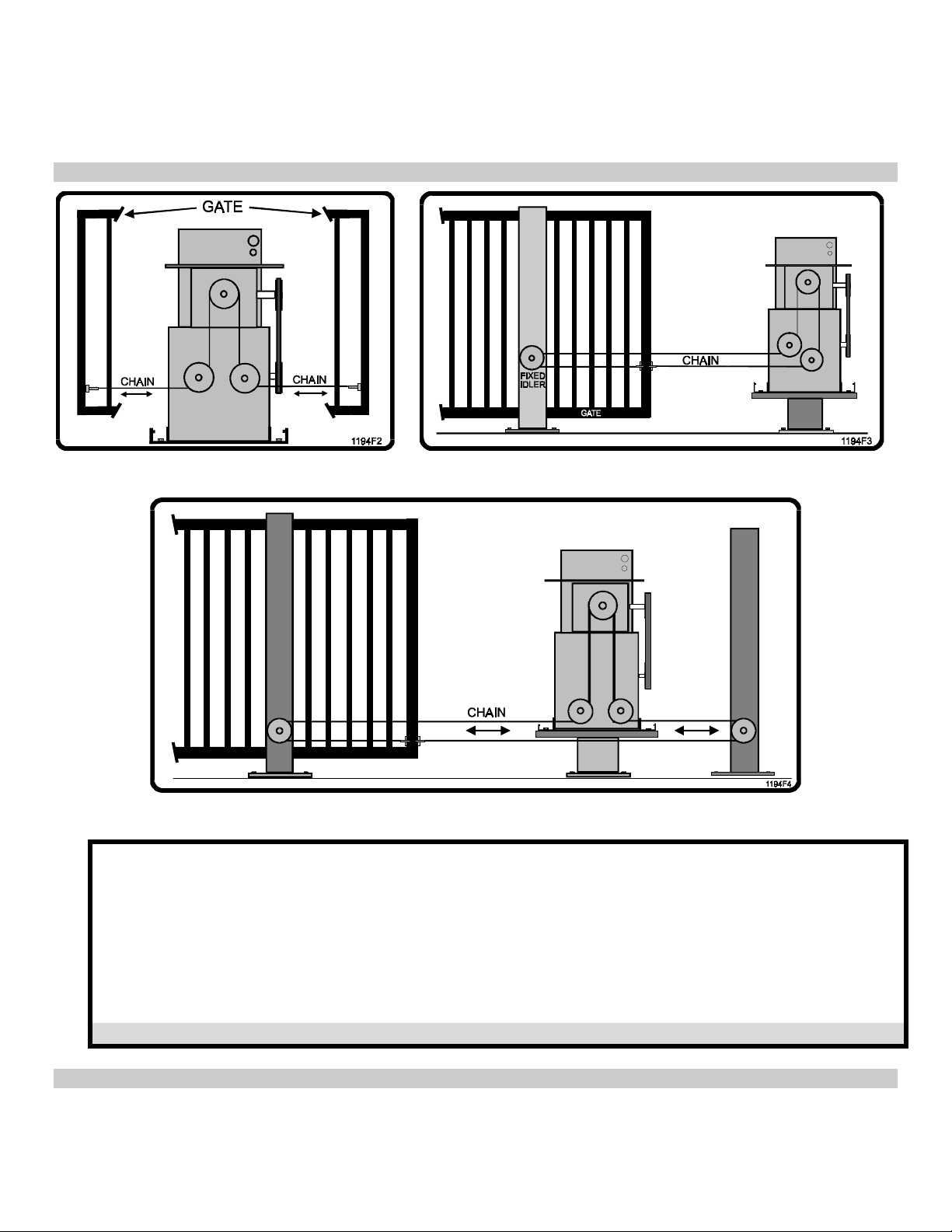
Figure 1. Front Drive. Figure 2. Rear Drive.
Figure 3. Mid Drive.
1. Always install the gate operator on the inside of the fence line, never on the public side of the fence.
2. All manual controls and activating devices should be mounted at least 6 feet away from the gate to
provide safety.
3. Allow enough clearance around the gate and the gate operator for installation and service.
4. The gate operator can provide front and rear drive configuration (Figures 1 and 2), and mid drive
can be used if the operator is post mounted and clearance is provided under the operator for
the chain anchor on the gate (Figure 3).
5. Center idlers may be required on the Mid Drive and Rear Drive configurations to keep the chain
from dragging on itself.
NOTE: Master links and tension adjusters are provided with the gate operator.
Rev C Doc 6001310 (01-20290) 5 of 39
B. PAD AND MOUNT
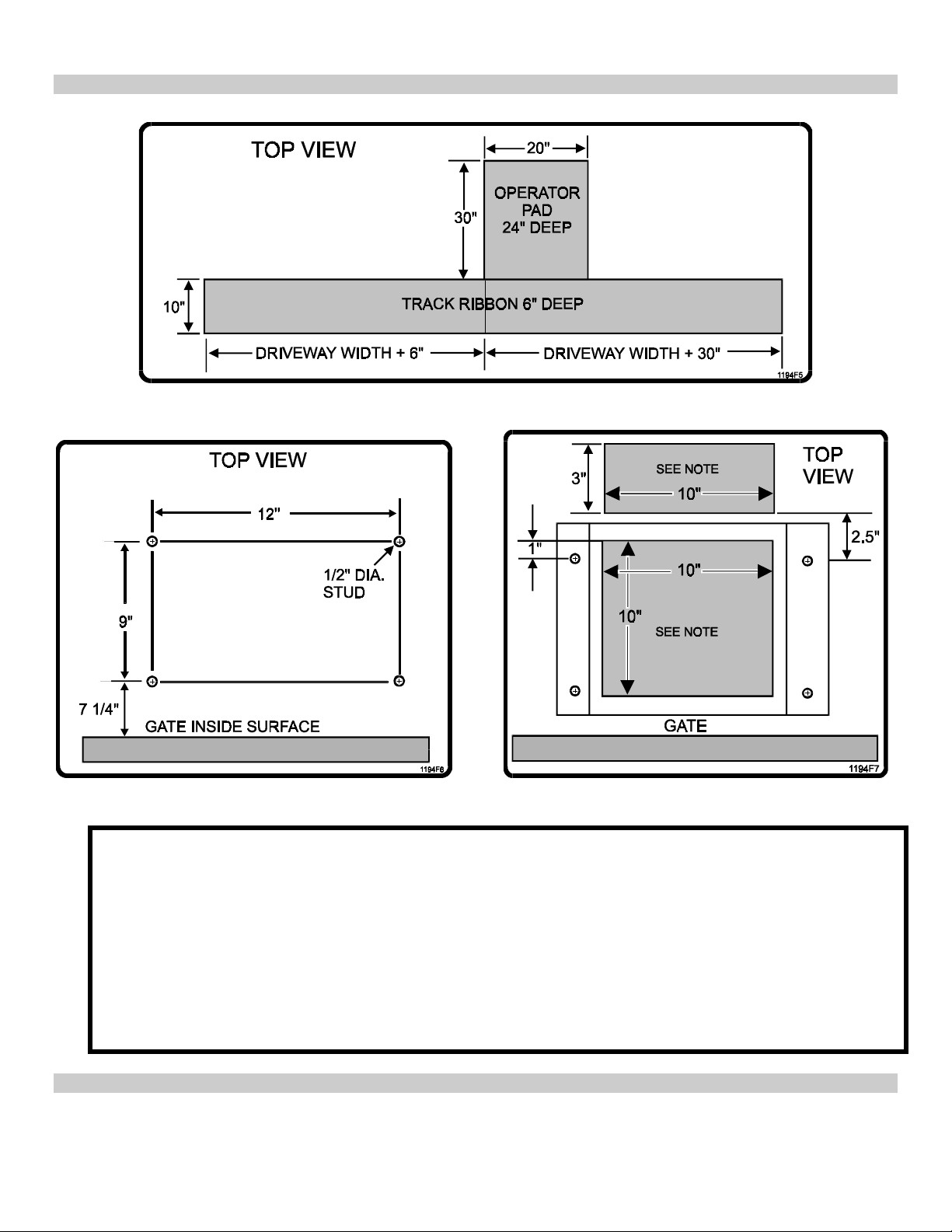
Figure 4. Pad and Track Ribbon.
Figure 5. Bolt Down Pattern. Figure 6. Conduit Entrance Areas.
1. The concrete pad must be sufficient to support the gate operator and the forces created by the
moving gate. LiftMaster recommends a pad 20” wide by 30“ long by 24” deep (Figure 4).
2. The operator must be level and parallel to the gate, so the pad should be level and about 4” above
ground level to prevent water entrance.
3. Four anchor bolts are required to secure the gate operator to the pad. The mounting holes in the
gate operator are 5/8” in diameter. ½” x 3 ½” Red Head bolts are recommended (Figure 5).
4. Be sure to provide access for wiring conduits (Figure 6).
NOTE: Shading indicates acceptable areas for conduit stub access.
5. Track installation should be on concrete, not asphalt, and should be at least 10” wide and 6” deep.
6. A 6” gate overlap at the open end of the gate when closed should be provided.
7. A 30” gate overlap at closed end of the gate when closed should be provided.
Rev C Doc 6001310 (01-20290) 6 of 39

C. POWER WIRING
• Provide a separate conduit stub for the AC power.
• Each gate operator requires a 115 VAC 20 AMP single phase circuit. NOTE: Master and Slave units
each require separate circuits to prevent false overcurrent faults.
• Wiring must comply with the Electrical Code for operating a ½ HP motor (suggest 12 AWG for up to
300’ and 10 AWG for up to 500’ long wire runs).
• Be sure to pull a ground wire in the conduit for the connection to the gate operator.
IMPORTANT: Do not rely on metallic conduit for earth ground.
D. LOOP DETECTORS
• The gate operator has a shelf that can support loop detector electronics. Power for the loop detector
can come from the auxiliary 115 VAC plugs in the gate operator or from the 24 VAC provided by the
gate operator control board.
• Conduit provisions should be made for the “loop” wire entrance to the loop detector.
• The shelf space provided is approximately 4” x 10” x 18” high.
NOTE: Shelf space on systems without the Power Fail Option is about 10” x 10” x 18”
• Wiring should be 16-24 AWG stranded or 18-24 AWG solid.
NOTE: Optional LiftMaster-supplied loop detector add-on boards are available, both pre-installed and
for installation in the field. See Part 3, SL 1000-X1 Options.
E. TELEPHONE CONNECTION
• Provisions should be made for a conduit entrance into the gate operator for the telephone line.
• A single twisted pair wire 18 AWG to 24 AWG, will be connected from the telephone company
termination block through the conduit to J9 on the control board. Polarity is not important.
NOTE: Do not run telephone and AC power wire in the same conduit.
F. MASTER/SLAVE INTERCONNECTION (MASTER/SLAVE SYSTEM ONLY)
• A conduit should be provided for the Master/Slave interconnection cable, run between the Master and
Slave units.
• Two shielded twisted pair wire 16 AWG to 24 AWG will be connected between the two units at TB5 on
the controller board.
NOTES: 1. Do not run the Master/Slave cable and AC power wires in the same conduit.
2. Master/Slave interconnection cable should not exceed 3000 feet in length.
G. OTHER CONNECTIONS
• Provisions should be made for conduit entrance into the gate operator for external activating devices
such as key switches, telephone entry systems, loops, etc.
• Wire size requirement: 16-24 AWG stranded or 18-24 AWG solid wire should be used.
Rev C Doc 6001310 (01-20290) 7 of 39
PART 2
SYSTEM INSTALLATION
A. MOUNTING GATE OPERATOR
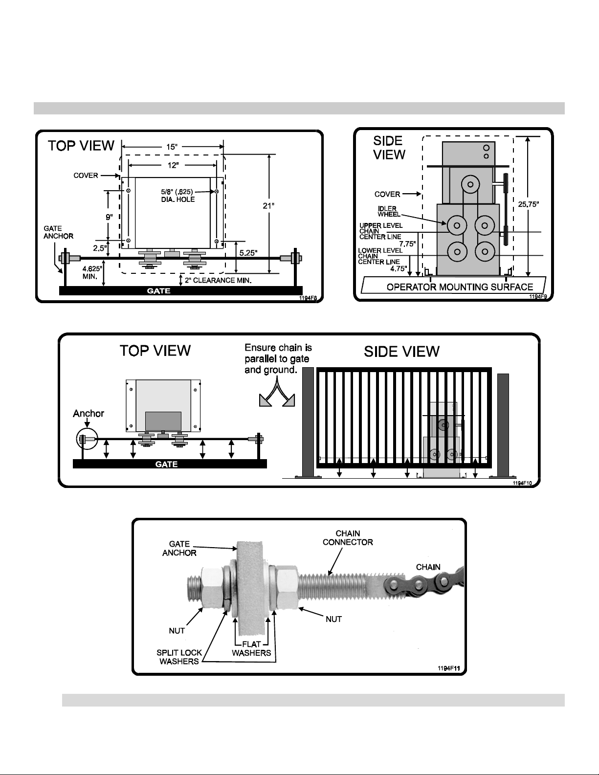
Figure 7. Mounting. Figure 8. Chain Height.
Figure 9. Parallel Chain Location.
Figure 10. Installing Chain on Gate Anchor.
Rev C Doc 6001310 (01-20290) 8 of 39
WARNING
For safety reasons, the Power Fail Operation Option is shipped with the battery unconnected to the
system. Do not connect the battery until all other installation and alignment procedures have
been completed. Failure to observe this warning may result in the Power Fail Operation Option moving
the gate at unexpected moments.
To avoid injury, always turn off the unit power switch before working on gate.
1. Remove the 4 protective bolts that hold the cover on, lift the cover off, and set aside.
2. Remove the assembly kit and parts.
3. Remove the 4 bolts that attach the gate operator to the shipping pallet.
4. Mount gate operator on the cement pad using the previously installed anchor bolts (studs). Be sure
the operator mounting is level and the chain face is parallel to gate movement (Figures 7
and 8).
5. Move the idler wheel mounting if required by this specific installation (Figure 8).
6. Attach gate anchor to gate by welding (Figure 9).
7. Install the chain to the gate using supplied hardware. Adjust nuts for proper chain tension to
prevent the chains from loosening and twisting (Figure 10).
8. Ensure the chain is parallel to gate travel both horizontally and vertically (Figure 9).
9. Connect the power conduit into the switch box.
B. INSTALLING LOCK HASP
The supplied lock hasp may be installed to prevent unauthorized access to the gate operator.
1. Install the lock hasp on the two holes underneath the control box. Orient the hasp with the tongue
at the center of the gate operator chassis and secure in place with supplied hardware.
2. After installing the gate operator cover, a padlock may be used to secure the cover to the lock hasp.
INSTALLATION NOTES
Rev C Doc 6001310 (01-20290) 9 of 39
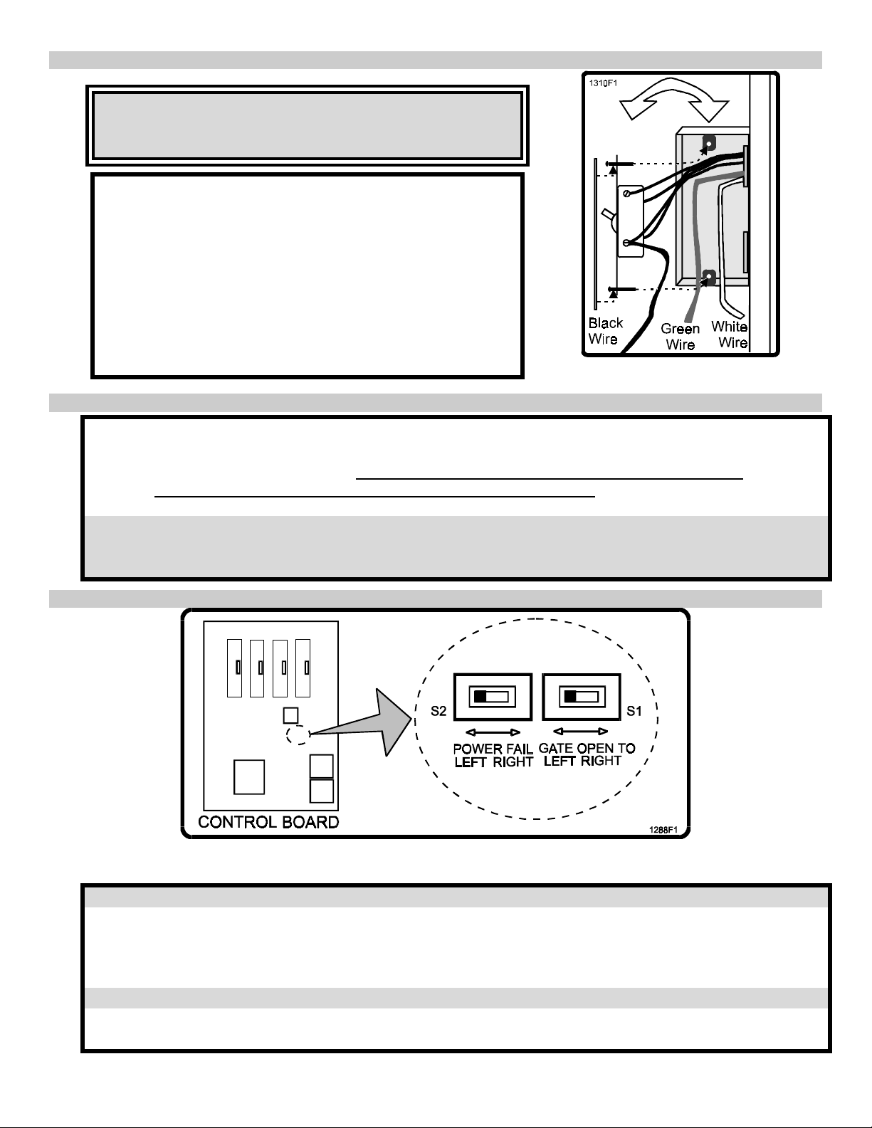
C. CONNECTING POWER
CAUTION
Ensure that the AC power circuit breaker is turned off
before wiring power to the switchbox.
Run power cables through conduit to Gate Operator, then
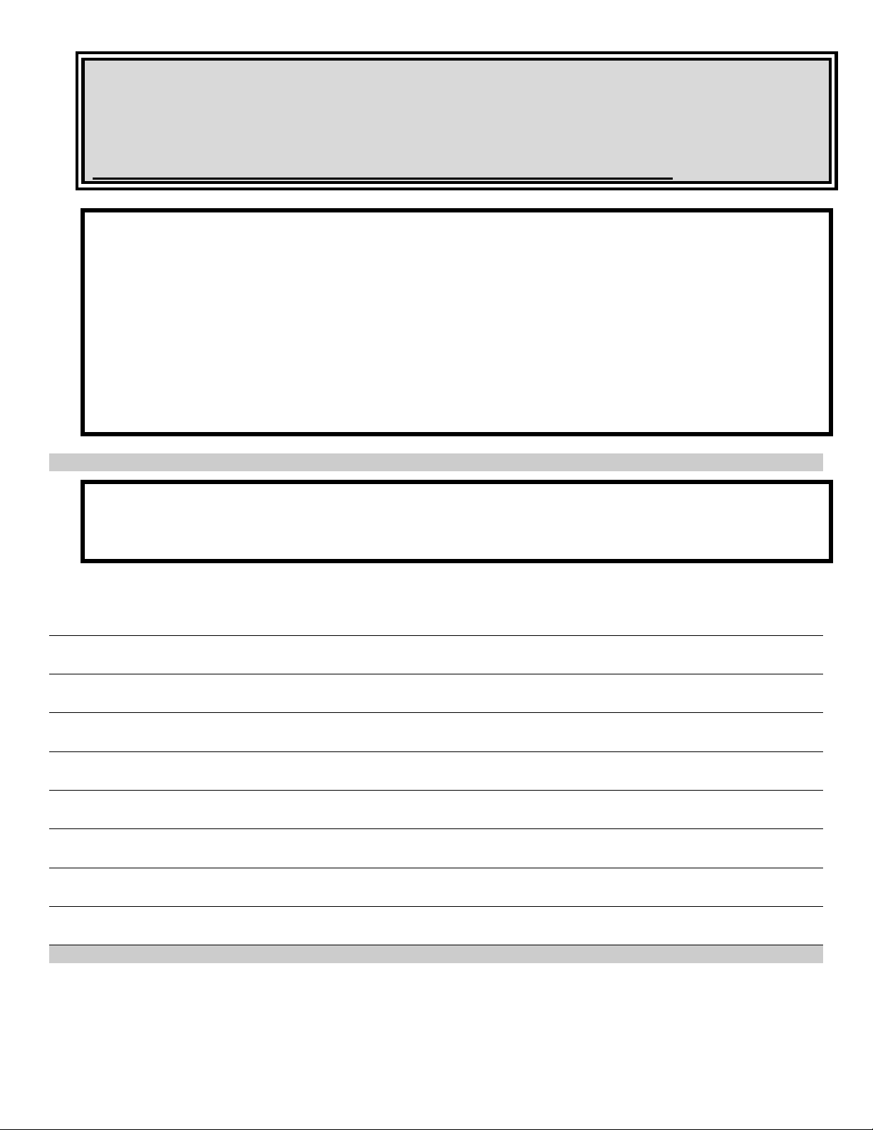
connect wires to the switch box as shown in Figure 11:
1. Wire nut the hot (black) wire to the black pig tail.
2. Wire nut the neutral (white) wire to the white pig
tail.
3. Wire nut the ground (green) wire to the green pig
tail.
4. Dress all wiring inside the switch box and install
cover.
Figure 11. AC Wiring.
D. RUNNING INPUT WIRING
1. Remove the plastic control box cover.
2. Run wires from input components and Master/Slave conduits into control box.
3. For Master/Slave wiring, refer to Installation and Operation Instructions for the LiftMaster
Master/Slave System for X1 Series Gate Operators (-73 Board), Part 2 (Document
Number 6001376).
WARNING
Route but do not connect input wires at this time. If inputs are connected now, the gate operator may
activate at random during installation, potentially injuring installation personnel.
E. SETTING GATE OPEN DIRECTION SWITCHES S1 AND S2
Figure 12. Gate Direction, Power Fail Option Switch Location.
The gate motion left and right is determined by looking at the gate from the gate operator side.
1. Gate opening direction is set by switch S1 on the control board. The switch is sensed only on
power up, so it should be set when the power is off.
2. Ensure power is off.
3. Set the switch to the left or right as required.
If the system was ordered with the Power Fail Operation option:
4. The power failure gate opening direction is set by switch S2, located next to switch S1 on the
control board. Set the switch to the left or to the right as required.
Rev C Doc 6001310 (01-20290) 10 of 39
F. POWER UP PROCEDURE
CAUTION
If gate is positioned at the ‘open’ limit, gate will automatically close when
power is switched on. Position gate either at the closed limit or at no limit
when preparing to switch power on. Always use extreme caution and
follow all warnings in the Safety Summary.
1. Turn on circuit breaker that provides power to gate operator.
2. Turn on gate operator power switch and verify that the seven-segment LED display above the
keypad sequentially spells out “HELLO”.
NOTE: If the display does not follow this pattern, the controller board may not be working correctly.
Stop installation and call LiftMaster Technical Support for assistance.
♦ The only LEDs that should remain on are MAGLOCK and CLOSE LIMIT or OPEN LIMIT, if one of
the limit switches are engage.
♦ If gate is positioned at the open limit, it will automatically cycle to the full closed position. If gate is
positioned anywhere else, it will not move until commanded.
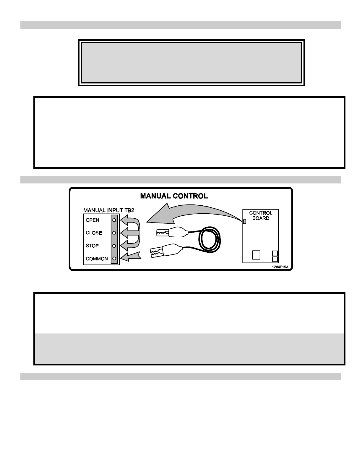
G. USING MANUAL CONTROLS
Figure 13. Manual Controls, Location and Operation.
If necessary, use the manual controls on Manual Input Terminal TB2 (OPEN, CLOSE, and STOP, as
shown in Figure 5), to move the gate arm during system installation.
• To open the gate: connect the OPEN and STOP terminals to the COMMON terminal.
• To close the gate: connect the CLOSE and STOP terminals to the COMMON terminal.
• To stop the gate: disconnect the STOP terminal from the COMMON terminal.
IMPORTANT NOTE
If the STOP terminal is disconnected from the Common terminal, the gate is prevented
from moving and no command will affect the gate.
Rev C Doc 6001310 (01-20290) 11 of 39
 Loading...