

Page 1
OWNER'S MANUAL
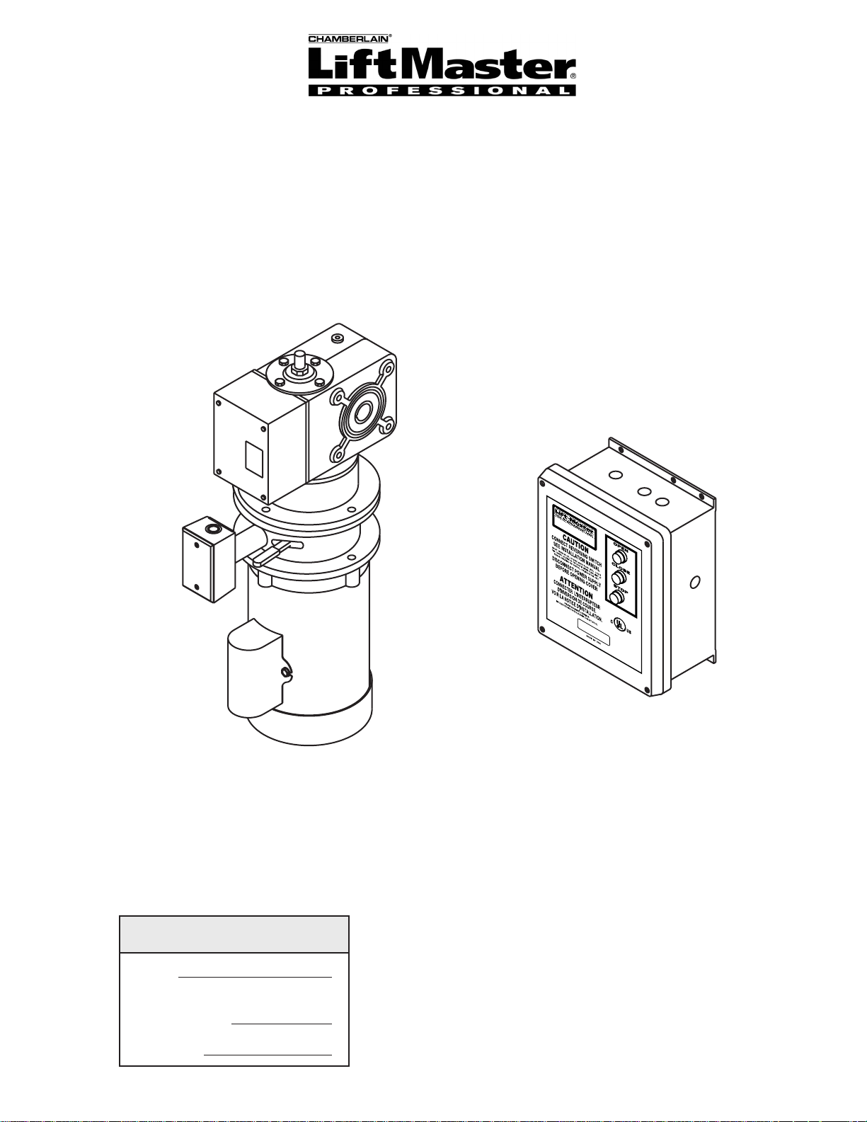
MODEL SJ
SPEED JACKSHAFT OPERATOR
THE
CHA
ELM
M
BER
HUR
LAIN G
ST, ILLIN
RO
OIS 60126
UP, IN
C.
2 YEAR WARRANTY
Serial #
(located on electrical box cover)
Installation Date
41
B6
LIS
PLACE RATING L
TED DOO
R
O
ABEL HERE
PERAT
OR
NOT FOR RESIDENTIAL USE
Wiring Type
Page 2

SPECIFICATIONS
MOTOR
TYPE:....................................AC Synchronous
continuous duty
ENCLOSURE:.......................ODP NEMA 56c face
mount.
HORSEPOWER:...................1 HP
Single or Three phase
SPEED:.................................1725 RPM
VOLTAGE:.............................115 & 230 Single phase
230 & 460 Three phase
575 Three phase
CURRENT:..................................See motor nameplate
DRIVE SYSTEM
CONTINUOUS
POWER RATING: .................260 Ft-Lbs/Sec
GEAR BOX:..........................Worm gear
LUBRICATION:.....................Oil Bath
RATIO: ..................................45:1
OUTPUT SPEED: .................38 rpm
DOOR SPEED:.........................10 - 17" per sec.
depending on door
ELECTRICAL
TRANSFORMER:...............1PH: 120/240 VAC 24VAC
3PH: 240/480 VAC 24VAC
3PH: 575 VAC 24VAC
CONTROL STATION: ........NEMA 4 three button station.
OPEN/CLOSE/STOP
WIRING TYPE: ...................Standard C2 Wiring- Standard
operators are shipped from the factory set for C2 wiring,
which requires momentary contact to open, constant
pressure to close, stop on reverse.
B2 Wiring Option- Dip switch selectable, momentary contact
to open, close and stop. Entrapment protection device must
be included.
Wiring for sensing device to reverse and auxiliary devices to
open and close with open override.
LIMIT ADJUST: ..................Rotary driven, fully
adjustable screw type cams. Adjustable to 30 feet.
ACCESSORY POWER
AVAILABLE:.......................115V & 230V Single Phase -
25VA
230V & 460V Three Phase -
25VA
575V Three Phase - 40VA
DUTY CYCLE: ......................25 Reversing cycles per hour
BRAKE:.................................24VDC electromagnetic disc
EGJ DIMENSIONS
12.36”
4.73”
8.38”
2.76”
SAFETY
SAFETY EYES: ..............Liftmaster CPS-LN4
REVERSING EDGE:.......(Optional) Electric or pneumatic
sensing device attached to the bottom edge of door.
A REVERSING EDGE IS STRONGLY RECOMMENDED
ALL
FOR
REQUIRED
IS OUT OF SIGHT OF DOOR OR ANY OTHER
CONTROL (AUTOMATIC OR MANUAL) IS USED.
3.94”
COMMERCIAL OPERATOR INSTALLATIONS.
WHEN THE 3 BUTTON CONTROL STATION
See Chart
9.13”
1/2” HEX
1” DIA. WITH
1/4” KEYWAY
PHASE
HP
1
1
1
3
DIMENSION
22-3/8”
21-1/8”
2
Page 3

WARNING
CAUTION
WARNING
WARNING
WARNING
IMPORTANT SAFETY NOTES
CAUTION
TO AVOID DAMAGE TO DOOR AND OPERATOR,
MAKE ALL DOOR LOCKS INOPERATIVE. SECURE
LOCK(S) IN "OPEN" POSITION.
IF THE DOOR LOCK NEEDS TO REMAIN
FUNCTIONAL, INSTALL AN INTERLOCK SWITCH.
DO NOT CONNECT ELECTRIC POWER UNTIL
INSTRUCTED TO DO SO.
KEEP DOOR BALANCED. STICKING OR BINDING
DOORS MUST BE REPAIRED. DOORS, DOOR
SPRINGS, CABLES, PULLEYS, BRACKETS AND
THEIR HARDWARE MAY BE UNDER EXTREME
TENSION AND CAN CAUSE SERIOUS PERSONAL
INJURY. CALL A PROFESSIONAL DOOR
SERVICEMAN TO MOVE OR ADJUST DOOR
SPRINGS OR HARDWARE.
WARNING
SITE PREPARATIONS
It is imperative that the wall or mounting surface provide adequate support for the operator. The safety and wear
of the operator will be adversely affected if any of the following requirements are not met.
a) Mounting surface to be rigid to prevent play between operator and door shaft.
b) Provide a level base.
c) Permit the operator to be fastened securely and with the drive shaft parallel to the door shaft.
INSTALLATION INSTRUCTIONS
TYPICAL SHAFT INSTALLATION
1. Slide the shaft collar supplied over the door shaft to
desired position and secure in place.
2. Slide the operator on the door shaft until it contacts the
shaft collar. Insert the 4-1/2” key supplied into the operator
and the door shaft.
3. Slide the second shaft collar on the door shaft until it
contacts the operator and secure in place, this will hold the
4-1/2” key in place.
4. Mount torque arm using 5/16-18 x 1” hex bolt to gear
box as shown in figures 1 & 2.
NOTE: For additional help refer to the illustrations below.
Shaft
Collar
Hex Bolt
Shaft Collar
Hex Bolt
Door
Shaft
4-1/2” Key
T or que Arm
FIGURE 1
Right hand unit shown, hex bolts and
torque arms supplied by others, Door
side plates removed for clarity.
Part of Door
FIGURE 2
Right hand unit shown installed, Door
side plates removed for clarity.
Page 4
ENTRAPMENT PROTECTION ACCESSORIES (OPTIONAL)
SAFETY EYES:
Compatible with Liftmaster CPS-LN4 direct connect failsafe
photoeyes.
SENSING EDGES
All types of sensing edges with an isolated normally open
(N.O.) output are compatible with your operator. This
includes pneumatic and electric edges. If your door does
not have a bottom sensing edge and you wish to purchase
one, contact the supplier of your operator.
If not pre-installed by the door manufacturer, mount the
sensing edge on the door according to the instructions
provided with the edge. The sensing edge may be
electrically connected by either coiled cord or take-up reel.
Refer to the steps below.
Important Notes:
a) Proceed with Limit Switch Adjustments before making
any sensing edge wiring connections to operator as
described below.
b) Electrician must hardwire the junction box to the
operator electrical box in accordance with local codes.
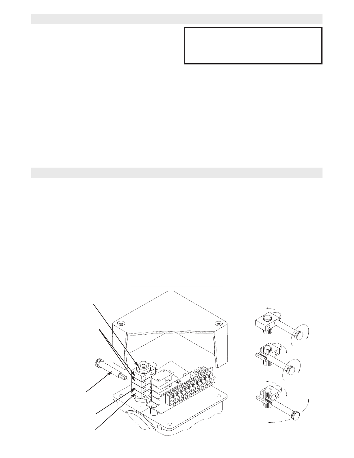
LIMIT SWITCH ADJUSTMENT
THE LIMIT SWITCHES WILL STOP THE DOOR AT EACH
END OF TRAVEL. ADDITIONAL LIMIT SWITCHES CAN
BE USED FOR CONTROL OF OTHER AUTOMATIC
FUNCTIONS.
NOTE: Before starting adjustment of the limit switches,
loosen or tighten (if necessary) the lock nut in order to
obtain a convenient adjustment tightness of the cam
wheels. After finishing the adjustments, make sure that the
lock nut is sufficiently tight 1 NM (8”LBS) to retain the cam
wheels securely during operation.
When door is in the fully open position, the green cam
wheel (Open) will be turned into contact with its
corresponding switch. In the same way, just before the
door is in the closed position, the black cam wheel (Closed)
will activate its switch.
IT IS STRONGLY RECOMMENDED THAT A
SENSING EDGE OR OTHER ENTRAPMENT
PROTECTION DEVICE BE USED IN
CONJUNCTION WITH THIS OPERATOR.
WIRING:
For wiring of your sensing device to the operator,
refer to the wiring diagram supplied with your
operator. See field connection terminals identified as
Sensing Device or Safety Edge.
TAKE-UP REEL: Take-up reel should be installed
12" above the top of the door.
COIL CORD: Connect operator end of coil cord to
junction box (not supplied) fastened to the wall
approximately halfway up the door opening.
COARSE ADJUSTMENT
The coarse adjustment of the limit switches can be done by
inserting a rod or a screw driver into one of the adjustment
holes in the cam wheels and by turning each cam wheel
with the rod or screw driver.
FINE ADJUSTMENT
Fine adjustment can be done by screwing the adjustment
screw (supplied) against the cam shaft thread inside each
cam wheel. The screw must be changed from one
adjustment hole into the other for turning the cam wheel in
the opposite direction.
Lock Nut
Auxiliary Limit Switches
(When Supplied)
Adjustment Screw
Close Limit (Black)
Open Limit (Green)
LIMIT BOX ON POWERHEAD
FINE
ADJUSTMENT
CCW
CW
COARSE
ADJUSTMENT
4
Page 5

WARNING
POWER WIRING CONNECTIONS
Remove the cover from the wall mounted starter. Inside this enclosure you will find the wiring diagram(s)
for your unit. Refer to the wiring diagrams for all connections described below. If this diagram is missing,
call the number on the back of this manual. DO NOT INSTALL ANY WIRING OR ATTEMPT TO RUN THIS
OPERATOR WITHOUT CONSULTING THE WIRING DIAGRAM.
POWER WIRING
1. Be sure that the power supply is of the correct
voltage, phase, frequency, and amperage to supply the
operator. Refer to the operator nameplate on the
cover.
2. Drill recommended 7/8” dia. holes at approximate
locations shown below, and bring supply lines to the
wall mounted starter and connect wires to the
terminals indicated on the WIRING CONNECTIONS
DIAGRAM.
IN ORDER TO KEEP NEMA-4 INTEGRITY,
“LIQUIDTITE” CONDUIT CONNECTIONS MUST BE
USED.
DISCONNECT POWER AT THE FUSE BOX BEFORE
PROCEEDING.
OPERATOR MUST BE PROPERLY GROUNDED AND
CONNECTED IN ACCORDANCE WITH LOCAL
ELECTRICAL CODES. NOTE: THE OPERATOR
SHOULD BE ON A SEPARATE FUSED LINE OF
ADEQUATE CAPACITY.
ALL ELECTRICAL CONNECTIONS MUST BE MADE
BY A QUALIFIED INDIVIDUAL.
WARNING
WARNING
DO NOT TURN POWER ON UNTIL YOU HAVE
FINISHED MAKING ALL POWER AND CONTROL
WIRING CONNECTIONS AND HAVE COMPLETED
THE LIMIT SWITCH ADJUSTMENT PROCEDURE.
IMPORTANT: THIS UNIT MUST BE PROPERLY
GROUNDED. A GROUND SCREW IS SUPPLIED IN
THE ELECTRICAL BOX FOR CONNECTION OF
THE POWER SUPPLY GROUND WIRE. FAILURE TO
PROPERLY GROUND THIS UNIT COULD RESULT
IN ELECTRIC SHOCK AND SERIOUS INJURY.
Recommended 7/8” Dia hole for
limit conduit access
THE CHAMBERLAIN GROUP, INC.
ELMHURST, ILLINOIS 60126
41B
6
LIS
P
TED
L
A
C
E
D
R
A
O
T
IN
O
G
R
L
O
A
B
E
P
L
E
H
R
E
R
ATO
E
R
TO AVOID DAMAGE TO DOOR AND OPERATOR,
MAKE ALL DOOR LOCKS INOPERATIVE. SECURE
LOCK(S) IN "OPEN" POSITION.
IF THE DOOR LOCK NEEDS TO REMAIN
FUNCTIONAL, INSTALL AN INTERLOCK SWITCH.
Recommended 7/8” Dia hole for
brake/electrical disconnect conduit access
Recommended 7/8” Dia hole for
motor conduit access
Recommended 7/8” Dia hole for
power conduit access
Recommended 7/8” Dia hole for
photo eyes conduit access
WARNING
Do Not Run Power &
Control Wiring in the
Same Conduit
Recommended 7/8” Dia hole for
safety edge conduit access
5
Page 6
CONTROL WIRING
WARNING
DETERMINE WIRING TYPE
Refer to the wiring diagram located on the inside cover the electrical box to determine the type of control wiring.
SPECIAL CONTROL WIRINGWIRING TYPES
Standard C2 Wiring
Standard operators are shipped from the factory set
for C2 wiring, which requires momentary contact to
open, constant pressure to close, stop on reverse.
If your operator was shipped from the factory with
non-standard control wiring or with optional
accessories that require additional instructions, refer
to the wiring diagram(s) indicated in the special
control wiring data box. When a replacement wiring
B2 Wiring Option
Dip switch selectable, momentary contact to open,
close and stop. Entrapment protection device must
diagram is present, wiring diagrams in this manual
will not apply. Refer only to the replacement wiring
diagram for all connections.
be included.
IMPORTANT NOTE: If your wiring diagram is
missing, or you are unsure of the wiring type for
your operator, contact the customer service
department @ 1-800-528-2806.
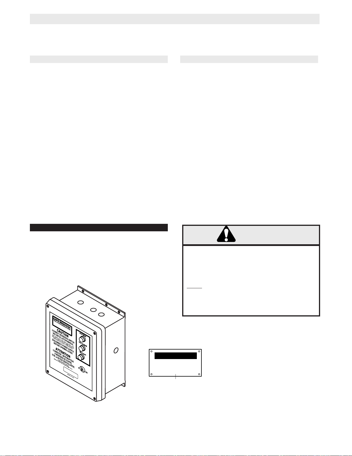
LOCATING THE CONTROL STATION
All operators are supplied with a three button station (OPEN/CLOSE/STOP) incorporated into the wall mounted
starter. Mount the wall mounted starter where the door is visible, but not directly underneath the door, operator, or
mounting hardware.
MOUNT WARNING NOTICE
IMPORTANT: Mount WARNING NOTICE beside or
below the wall mounted starter.
WARNING
THE CHAM
ELMHURST, ILLINO
BERLAIN GROUP, INC
INSTALL THE WALL MOUNTED STARTER WHERE
THE DOOR IS VISIBLE, BUT AWAY FROM THE DOOR
AND ITS HARDWARE. IF STARTER CANNOT BE
INSTALLED WHERE DOOR IS VISIBLE, OR IF ANY
DEVICE OTHER THAN THE CONTROL STATION IS
USED TO A CTIVATE THE DOOR,
MUST
DOOR.
BE INSTALLED ON THE BOTTOM OF THE
FAILURE TO INSTALL A REVERSING EDGE
A REVERSING EDGE
UNDER THESE CIRCUMSTANCES MAY RESULT IN
SERIOUS INJURY OR DEATH TO PERSONS
TRAPPED BENEATH THE DOOR.
IS 60126
.
WARNING
4
1
B
6
L
IS
P
T
L
E
A
C
D
E
D
R
A
O
TING
O
R
L
O
A
BE
P
L
E
H
R
E
R
A
E
T
O
R
TO PREVENT ENTRAPMENT
DO NOT START DOOR DOWNWARD
UNLESS DOORWAY IS CLEAR
WARNING Notice
6
Page 7

CONTROL WIRING (con’t)
WARNING
WARNING
Radio Controls
All radio controls must have dry contact relay
outputs. Power for radio is to be supplied by an
outside source. Do not take power from the
components inside the electrical enclosure.
Additional Access Control Equipment
Locate any additional access control equipment as desired (but so that the door will be in clear sight of the person
operating the equipment), and connect to the terminal block in the electrical enclosure as shown on the FIELD
WIRING CONNECTIONS diagram. Any control with a normally (N.O.) isolated output contact may be connected
in parallel with the OPEN button. More than one device may be connected in this manner. Use 16 gauge wire or
larger for all controls. DO NOT USE THE CONTROL CIRCUIT TRANSFORMER (24VAC) IN THE OPERATOR
TO POWER ANY ACCESS CONTROL EQUIPMENT OTHER THAN A STANDARD RESIDENTIAL TYPE RADIO
RECEIVER.
DO NOT USE RADIO CONTROLS WITH YOUR
OPERATOR UNLESS YOU HAVE INSTALLED
SOME TYPE OF ENTRAPMENT PROTECTION
DEVICE. THE USE OF RADIO CONTROLS
PRESENTS POTENTIAL HAZARDS DUE TO THE
USER’S ABILITY TO OPEN OR CLOSE THE
DOOR WHEN OUT OF SIGHT OF THE DOOR.
WARNING
Manual Release Brake
The operator is equipped with a internal interlock switch mounted to the brake assembly. When the brake is
manually dis-engaged the control circuit will be disabled, thereby preventing electrical operation of the door from
the control devices.
The operator has been pre-wired to accept
WARNING
IF CONTROL STATION CANNOT BE INSTALLED WHERE
DOOR IS VISIBLE, OR IF ANY DEVICE OTHER THAN
THE CONTROL STATION IS USED TO ACTIVATE THE
DOOR,
THE BOTTOM OF THE DOOR.
REVERSING EDGE UNDER THESE CIRCUMSTANCES
MAY RESULT IN SERIOUS PERSONAL INJURY OR
DEA TH TO PERSONS TRAPPED BENEATH THE DOOR.
A REVERSING EDGE MUST BE INSTALLED ON
FAILURE TO INSTALL A
NOTICE:
This equipment has been tested and found to comply with the limits for a Class A digital
device, pursuant to Part 15 of the FCC Rules. These limits are designed to provide
reasonable protection against harmful interference when the equipment is operated in a
commercial environment. This equipment generates, uses, and can radiate radio frequency
energy and, if not installed and used in accordance with the instruction manual, may cause
harmful interference to radio communications. Operation of this equipment in a residential
area is likely to cause harmful interference, in which case the user will be required to correct
the interference at his own expense.
connection of a reversing edge device. Connect the
normally open contacts to terminals 5 and 6 located
on the LMPLC board. An auxiliary limit switch (yellow)
will deactivate the safety device during the last few
inches of the door’s downward travel.
7
Page 8

CONTROL WIRING (con’t)
Auxiliary Contacts
Three auxiliary normally open dry contacts will be
available. They will accept a max. of 15 amps, 120V
AC/DC. Terminal Block J2 located on the LMPLC
board is used to access these contacts.
1) Terminal J2-17 and J2-18 will close when the door
is fully closed.
POWER WIRING
POWER WIRING CONNECTIONS
1. Connect power wires to the J1 terminal block
located on the Printed Circuit Board (shown below).
(See wiring diagram page 11, 13, and 15)
2) Terminal J2-19 and J2-20 will close when the door
is stopped at any position other than fully closed.
3) Terminal J2-21 and J2-22 will close when the door
is in motion.
Single button control is available as an optional
device and is wired to terminals J2-11 and J2-12 on
the LMPLC board.
CONTROL STATION WIRING
CONTROL WIRING CONNECTIONS
1. Connect control wires to the J2 terminal block
located on the Printed Circuit Board (shown below).
(See wiring diagram page 11, 13 and 15)
GROUND WIRING
1. Connect earth ground to chassis ground screw in the
electrical box enclosure marked with the label shown
below.
40-10033B
2. Use same conduit entry into the electrical box as the
power wiring.
(See wiring diagram page 11, 13 and 15)
2. Apply power to the operator. Press OPEN push
button and observe direction of door travel and then
Press the STOP button.
If door did not move in the correct direction, check for
improper wiring at the control station or between
operator and control station.(See page 19)
8
Page 9

OPTIONAL CONTROL SETTINGS
NOTE: All functions are independent of each other and do not require other control settings to be set at any
certain configuration. For dip switch location refer to illustration below. All switches are factory preset to the “OFF”
position.
SI-1 WIRING TYPE - B2 wiring in the OFF position and C2 wiring in the ON position.
SI-2 NOT USED
SI-3 NOT USED
SI-4 INFRARED EYES STATE - The operator will support Chamberlain (CPS LN4) Infrared Eyes when
enabled, and ignore IR inputs when disabled.
TERMINAL
BLOCK (J1)
ON (C2)
1 2 3 4
OFF (B2)
DIP SWITCH (S1)
TERMINAL
BLOCK (J2)
ON (IR'S ENABLED)
1 2 3 4
OFF (IR'S DISABLED)
NOTICE:
This equipment has been tested and found to
comply with the limits for a Class A digital
device, pursuant to Part 15 of the FCC Rules.
These limits are designed to provide
reasonable protection against harmful
interference when the equipment is operated
in a commercial environment. This equipment
generates, uses, and can radiate radio
frequency energy and, if not installed and used
in accordance with the instruction manual,
may cause harmful interference to radio
communications. Operation of this equipment
in a residential area is likely to cause harmful
interference, in which case the user will be
required to correct the interference at his own
expense.
HEAT SINK
9
Page 10

TEST THE SYSTEM
WARNING
Turn on power. Test all controls and safety devices to
make sure they are working properly. It will be
necessary to refer back to page 4 for fine adjustment
of the limit switches.
IMPORTANT NOTES:
Do not leave operator power on unless all safety
and entrapment protection devices have been
tested and are working properly.
Be sure you have read and understand all Safety
Instructions included in this manual.
Be sure the owner or person(s) responsible for
operation of the door have read and understand
the Safety Instructions, know how to electrically
operate the door in a safe manner, and know how
to use the manual disconnect operation of the
door operating system.
WARNING
DO NOT PLACE HANDS OR TOOLS IN OR NEAR
THE OPERATOR WHEN THE POWER IS ON OR
WHEN TESTING CONTROL OR SAFETY
DEVICES. ALWAYS DISCONNECT POWER
BEFORE SERVICING OR ADJUSTING THE
OPERATOR.
10
Page 11

115V - 208/230V 1 PHASE SCHEMATIC DIAGRAM
02264-1
T1
T2
T3
T4
115 VOLT - 1 PHASE
MOTOR CONNECTION
OUTPUTS
CLOSED WHEN DOOR IS IN
MOTION
CLOSED WHEN THE DOOR IS
STOPPED AT ANY POSITION
OTHER THAN FULLY CLOSED
CLOSED WHEN THE DOOR IS
FULLY CLOSED
ACCESSORY POWER 25VA
INTERNAL TIMER
DEFEAT SWITCH
(RD)
EXTERNAL
TIMER
(RD)
GY
BL
YE
PU
3
1
8
5
4
2
J14
J13
T2- NOT USED
J15
(RD)
R1
J12
J9
J8
14 15 16 17 18 19 20 21 22 23 24
13
12345 67 8 9101112
GY
T1
YE
T3
PU
T4
1
2
8
BL
5
4
208/230 VOLT - 1 PHASE
MOTOR CONNECTION
AX
CL
OP
(BL)(RD)(YE)
J3
(WH)
(RD)
(BL)
(BR)
(OR)
7
4
1
(BL)
J30
J4
ZILOG PROCESSOR
3
B1
S1
J2
AUXILARY CLOSE
LIMIT SWITCH
(YELLOW)
CLOSE LIMIT
SWITCH
(BLACK)
OPEN LIMIT
SWITCH
(GREEN)
(WH)
DC BRAKE
(WH)
WIRE NUTWIRE NUT
B2
(BL/BK)(BL/BK)
J17
J16
J19
J18
NOTES:
1) TO REVERSE MOTOR DIRECTION: REVERSE
PURPLE AND GREY MOTOR WIRES (T1 AND T4).
2) USE 16 GAUGE OR HEAVIER WIRE, FOR ALL
CONTROL CIRCUIT WIRING.
3) SEE OWNERS MANUAL FOR DIP SWITCH
FUNCTIONS AND PROGRAMMING PROCEDURES.
8
5
2
J27
INTERNAL
INTERLOCK
J21
J22
J26
(BK)
(BK)
J5
(YE)
(BL)
(RD)
J1
L1 L2 L3
WIRE NUT
CM
ED2
(YE)
J24
J23
J6
J7
(OR)
J25
J28
J20
J29
(GY)
(PU)
(BL)
ED1
(RD)
CHASSIS
GROUND
T3
T1
T4
T2
CPS LN4
PHOTO EYES
(BR)
R1
REVERSE
EDGE
(BR)
11
OPEN
CLOSE
STOP
(YE)
(PU)
(RD)
(OR)
24V
TRANSFORMER
BRAKE
AND
BOARD
SECONDARY
(BK)
1PH.
(BK)
POWER IN
OVERLOAD
SINGLE BUTTON CONTROL
RADIO 412HM
COM
PRIMARY LINE VOLTAGE
PRIMARY
(WH)
CHASSIS
GROUND
(BK)
Page 12

115V - 208/230V 1 PHASE FIELD CONNECTION DIAGRAM
WALL MOUNTED
STARTER
CPS LN4
PHOTO EYES
SAFTEY EDGE
SINGLE BUTTON CONTROL
RADIO 412HM
DOOR IS FULLY OPEN
WHEN THE DOOR IS
STOPPED AT ANY POSITION
OTHER THAN FULLY OPEN
DOOR IS IN MOTION
POWERHEAD
LIMIT BOX
1
2
3
4
THESE TERMINALS ARE
5
LOCATED ON THE LMPLC
BOARD
6
7
8
9
10
11
12
17
*
18
19
*
20
21
*
22
DRY CONTACTS ONLY. NORMALLY
*
OPEN 15 AMPS 120V AC/DC MAX.
1PH
POWER IN
GROUND
GROUND
L1
L2
L3
T1
T2
T3
T4
T1
T3
T4
ED2
ED1
B1
B2
OP
CM
CL
AX
WIRE NUTS
115V 1 PHASE
MOTOR
208/230V 1PH
MOTOR
(WH)
(WH)
1
4
7
DC BRAKE
(GREEN)
(BLACK)
(YELLOW)
INTERNAL
INTERLOCK
2
5
8
OPEN LIMIT SWITCH
CLOSE LIMIT SWITCH
AUXILIARY CLOSE
LIMIT SWITCH
12
Page 13

208/230V - 460V 3 PHASE SCHEMATIC DIAGRAM
02264-3
T1
T2
T3
OUTPUTS
CLOSED WHEN DOOR IS IN
MOTION
CLOSED WHEN THE DOOR IS
STOPPED AT ANY POSITION
OTHER THAN FULLY CLOSED
CLOSED WHEN THE DOOR IS
FULLY CLOSED
ACCESSORY POWER 25VA
INTERNAL TIMER
DEFEAT SWITCH
(RD)
GY
PUR
YEL
1
2
3
7
4
85
9
6
208/230 VOLT - 3 PHASE
MOTOR CONNECTION
J14
(RD)
J8
GY
T1
PUR
T2
YEL
T3
1
2
3
7
4
85
9
6
460 VOLT - 3 PHASE
MOTOR CONNECTION
AUXILARY CLOSE
LIMIT SWITCH
AX
CL
J3 J4
J15
J13
J12
J9
13 14 15 16 17 18 19 20 21 22 23 24
(WH)
(RD)
(BL)
(BR)
OP
(BL)(BL)(RD)(YE)
ZILOG PROCESSOR
7
4
1
(YELLOW)
CLOSE LIMIT
SWITCH
(BLACK)
OPEN LIMIT
SWITCH
(GREEN)
(WH)
(WH)
WIRE NUTWIRE NUT
B1
B2
(BL/BK)(BL/BK)
J17
J30
J19
J18
S1
J2
DC BRAKE
J16
INTERNAL
INTERLOCK
J21
NOTES:
1) TO REVERSE MOTOR DIRECTION: REVERSE
PURPLE AND GREY MOTOR WIRES (T1 AND T2).
2) USE 16 GAUGE OR HEAVIER WIRE, FOR ALL
CONTROL CIRCUIT WIRING.
3) SEE OWNERS MANUAL FOR DIP SWITCH
FUNCTIONS AND PROGRAMMING PROCEDURES.
8
5
2
WIRE NUT
(BK)
(BK)
CM
J5
J23
(RD)
J20
ED1
ED2
(YE)
J24
(PU)
J6
(GY)
J7
(BK)
J25
(BK)
J28
(RD)
CHASSIS
GROUND
T3
T2
T1
EXTERNAL
TIMER
(RD)
R1
12345 67 8 9101112
(OR)
OPEN
CPS LN4
PHOTO EYES
R1
REVERSE
EDGE
(OR)
CLOSE
STOP
(YE)
(PU)
(RD)
J22
J26
J27
(BL)
SINGLE BUTTON CONTROL
RADIO 412HM
J1
L1 L2 L3
3PH
POWER IN
(BK)
J29
(BK)
(BR)
(BR)
(BK)
(BK)
T3
L3
T2
L2
L1
T1
95
96
TRANSFORMER
(WH)
(BK)
(BR)
24V
SECONDARY
BRAKE
AND
BOARD
COM
PRIMARY LINE VOLTAGE
PRIMARY
13
Page 14

208/230V - 460V 3 PHASE FIELD CONNECTION DIAGRAM
WALL MOUNTED
STARTER
CPS LN4
PHOTO EYES
SAFTEY EDGE
SINGLE BUTTON CONTROL
RADIO 412HM
DOOR IS FULLY OPEN
WHEN THE DOOR IS
STOPPED AT ANY POSITION
OTHER THAN FULLY OPEN
DOOR IS IN MOTION
POWERHEAD
LIMIT BOX
1
2
3
4
5
6
7
8
9
10
11
12
17
*
18
19
*
20
21
*
22
THESE TERMINALS ARE
LOCATED ON THE LMPLC
BOARD
DRY CONTACTS ONLY. NORMALLY
*
OPEN 15 AMPS 120V AC/DC MAX.
3PH
POWER IN
GROUND
L1
L2
L3
T1
T2
T3
ED2
ED1
B1
B2
OP
CM
CL
AX
WIRE NUTS
208/230V - 460V
3 PHASE MOTOR
(WH)
(WH)
1
4
7
DC BRAKE
(GREEN)
(BLACK)
(YELLOW)
INTERNAL
INTERLOCK
2
5
8
OPEN LIMIT SWITCH
CLOSE LIMIT SWITCH
AUXILIARY CLOSE
LIMIT SWITCH
14
Page 15

575V 3 PHASE SCHEMATIC DIAGRAM
02264-53
OUTPUTS
CLOSED WHEN DOOR IS IN
MOTION
CLOSED WHEN THE DOOR IS
STOPPED AT ANY POSITION
OTHER THAN FULLY CLOSED
CLOSED WHEN THE DOOR IS
FULLY CLOSED
INTERNAL TIMER
DEFEAT SWITCH
(RD)
EXTERNAL
TIMER
(RD)
R1
(RD)
AX
CL
J14
J8
CPS LN4
PHOTO EYES
J13
J12
J9
J3 J4
J15
(RD)
(BR)
13 14 15 16 17 18 19 20 21 22 23 24
12345 678 9101112
(OR)
R1
(BR)
OP
(WH)
REVERSE
EDGE
(OR)
7
4
1
(BL)(BL)(RD)(YE)
J30
ZILOG PROCESSOR
OPEN
(YE)
CLOSE
(PU)
(RD)
STOP
B1
S1
J2
24V
AUXILARY CLOSE
LIMIT SWITCH
(YELLOW)
CLOSE LIMIT
SWITCH
(BLACK)
OPEN LIMIT
SWITCH
(GREEN)
(WH)
DC BRAKE
(WH)
WIRE NUTWIRE NUT
B2
(BL/BK)(BL/BK)
J17
J16
J19
J18
TRANSFORMER
BRAKE
AND
BOARD
SECONDARY
8
5
2
INTERNAL
INTERLOCK
J21
J22
J26
J27
(BL)
SINGLE BUTTON CONTROL
RADIO 412HM
575V
PRIMARY
(BK)
(BK)
J5
(RD)
L1 L2 L3
575V 3PH.
POWER IN
NOTES:
1) TO REVERSE MOTOR DIRECTION: REVERSE
PURPLE AND GREY MOTOR WIRES (T1 AND T2).
2) USE 16 GAUGE OR HEAVIER WIRE, FOR ALL
CONTROL CIRCUIT WIRING.
3) SEE OWNERS MANUAL FOR DIP SWITCH
FUNCTIONS AND PROGRAMMING PROCEDURES.
CHASSIS
WIRE NUT
CM
ED2
J24
J23
J6
J7
J25
J28
J20
J1
J29
(BK)
(BK)
(BR)
(BR)
(WH)
(BK)
GROUND
ED1
(RD)
(YE)
A1
T3
T1
T2
(BK)
(BK)
(BK)
(BK)
13
5
3
1
(WH) (WH)
A1
13
5
3
1
(YE)
T3
MOTOR
T1
(WH)
(BK)
L3
L2
L1
(GY)
(PU)
T2
T3
T2
T1
95
96
(WH)
575V
(WH)
(WH)
(WH) (WH)
TRANSFORMER
MOTOR
PRIMARY
A2
14
6
(BL)
4
2
A2
14
6
4
2
(BL)
24V
(BL)
SECONDARY
ACCESSORY
POWER
40VA
15
24V
ACCESSORY
TRANSFORMER
SECONDARY
PRIMARY
(BK)
575V
(WH)
Page 16

575V 3 PHASE FIELD CONNECTION DIAGRAM
WALL MOUNTED
STARTER
CPS-LN4
PHOTO EYES
SAFTEY EDGE
SINGLE BUTTON CONTROL
RADIO 412HM
DOOR IS FULLY OPEN
WHEN THE DOOR IS
STOPPED AT ANY POSITION
OTHER THAN FULLY OPEN
DOOR IS IN MOTION
POWERHEAD
LIMIT BOX
1
2
3
4
5
6
7
8
9
10
11
12
17
*
18
19
*
20
21
*
22
THESE TERMINALS ARE
LOCATED ON THE LMPLC
BOARD
DRY CONTACTS ONLY. NORMALLY
*
OPEN 15 AMPS 120V AC/DC MAX.
575V 3PH
POWER IN
GROUND
L1
L2
L3
T1
T2
T3
ED2
ED1
B1
B2
OP
CM
CL
AX
WIRE NUTS
575V 3 PHASE MOTOR
(WH)
(WH)
1
4
7
DC BRAKE
(GREEN)
(BLACK)
(YELLOW)
INTERNAL
INTERLOCK
2
5
8
OPEN LIMIT SWITCH
CLOSE LIMIT SWITCH
AUXILIARY CLOSE
LIMIT SWITCH
16
Page 17

MAINTENANCE SCHEDULE
Check at the intervals listed in the following chart.
EVERY EVERY EVERY
ITEM PROCEDURE 3 MONTHS 6 MONTHS 12 MONTHS
Drive Chain Check for excessive slack.
Check & adjust as required.
Lubricate.*
Sprockets Check set screw tightness
ll
ll
P
P
Fasteners Check & tighten as required
Manual Disconnect Check & Operate
Bearings & Shafts Check for wear & lubricate
☛☛
Use SAE 30 Oil (Never use grease or silicone spray).
nn
Repeat ALL procedures.
nn
Do not lubricate motor. Motor bearings are rated for continuous operation.
nn
Inspect and service whenever a malfunction is observed or suspected.
nn
CAUTION: BEFORE SERVICING, ALWAYS DISCONNECT OPERA TOR FROM POWER SUPPLY.
ll
ll
ll
P
P
P
MOTOR OPERATOR MAINTENANCE
Operators require practically no special maintenance other than periodic checking to see that mechanical parts
where necessary are lubricated and the electrical compartments are clear of dirt.
Service technicians should familiarize themselves with the proper sequence of operation and all related controls.
Power to operator must be disconnected when removing or replacing covers on electrical components, making
adjustments, or performing maintenance.
1. Check wire connections for tightness and wire insulation for defects of abrasions.
2. Check to see that all conduit connections are secure.
3. Check wires to safety edge, or infrared safety eyes, if unit is equipped with a safety to reverse feature.
4. Inspect operation of brake.
5. Inspect gearbox for leaks.
6. Inspect roller chain and drive sprockets. Align, lubricate the sprockets, and tighten the set screws.
7. Generally inspect the motor mounting, and tighten the fasteners and bracing.
8. Verify that all conduit connections are tight and have no exposed wires.
9. Inspect the electrical enclosure for debris, arching and moisture. Check for and tighten loose wiring connections.
10. Test motor operation through all control stations.
11. Check limit switch settings.
12. Examine safety edge, coil cord and take-up reel for damage.
13. Test the operation of the safety edge.
14. Check motor amperage draw for a full open and close cycle. Compare readings to those listed on the motor
nameplate
.
17
Page 18

MOTOR OPERATOR TROUBLE SHOOTING GUIDE
SYMPTOM
Motor does not run when OPEN or
CLOSE button is pushed.
Motor runs but door does not
move.
Motor hums but does not run.
Operator runs in wrong direction
and limits do not function.
POSSIBLE CAUSE
Circuit breaker tripped or power fuse
blown.
Thermal overload tripped.
External interlock open. (if supplied)
Sprocket key missing or drive chain
broken.
Intermediate shaft or key damaged.
Door jammed. Drive train jammed.
Dead phase in 3 phase system.
Brake does not release.
Open motor winding.
On 3 phase operators power supply is out
of phase.
Note: All units are checked for proper rotation at factory. Limit switch adjustment
instructions in electrical enclosure indicates proper direction of travel for OPEN and
CLOSE limit nuts.
Check circuit breaker, power fuses, safety
switch; check cause.
Reset; check cause.
Close interlocks.
Check drive train for operation
Close & lock off door, remove motor and
inspect; check cause.
Check door. Try to operate manually.
Check power supply.
Check power to brake coil.
Check all motor connections.
Interchange any 2 wires in 3O
REPAIR
Limit switches do not hold their
settings.
Door ‘drifts’ when motor shuts off.
Operator does not shut off at full
OPEN or at full CLOSE position.
Operator Functions Erratically
Limit nut loose.
Brake inoperative or worn.
Limits not adjusted properly.
Defective limit switch
Low line voltage
Bad ground
“Noise” on electrical line
Adjust nut to proper torque.
Check brake operation.
Adjust
Operate limit switch manually to determine.
Check line voltage at operator. Low voltage,
check cause.
Check circuit for high current draws.
Eliminate all other units from the circuit.
Check ground connections.
18
Page 19

ILLUSTRATED PARTS – MODEL SJ
Refer to the parts lists below for replacement kits available for your operator. If optional modifications and/or
accessories are included with your operator, certain components may be added or remove from these lists.
Individual components of each kit may not be available. Please consult a parts and service representative
regarding availability of individual components. Refer to page 24 for all repair part ordering information.
INDIVIDUAL PARTS
ITEM PART # DESCRIPTION QTY
1
13-10465
2
80-13713
3
82-HN38-16
4
85-LS-38
5
TVR5
6
See Page 20
7
See Pages 21-23
8
80-10025
1
SHAFT COLLAR
KEY, 1/4” X 4-1/2” LONG
HEX BOLT 3/8-16” X 1” LONG
LOCKWASHER 3/8”
LIMIT GEAR REDUCER
MOTOR
WALL MOUNTED STARTER
SHIM WASHER
5
2
2
1
8
8
1
1
1
8
1
BRAKE KIT, K76-17265
ITEM PART # DESCRIPTION QTY
B1
08-16114-1
B2
11-16112-1
B3
36-16803
B4
80-16113
B5
82-NH10-04
B6
82-SH10-06S
HOUSING (REWORKED)
EXTENSION SHAFT
BRAKE WITH DISCONNECT
STEP KEY
SET SCREW #10-32 X 1/4” LONG
SOCKET HEAD SCREW #10-32
1
1
1
1
4
4
MOUNTING BOX KIT, K75-17264
ITEM PART # DESCRIPTION QTY
M1
M2
M3
27-17190
28-3003
28-3004
1/2” NIPPLE X 3” LONG
MULBERRY MOUNTING BOX
1 GANG BLANK COVER
1
1
1
B1
B5
5
B3
B6
6
B2
B4
8
B5
3
4
M1
M2
M3
7
19
Page 20

REPAIR PARTS KITS - STARTER FOR MODELS SJ1011, 1021, 1023, 1043
Below are replacement kits available for your operator. For replacement of wall mounted starter and or motor kit be sure to
match model number of your unit to kit number below to ensure proper voltage requirements. Optional modifications and/or
accessories included with your operator may add or remove certain components from these lists. Please consult a parts and
service representative regarding availability of individual components of kits specified below. Refer to page 24 for all repair
part ordering information.
Complete Electrical Box Replacement Kits
To order a complete electrical box replacement kit, add a K-
prefix to the model number of your operator. For example:
SJ1011 (Operator) = K-SJ1011 (Elec. Box Kit)
Motor Kits
K20-1100C-2 Models SJ1011 & SJ1021
K20-3100C-4 Models SJ1023 & SJ1043
K20-3100M-5 Models SJ1053
Item
10-17291
1
21-XXXXX
2
25-XXXX
3
25-3000K
4
30-100-2
5
30-111-2
6
30-112-2
7
30-310-2
8
30-301-2
9
42-114
10
44-17258
11
75-13705
12
79-13493
13
82-PX08-04T
14
82-PX08-10T
15
82-PX06-12
16
82-PX06-08T
17
10-17268
18
23-3001
19
24-24-1
20
26-438
21
* COMPLETE ELECTRICAL BOX KITS
P/N
Description
E-BOX SUB PANEL, EGJ
(SEE VARIABLE CHART)
(SEE VARIABLE CHART)
(SEE VARIABLE CHART)
PBO NEMA 4
BLACK BUTTON FC-BK NEMA
RED BUTTON NEMA 1, 12
N.O. CONTACT CB-NO (GREEN)
CBNC CONTACT N.C. (RED)
TERMINAL BLOCK, 14 POSITION
ENCLOSURE ASSEMBLY, 10 X 12
STANDOFF ASSEMBLY
LOGIC BOARD ASSEMBLY
#8-32 PH PH SELF-TAPPED SCREW
#8-32 PH PH SELF-TAPPED SCREW
#6-32 X 3/4” PH HD SCREW
#6-32 PH PH SELF-TAPPED SCREW
SWITCH L-BRACKET
SWITCH, DPST ON/OFF TAG
RELAY, 24V DPDT
ARTISAN TIMER
Qty
1
1
1
1
3
2
1
2
1
1
1
8
1
8
2
1
2
1
1
1
1
Item
2
3
4
P/N
21-16699
21-16698
25-2020
25-2015
25-4004-K
25-4002-5K
25-3000K
Description
TRANSFORMER, 115/208/230-24V
TRANSFORMER, 208/230/460-24V
OVERLOAD, 115V 1PH
OVERLOAD, 230V 1PH
OVERLOAD, 230V 3PH
OVERLOAD, 460V 3PH
OVERLOAD BRACKET
20
SJ1011
SJ1021
SJ1023
SJ1043
Page 21

ILLUSTRATED PARTS- STARTER FOR MODELS SJ1011, 1021, 1023, 1043
10
15
16
13
12
1
20
14
18
14
21
17
19
14
2
14
3
11
4
3
8
9
5
7
5
6
21
Page 22

REPAIR PARTS KITS-WALL MOUNTED STARTER FOR MODEL SJ1053
INDIVIDUAL PARTS
ITEM PART # DESCRIPTION QTY
1
03-8024K
2
10-17172
3
21-5575
4
25-3000K
5
25-4001-8K
6
30-100-2
7
30-111-2
8
30-112-2
9
30-310-2
10
30-301-2
11
42-114
12
44-1614-HWPL
13
75-13705
14
79-13493
15
82-PX06-08T
16
82-PX08-04T
17
82-PX08-10T
18
82-PX06-12
19
10-17257
20
23-3001
21
24-24-1
22
26-438
K LINE CONTACTOR
E-BOX SUB PANEL, MODELSJ1053
TRANSFORMER 575V-24V
OVERLOAD BRACKET
OVERLOAD 575V 3PH
PBO NEMA 4
BLACK BUTTON FC-BK NEMA
RED BUTTON NEMA 1, 12
N.O. CONTACT CB-NO (GREEN)
CBNC CONTACT N.C. (RED)
TERMINAL BLOCK, 14 POSITION
ENCLOSURE ASSEMBLY, 14 X 16
STANDOFF ASSEMBLY
LOGIC BOARD ASSEMBLY
#6-32 PH PH SELF-TAPPED SCREW
#8-32 PH PH SELF-TAPPED SCREW
#8-32 PH PH SELF-TAPPED SCREW
#6-32 X 3/4” PH HD SCREW
SWITCH BRACKET
SWITCH, DPST ON/OFF TAG
RELAY, 24V DPDT
ARTISAN TIMER
1
1
3
1
1
3
2
1
2
1
1
1
8
1
4
12
2
1
1
1
1
1
22
Page 23

ILLUSTRATED PARTS – WALL MOUNTED STARTER FOR MODEL SJ1053
18
13
16
14
11
4
17
5
10
16
3
15
22
2
9
16
19
6
8
6
7
20
3
16
16
3
15
1
16
21
23
12
Page 24

CONTROL CONNECTION DIAGRAM
IMPORTANT NOTES:
The 3-Button Control Station provided must be connected for operation.
3 BUTTON STATION
SENSING DEVICE TO REVERSE
J2
LOCATED ON
LMPLC BOARD
6 7 8
Open
9 10 11 12
LOCATED ON
LMPLC BOARD
Close
Stop
HOW TO ORDER REPAIR PARTS
OUR LARGE SERVICE ORGANIZATION
SPANS AMERICA
INSTALLATION AND SERVICE INFORMATION
ARE AVAILABLE 6 DAYS A WEEK
CALL OUR TOLL FREE NUMBER - 1-800-528-2806
HOURS 7:00 TO 3:30 p.m. (Mountain Std. Time)
MONDAY Through SATURDAY
5
J2
Sensing Device
6
01-17192C
WHEN ORDERING REPAIR PARTS
PLEASE SUPPLY THE FOLLOWING INFORMATION:
PART NUMBER DESCRIPTION MODEL NUMBER
ADDRESS ORDER TO:
THE CHAMBERLAIN GROUP, INC.
Electronic Parts & Service Dept.
2301 N. Forbes Blvd., Suite 104
Tucson, AZ 85745
c
2000, The Chamberlain Group, Inc.
All rights Reserved
 Loading...