

Page 1

copyright © 2004 chamberlain professional products - www.eliteaccess.com
Page 2

TABLE OF CONTENTS
Role of Specifiers..., Role of Dealers....
Role of End Users/Home Owners, Horizontal Slide Gate Systems
Warnings and Precautions
Safely Operating Gate
Important Notice
Configuration and Specifications
Warnings and Precautions
Step 1: Getting Started
Step 2: Mounting Operator
Step 3: Chain Installation
Step 4: Gate Movement Direction
Step 5: Earth Ground Rod
Step 6: DC Power Supply Connection
Step 7: “Optional” Solar Panel
Step 8: Surge Suppression Terminal Connections
Step 9: Adjusting Gate Travel Distance
Step 10: Timer
Step 11: 2-Way Adjustable Reversing Sensor
Step 12: Mounting Warning Placards
“Optional” Fire Release Box
“Optional” Input Board
Maglock Wiring Connection
“Optional” 12 VDC Photocell Wiring
3-Push Button Wiring Connection
3-Push Button Wiring Master / Slave
“Optional” Edge Sensor Wiring
Single Operator Loop Size and Placement
Master / Slave Loop Size and Placement
Loop Installation and Number of Wire Turns
Wiring Loop Detector to Operator
Master and Slave Operators with Timer
Master and Slave Operators without Timer
Control Board Functions
LED Descriptions
Troubleshooting
How to Reset Breaker Switch
How to Check Fuses
Gate will not close!
Gate will not open!
If you hear a “BEEP” sound (Audio Alarm)
Robo Slide Parts
Robo Slide Parts List
Elite Robo Slide Accessories
Owners Checklist of Installation
2
3
4-6
7
8
9
10
10
11
11
12
13
14
15
16
17
17
18
18
19
20
21
22
23
24
25
26
27
28
29
30
31
32
33-34
35
35
36
36
37
38
39
40
41
Please DO NOT Touch me!..
Unless you are an Authorized
Service Technician!
© COPYRIGHT 1992-2003 BY ELITE ACCESS SYSTEMS, INC.
All rights reserved. No part of this manual may be
reproduced in any means; graphic, electronic, mechanical, or
photocopied without the express written permission of the
publisher of this material.
For Toll Free Technical Support: 1-888-ELITE-10
1
Release 7
35483
7/03
Page 3

ROLE OF SPECIFIERS AND DESIGNERS
Specifiers and designers should design an automatic vehicular gate system to:
• Utilize an operator suited for gate system type, size, frequency of use, location and user population.
• Separate pedestrian access from vehicle access.
• Reduce or eliminate pinch points.
• Reduce risk of entrapment injuries by minimizing all gaps in the gate and enclosing the area of the
travel of the gate.
• Secure controls from unauthorized use.
• Locate all controls out of reach from the gate.
• Allow the user full view of the gate when operating.
• Consider special populations, such as children or the elderly.
• Be consistent with DASMA’s Automatic Gate Opener System Safety Guide.
ROLE OF DEALERS, INSTALLERS AND
TRAINED GATE SYSTEM TECHNICIANS
Installers, during the course of the installation proceedings for each job, should:
• Confirm that the gate operator being installed is appropriate for the application.
• Confirm that the gate is designed and built according to current published industry standards.
• Confirm that all appropriate features and accessory devices are being incorporated, including both
primary and secondary entrapment protection devices.
• Make sure that the gate works freely before installing the operator.
• Repair or service worn or damaged gate hardware before installing the operator.
• Eliminate all gaps in the sliding gate below a 4 foot height that permit a 2 1/4 inch sphere to pass
through any location, including the area of the adjacent fence covered when the gate is in the open
position.
• Install the gate operator according to the manufacturer’s installation instructions.
• Adjust the operator clutch or load-sensing device to the minimum force setting that allows reliable gate
operation.
• Install operator inside fence line (DO NOT install operator on public side of fence line)
• Install a proper electrical ground to a gate operator.
• Install keypad controls where users cannot touch, or reach through gate while operating controls.
• Install controls where user has full view of gate operation.
• Test all features for proper functions before placing the automatic vehicular gate into service.
• Demonstrate the basic functions and safety features of the gate system to owners/end users/general
contractors, including how to turn off power and how to operate the manual disconnect feature.
• Leave safety instructions, product literature, installation manual and maintenance manual with end
user.
• Explain to the owners the importance of a service contract that includes a routine re-testing of the
entire system including the entrapment protection devices, and explain the need for the owners to
insure that this testing is performed routinely.
• Offer the owner/end user a maintenance contract, or contact them regularly to offer maintenance.
2
Page 4

ROLE OF END USERS/HOME OWNER
End users should be made aware that they must:
• Contact a trained gate systems technician to maintain and repair the gate system (End users should
never attempt to repair the gate)
• Retain and utilize the installation and maintenance manual and safety instructions.
• Routinely check of all gate operator functions and gate movement.
• Discontinue use if safety systems operate improperly, the gate is damaged, or the gate is difficult to
move.
• Never overtighten the operator clutch of load sensing device to compensate for a damaged or stiff
operating gate.
• Keep all obstructions clear of the vicinity of the path of the gate system.
• Actively discourage pedestrian use of the vehicular gate operating system.
• Prevent anyone from playing near any part of the gate system.
• Never allow anyone to climb under, over or through a gate or the adjacent fence area.
• Never allow children to operate gate
• Keep portable controls out of reach of children.
• Never allow anyone to install an operating control within reach of the gate.
• Never allow anyone to install a horizontal slide gate with exposed rollers or openings large enough to
allow a sphere of 2 1/4 inches to pass through any portion of the gate below a 4 foot height, including
the area of the adjacent fence covered when the gate is in the open position.
• Always be certain that the gate area is clear of pedestrians before operating the gate.
HORIZONTAL SLIDE GATE SYSTEMS
• Entrapment Zone Hazard - Body parts may become entrapped between a gate and a stationary object
when the gate begins to move, which can result in serious injury or death. Pedestrians must stay clear
of the gate path, and any area where gate motion is close to stationary objects.
• Pinch Points Hazard - In open rollers gates, hands can get caught between the top of the gate and top
rollers, which can result in serious injury. Feet can be injured in the same manner between the bottom
of the gate and bottom rollers. Covers to guard these pinch points should be installed.
• Crush Hazard - In picket gates, body parts positioned between the bars can become seriously
mutilated when the gate begins to move, which can result in serious injury or death. If any openings
are greater than 2 1/4 inches, a screen should be installed over the gate (in accordance with the
provisions of UL 325) to prevent persons from reaching through and/or passing through the gate. In l
ike manner, screening should also be applied to the adjacent fence area covered by the gate when in
the fully open position.
3
Page 5

WARNINGS AND PRECAUTIONS
IMPORTANT!
Instructions regarding
Robo Slide Installation.
A) Install the gate operator only when:
1) All openings of a horizontal slide gate are guarded or
screened from the bottom of the gate to a minimum of 4 feet
(1.2 m) above the ground to prevent a 2 1/4inch (57.15 mm)
diameter sphere from passing through the openings
anywhere in the gate, and in that portion of the adjacent
fence that the gate covers in the open position.
2) All exposed pinch points are eliminated or guarded, and
3) Guarding is supplied for exposed rollers.
B) The operator is intended for installation only on gates used for vehicles.
Pedestrians must be supplied with a separate access opening.
C) The gate must be installed in a location so that enough clearance is
supplied between the gate and adjacent structures when opening and
closing to reduce the risk of entrapment.
D) The gate must be properly installed and work freely in both directions
prior to the installation of the gate operator.
E) Controls must be far enough from the gate so that the user is
prevented from coming in contact with the gate while operating the
controls.
4
Page 6

WARNINGS AND PRECAUTIONS
F) For a gate operator utilizing a non-contact sensor such as a photo beam:
1) See instructions on the placement of non-contact sensor for
each type of application.
2) Care shall be exercised to reduce the risk of nuisance tripping,
such as when a vehicle trips the sensor while the gate is still
moving.
3) One or more non-contact sensors shall be located where the
risk of entrapment or obstruction exists, such as the perimeter
reachable by a moving gate or barrier.
G) For a gate operator utilizing a contact sensor such as an edge sensor:
1) One or more contact sensors shall be located at the leading
edge, trailing edge and postmounted both inside and outside
of a vehicular horizontal slide gate.
2) A hardwired contact sensor shall be located and its wiring arranged so
that the communication between the sensor and the gate operator is
not subjected to mechanical damage.
3) A wireless contact sensor such as the one that transmits radio
frequency (RF) signals to the gate operator for entrapment
protection functions shall be located where the transmission of
the signals are not obstructed or impeded by building structures,
natural landscaping or similar obstruction. A wireless contact sensor
shall function under the intended end-use conditions.
5
Page 7

WARNINGS AND PRECAUTIONS
IMPORTANT SAFETY INSTRUCTIONS
WARNING - To reduce the risk of Injury or Death:
1. READ AND FOLLOW ALL INSTRUCTIONS.
2. Never let children operate or play with gate controls. Keep the
remote control away from children.
3. Always keep people and objects away from the gate.
NO ONE SHOULD CROSS THE PATH OF THE MOVING GATE!
4. Test the gate operator monthly. The gate MUST reverse on
contact with a rigid object or stop when an object activates
the non-contact sensors. After adjusting the force or the limit of
travel, retest the gate operator, Failure to adjust and retest the gate
operator properly can increase the risk of injury or death.
5. KEEP GATES PROPERLY MAINTAINED. Read the manual. Have a
qualified service person make repairs to the gate or gate hardware.
6. The entrance is for vehicles only. Pedestrians must use separate
entrance.
7. SAVE THESE INSTRUCTIONS.
6
Page 8

SAFELY OPERATING GATE
Owners must never let pedestrians cross the path of a moving gate!
Owners must never allow anyone to hang or ride on the gate!
Owners must never mount any gate operating device near the gate's path!
7
Page 9

IMPORTANT NOTICE
IMPORTANT!
Because the coasting distance may vary due to changes in temperature, Elite
does NOT recommend the installation of a stop or catch post in front of the gates path. To do
so will cause the gate to hit the post in certain instances.
Incorrect Correct
Non-Pinch
Rollers
Closing
Elite only recommends installation of catch rollers on the side of a catch post or wall with a
minimal distance of half an inch between the rollers and gate. Also when fully open the end of
the sliding gate must stop at least five inches from a wall.
1/4" Clearance from Top of Gate
Closing
Gate in Fully
Opened Position
Non-Pinch
Rollers
1/2" Clearance
Between Gate
and Rollers
For safety reasons, a physical stop MUST be installed on the gate prior to
installation of the gate operator. This will assure that the gate does not
CAUTION
exceed movement limits and derail while opening or closing fully.
Gate
Wall
5"
Wall
Minimum of 5" Clearance Between
Gate and Wall or Other Object
8
Page 10

CONFIGURATION AND SPECIFICATIONS
All “Pinch Points” MUST have protective safety devices.
Sensor Edges
Non-Pinch
Rollers
Warning Placards
Permanently Mounted
on Both Sides
of Gate
3" Max. Width
Non-Pinch
Rollers
(2"x 2" Screen)
Weld Physical Stops on
Both Ends of Gate Rail
Sensor
Edges
Recommended Gate Setup Configuration
Robo Slide Specifications:
Gate Speed – 11 inch per second
Maximum Gate Length – 20 feet
Maximum Gate Weight – 800 pounds
Maximum Cycles – 70 cycles per day with Elite's Plug-In Transformer.
– Solar power cycles per day varies, Contact Elite for more Information
– Battery back-up cycles (50 cycles total)
AC Power Supply – 18 VAC 2.0 Amp Plug-In Transformer (Elite Part # A POW-1)
AC Power Supply Wire – 14 gauge or greater landscape lighting cable rated for direct burial and
300 watts at maximum length of 1000 ft
DC Power Supply – Built-in, back-up for AC or Solar power failure only
Solar Power – Optional (Elite Part # SOLAR 3)
Be sure to read and follow all Elite's instructions before installing and operating any
Elite product. Always disconnect the gate operator's power source before repairs are
attempted. Elite Access Systems, Inc. is not responsible for improper installation or
CAUTION
failure to comply with local building codes.
9
Page 11

READ ENTIRE OWNERS MANUAL BEFORE INSTALLATION
Model:
Robo Slide
For Single Home Applications.
DO NOT Use for Apartment or Condominium Applications.
Warnings and Precautions
1. Do not tighten chain too tight
2. Use proper type of wheels - only 4" steel wheels with high speed ball bearings
3. Do not use a 12V transformer - use only 18 VAC 2.0 Amp
4. Do not install as a rear-mount installation
5. Use only 14 gauge or greater landscape lighting cable rated for direct burial and 300 watts
CAUTION
STEP 1: Getting Started
This gate operator is designed for single home application, or for limited commercial
applications. An example of a commercial application would be a factory facility with
limited cycles per day, using a plug in transformer or solar panel.
10
Page 12

STEP BY STEP INSTALLATION
STEP 2: Mounting Operator
Pour concrete bed for Robo Slide. Minimum size of bed is 20" x 15" x 20"d. Suggested
installation for bolts is 1/2" x 3 1/2" (for red-head fastener).
C
H
E
C
K
F
U
S
E
C
H
A
R
G
I
N
G
B
O
A
R
D
P
O
W
E
R
S
Y
S
P
T
O
E
W
M
E
R
O
N
J
2
A
L
A
R
M
R
E
V
E
R
S
E
S
E
N
S
O
R
S
E
N
S
O
R
H
E
A
V
Y
O
V
E
R
L
O
A
D
G
A
T
E
P
O
W
E
R
C
H
A
R
G
E
O
K
B
A
T
T
E
R
Y
L
O
W
D
C
O
P
E
R
A
T
O
R
v
5
M
O
P
E
N
R
E
L
A
Y
M
A
D
E
IN
U
S
A
C
L
O
S
E
R
E
L
A
Y
C
E
N
T
R
A
L
C
O
N
T
R
O
L
FI
R
E
D
E
P
T
ST
R
I
K
E
O
P
E
N
U
P
P
W
T
I
M
E
R
S
A
F
E
T
Y
LO
O
P
O
N
E
6
X
0
IT
0
L
O
O
P
O
F
F
R
A
DI
O
R
E
10"
Concrete
(Reinforced Recommended)
C
O
P
E
N
T
O
R
I
G
H
T
1
W
2
Y
S
L
S
P
A
P
L
U
C
S
R
O
I
E
D
V
I
A
E
R
C
E
R
N
N
E
O
P
T
O
T
E
U
K
B
I
R
H
T
S
S
U
P
T
H
P
C
E
T
I
D
W
E
S
R
I
F
Y
E
K
T
I
P
X
O
E
O
L
Y
T
E
P
F
O
A
O
S
L
T
U
P
N
I
C
A
R
V
E
8
W
1
O
P
8"
15"
20"
Red Head Fastener
Above
6"
Ground
1/2" x 3 1/2"
Low Voltage
Power Supply Line
20"
STEP 3: Chain Installation
Minimum space between gate and output sprocket must be 4". After you position the gate
operator, bolt-down the operator to the concrete bed. Make certain that the concrete bed is solid.
Correct Chain Installation
Gate
4" Minimum
®
ROBO SURGE SUPPRESSOR
ACCESS SYSTEMS INCACCESS SYSTEMS INC
eliteaccess.com
CLASS 2
SUPPLY
POWER INPUT
SAFETY
EXIT
FIRE DEPT
STRIKE OPEN
RADIO
18 VAC
LOOP
LOOP
KEY SWITCH
PUSH BUTTON
RECEIVER
Correct Chain Spacing
Front of GateBack of Gate
11
Incorrect Chain Installation
Too High
Too Low
Gate
®
ROBO SURGE SUPPRESSOR
ACCESS SYSTEMS INCACCESS SYSTEMS INC
eliteaccess.com
CLASS 2
SUPPLY
POWER INPUT
SAFETY
EXIT
FIRE DEPT
STRIKE OPEN
RADIO
18 VAC
LOOP
LOOP
KEY SWITCH
PUSH BUTTON
RECEIVER
Incorrect Chain Spacing
Page 13

STEP BY STEP INSTALLATION
STEP 4: Gate Movement Direction
Plug in the motor harness wires to the left (Socket 1) if your gate, from the inside of the
property, opens to the left. Plug into the right (Socket 2) if the gate opens to the right.
CHECK
FUSE
CHARGING
BOARD
POWER
POWER
OVERLOAD
POWER
CHARGE OK
BATTERY LO
CLOSE RELAY
W
OPEN RELAY
J2
TIMER
ON
OFF
O
P
E
N
T
O
R
IG
H
T
S
Y
S
T
E
M
O
N
A
L
A
R
M
R
E
V
E
R
S
E
S
E
N
S
O
R
S
E
N
S
O
R
H
E
A
V
Y
G
A
T
E
D
C
O
P
E
R
A
T
O
R
v
5
M
MADE IN U
SA
CENTRAL CONTROL
F
IR
E
D
E
N
P
T
E
P
O
S
T
R
IK
E
O
P
E
UP
PW
60
N
P
S
A
F
E
T
Y
O
T
L
O
O
P
S
E
X
IT
0
L
O
O
P
E
S
O
L
R
A
D
IO
C
R
E
C
Socket 1
Socket 1
Socket 2
Open to Left
A
A
C
C
C
C
E
E
S
S
S
S
S
S
Y
Y
S
S
T
T
E
E
M
M
S
S
I
IN
N
C
C
IN
Open to Right
IN
A
A
C
C
C
C
E
E
S
S
S
S
S
S
Y
Y
S
S
T
T
E
E
M
M
S
S
I
I
N
N
C
C
Socket 2
W1
OUT
OUT
12
Page 14
STEP BY STEP INSTALLATION
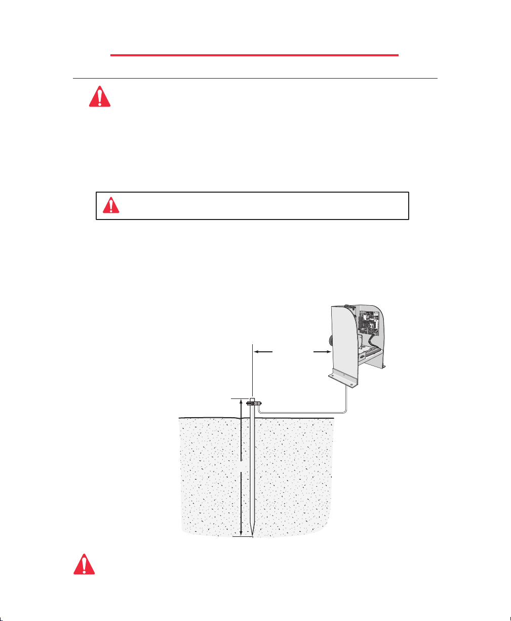
STEP 5: Earth Ground Rod Installation
An earth ground rod must be installed to protect this operator
Proper grounding gives an electrical charge, such as from an electrical static discharge or a near
lightning strike, a path from which to dissipate its energy safely into the earth.
Without this path, the intense energy generated by lightning could be directed towards the Elite gate
operator. Although nothing can absorb the tremendous power of a direct lightning strike, proper
grounding can protect the gate operator in most cases.
Before digging more than 18" deep, contact local underground utility locating companies.
Avoid damaging gas, power, or other underground utility lines.
The earth ground rod must be located within 3 feet from the Elite gate operator. Use the proper type
earth ground rod for your local area.
The ground wire must be a single, whole piece of wire. Never splice two wires for the ground wire. If
you should cut the ground wire too short, break it, or destroy its integrity, replace it with a single wire
length.
C
H
E
C
K
F
U
S
E
C
H
A
R
G
I
N
G
B
O
A
R
D
P
O
W
E
R
P
O
W
E
R
S
Y
S
T
E
M
O
N
J
2
A
L
A
R
M
R
E
V
E
R
S
E
S
E
N
S
O
R
S
E
N
S
O
R
O
H
V
E
E
A
R
V
L
Y
O
A
D
G
A
T
E
P
O
W
E
R
CH
ARG
E OK
BA
T
T
ER
Y
L
O
W
D
C
O
P
E
OPEN
R
AT
O
R
RELA
v
5
M
Y
M
A
D
E
I
N
U
S
A
C
LO
SE RELA
Y
C
E
N
T
R
A
L
C
O
N
T
R
O
L
F
I
R
E
D
E
P
T
S
T
R
I
K
E
O
P
E
N
U
P
P
W
T
I
M
E
R
S
A
F
E
T
Y
L
O
O
P
O
N
6
0
E
X
I
T
0
L
O
O
P
O
F
F
R
A
D
I
O
R
E
C
O
P
E
N
T
O
R
I
G
H
T
1
W
2
S
Y
L
S
P
A
P
L
U
C
S
R
O
I
E
D
V
I
A
E
R
C
E
R
N
N
E
O
P
T
O
T
E
U
K
B
I
R
H
T
S
S
U
P
T
H
P
C
E
T
I
D
W
E
S
R
I
F
Y
E
K
T
I
P
X
O
E
O
L
Y
T
E
P
F
O
A
O
S
L
T
U
P
N
I
C
A
R
V
E
8
W
1
O
Within 3 ft
P
Single Piece of
12 gauge wire
8 ft
Elite Access Systems is not responsible for improper installation or failure to
comply with all necessary local building codes.
13
Page 15
STEP BY STEP INSTALLATION
®
POWER INPUT
18 VAC
POWER INPUT
18 VAC
R
®
ACCESS SYSTEMS INCACCESS SYSTEMS INCACCES S SYS TEM S INC
–
AC AC
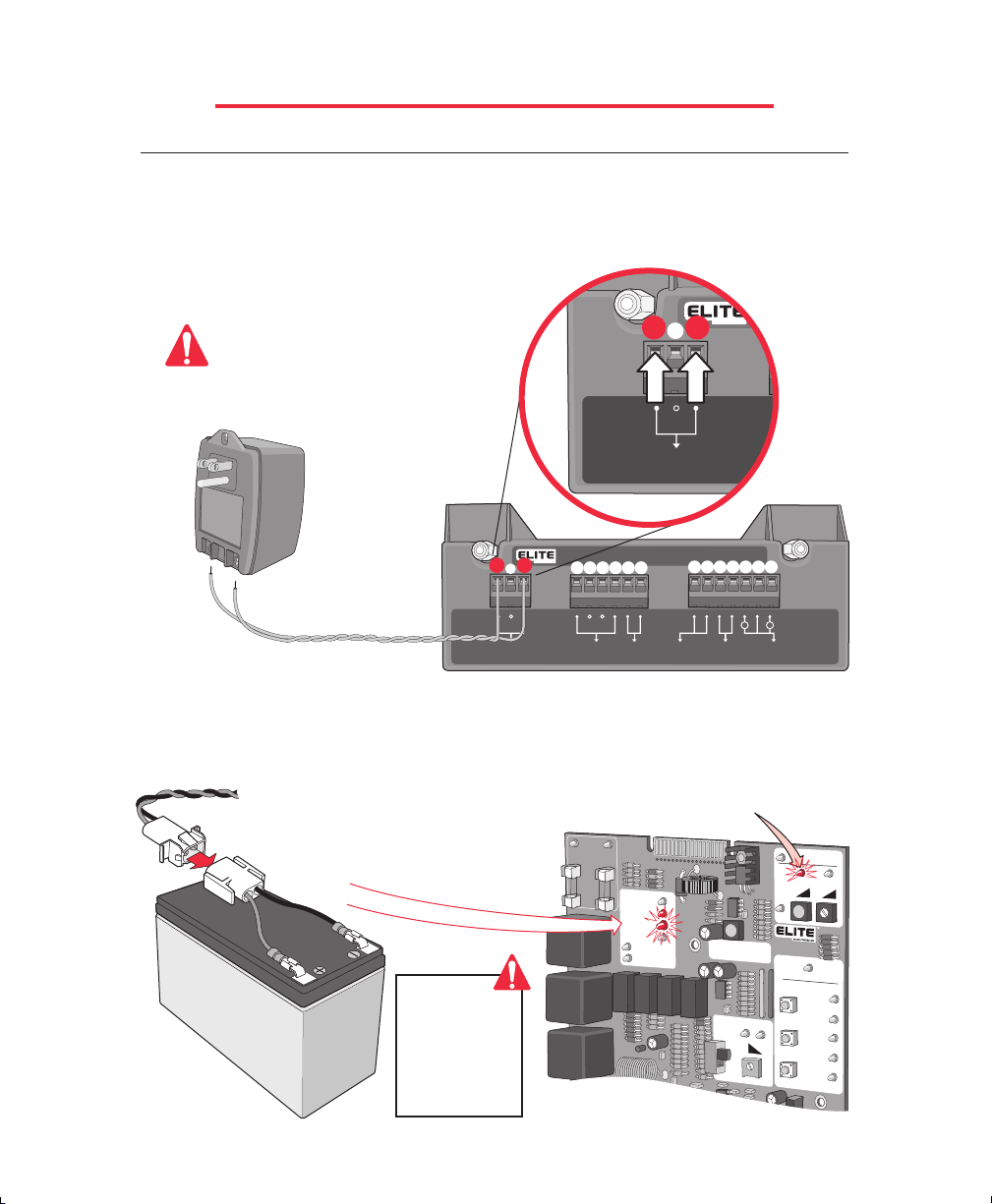
Step 6: DC Power Supply Connection
Use Elite's optional 18 VAC plug-in transformer (Elite Part # A POW-1). Hook up the
transformer to 115 VAC. Use two, low voltage, 14 gauge / 300watt direct burial, landscape
lighting cables. Hook these wires to the plug-in transformer and to the power input
connection on the surge suppressor. Polarity does not matter.
–
LOW LOW
VOLTAGE VOLTAGE
ONLY!ONLY!
®
®
ROBO SURGE SUPPRESSOR
ACCESS SYSTEMS INCACCESS SYSTEMS INCACCESS SYS TE MS INC
––
1 654
7 1312111098
P/N Q412
P/N Q412
PATENT PENDING
PATENT PENDING
CAUTION
To
115 VAC
Do Not use solar panel and plug-in
transformer at the same time.
18 VAC Plug-in
Transformer
AC AC
Maximum Wire Length
14 Gauge Wires
should not exceed 1000 ft.
Polarity Does Not Matter
POWER INPUT
POWER INPUT
18 VAC
18 VAC
SAFETY
SAFETY
LOOP
LOOP
EXIT
EXIT
LOOP
LOOP
FIRE DEPT
FIRE DEPT
KEY SWITCH
KEY SWITCH
STRIKE OPEN
STRIKE OPEN
PUSH BUTTON
PUSH BUTTON
––
++
RADIO
RADIO
RECEIVER
RECEIVER
When the plug-in transformer has been connected to the power source, connect the battery
cable plug to the motor harness plug. You will hear 3 beeps. After the beeps, check the
“Charge OK” LED......it must be “ON”.
Alarm Sensor LED will flash 3 times
during power connection. This means
the board is OK.
CHECK
FUSE
CHARGING
BOARD
POWER
POWER
OVERLOAD
P
O
W
E
R
CH
CHARGE OK
AR
G
BATTERY LO
OPEN RELA
CLOSE RELA
J2
H
E
A
V
Y
G
A
T
E
E O
K
W
Y
Y
TIMER
D
C
O
P
E
R
MADE IN USA
CENTRAL CONTROL
N
E
P
O
UP
PW
P
O
T
S
ON
60
0
E
S
O
OFF
L
C
Motor Harness
Beep!
Beep!
Beep!
Battery
Connected Only:
Power LED on
Transformer
Connected Only:
Power LED on
Charge OK LED on
14
CLASS 2
CLASS 2
SUPPLY
SUPPLY
S
Y
S
T
E
M
A
L
A
R
M
S
E
N
S
O
R
A
T
O
R
v
5
M
F
IR
D
E
S
T
O
P
S
A
L
O
E
X
L
O
R
A
R
E
O
N
R
E
V
E
R
S
E
S
E
N
S
O
R
E
P
T
R
IK
E
E
N
F
E
T
Y
O
P
IT
O
P
D
IO
C
Page 16

STEP BY STEP INSTALLATION
®
POWER INPUT
18 VAC
POWER INPUT
18 VAC
R
®
ACCESS SYSTEMS INCACCESS SYSTEMS INCACCES S SYS TEM S INC
–
AC AC
STEP 7: Optional Solar Panel Connection
If you use Elite's optional solar panel (Elite Part # Solar 3). Connect the two wires from the
solar panel to the power input connection on the surge suppressor (Polarity does not
matter). Sunlight will energize the batteries through the solar panel. This solar panel will
charge up to 1000 Mamp/Hr in optimum conditions & 300 Mamp/Hr in light overcast
conditions. For further details about Elite's solar panel, consult the “Solar 3” Installation
sheet that is included with the solar panel.
Do Not use solar panel and plug-in
transformer at the same time.
CAUTION
Solar Panel
(Elite Part # SOLAR 3)
No Stand
®
AC AC
–
®
ROBO SURGE SUPPRESSOR
ACCESS SYSTEMS INCACCESS SYSTEMS INCACCESS SYS TE MS INC
––
1 654
7 1312111098
P/N Q412
P/N Q412
PATENT PENDING
PATENT PENDING
++
––
CLASS 2
Polarity Does
Not Matter
POWER INPUT
POWER INPUT
18 VAC
18 VAC
SAFETY
SAFETY
LOOP
LOOP
EXIT
EXIT
LOOP
LOOP
FIRE DEPT
FIRE DEPT
KEY SWITCH
KEY SWITCH
STRIKE OPEN
STRIKE OPEN
PUSH BUTTON
PUSH BUTTON
RADIO
RADIO
RECEIVER
RECEIVER
CLASS 2
SUPPLY
SUPPLY
Energizing this operator with solar power only needs the radio receiver to operate the gate.
The only recommended external devices other than radio receivers are dry-contact
command devices which do not consume any current like key switches. Using other
devices that consume high current such as telephone access, magnetic locks or loop
detectors will cause excess drainage of the battery and eventually completely drain the
battery .
Elite recommends using a larger battery
(12 VDC, 30 AHr) (Elite Part # A 12330)
CAUTION
in this operator when using the optional
solar panel.
12 VDC
30 AHr
For More Details,
contact your Local Dealer
15
Page 17

STEP BY STEP INSTALLATION
STEP 8: Surge Suppressor Terminal Connections
The radio receiver must be 12 VDC only (Elite Part # A 1099-12V). If you want to use safety
or exit loops, you must use 12 VDC loop detectors only (Elite Part # A 23).
®
To
115 VAC
Plug-In Transformer
18 VAC
Polarity does
NOT Matter
AC
AC
AC AC
–
POWER INPUT
POWER INPUT
18 VAC
18 VAC
®
ROBO SURGE SUPPRESSOR
ACCESS SYSTEMS INCACCESS SYSTEMS INCACCESS SYS TE MS INC
–
–
1 654
SAFETY
SAFETY
LOOP
LOOP
EXIT
EXIT
LOOP
LOOP
FIRE DEPT
FIRE DEPT
KEY SWITCH
KEY SWITCH
7 1312111098
STRIKE OPEN
STRIKE OPEN
PUSH BUTTON
PUSH BUTTON
P/N Q412
P/N Q412
PATENT PENDING
PATENT PENDING
––
++
RADIO
RADIO
RECEIVER
RECEIVER
13
11
CLASS 2
CLASS 2
SUPPLY
SUPPLY
++
Red Radio (+12 VDC)
Grey Radio (Relay)
12
Black Radio (-)
––
––
Grey Radio (Relay)
11
4 Wire -12 VDC
Radio Receiver
1
4
External “Safety” Loop Detector
12 VDC
1
4
Photo Beam (Safety)
12 VDC
5
6
External “Exit” Loop Detector
12 VDC
16
Card
10
Reader
9
Push
10
Button
9
Phone
10
9
Entry
1
2
3
4
5
6
7
8
9
H
E
L
P
0
Fire or
Any Key
8
Switch
7
Page 18

STEP BY STEP INSTALLATION
STEP 9: Adjusting Gate Travel Distance
Adjustment is done by limit switches which are located on the Robo Slide chassis. By
pressing the plate down and spinning the adjustment nuts, set your limit switches for open
and close cycles.
Limit Switches
Each notch of the nut indicates an
estimated 1 inch of gate travel
STEP 10: Timer
If you want to use the automatic close for the gate system, the timer switch should be set
to the “ON” position. If you want to use the push open or push close command, the timer
should be set to the “OFF” position.
Set Timer
0 to 60 seconds
TIMERTIMER
ONON
OFF
TIMERTIMER
ON
OFFOFF
6060
CHECK
FUSE
CHARGING
BOARD
POWER
POWER
UP
PW
STOP
0
CLOSE
UP
PW
OVERLOAD
POWER
CHARGE OK
BATTERY LOW
OPEN RELA
CLOSE RELA
O
J2
Y
Y
TIMER
ON
OFF
P
E
N
T
O
R
IG
H
T
STOP
60
0
S
Y
S
T
E
M
O
N
A
L
A
R
M
R
E
V
E
R
S
E
S
E
N
S
O
R
S
E
N
S
O
R
H
E
A
V
Y
G
A
T
E
D
C
O
P
E
R
A
T
O
R
v
5
M
M
ADE IN USA
CENTRAL CONTR
OL
F
IR
E
D
E
P
N
T
E
P
O
S
T
R
IK
E
O
P
E
UP
PW
60
N
P
S
A
F
E
T
Y
O
T
L
O
O
P
S
E
X
IT
0
L
O
O
P
E
S
O
L
R
A
D
IO
C
R
E
C
W1
CLOSE
17
Page 19

STEP BY STEP INSTALLATION
STEP 11: Two-Way Adjustable Reversing Sensor
Adjust the “Reverse Sensor” pot on the upper portion of the control board. Do Not Touch
Alarm Sensor pot.
The level of reverse sensitivity depends on the weight of the gate
and the condition of installation.
Too sensitive = if the gate stops or reverses by itself.
Not sensitive enough = if the gate hits an object and does not stop or reverse.
CHECK
FUSE
C
H
A
R
G
I
N
Do Not Touch
Alarm Sensor
Pot
Minimum
Sensitivity
Maximum Sensitivity
HEAVY
GATE
SYSTEM ON
REVERSEREVERSE
A
L
A
R
M
S
E
N
S
O
R
SENSORSENSOR
G
B
O
A
R
D
P
O
W
E
R
P
O
W
E
R
J2
O
V
E
R
L
O
A
D
P
O
W
E
R
C
H
A
R
G
E
O
K
B
A
T
T
E
R
Y
L
O
W
O
P
E
N
R
E
L
A
Y
C
L
O
S
E
R
E
L
A
Y
O
PEN
T
O
RIG
HT
SYSTEM ON
A
L
A
R
M
R
E
S
E
N
S
O
R
S
E
H
E
A
V
Y
G
A
T
E
D
C
O
P
E
R
A
T
O
R
v
5
M
MADE IN USA
C
E
N
T
R
A
L
C
O
N
T
R
F
IR
E
N
D
E
P
T
E
P
O
S
T
R
IK
O
P
E
N
UP
PW
TIMER
P
S
A
F
E
T
O
T
L
O
O
P
S
ON
60
E
X
IT
0
L
O
O
P
E
S
O
OFF
L
R
A
D
IO
C
R
E
C
Important Note!
V
E
R
S
E
N
S
O
R
There is a “Heavy Gate”
LED which will light up
O
L
when the gate is heavier
E
than normal. This is a
Y
diagnostic LED and the
operator will still
1
W
function normally when
this indicator is on.
STEP 12:
Warning placards need to be permanently mounted on BOTH sides of the gate.
For Toll Free
Technical Support:
1-888-ELITE-10
NOW YOUR INSTALLATION IS COMPLETE
18
35483
Page 20

“OPTIONAL” FIRE RELEASE BOX
The “Fire Release Box”, is designed for use on sliding gates. It consists of a plated box,
with doors on the front and back. The doors can be locked with your own padlock, or the
fire department's padlock. The fire box would be fixed to the gate pickets. It can be opened
from either side of the gate. A steel cable with a t-handle runs from the box to the release
mechanism at the rear end of the chain. We do not provide the 1/2" EMT to run the cable
through. The release mechanism, is placed where the chain bolt would normally be. when
you pull on the t-handle, you release the chain from the bolt. To reset, simply reinsert the
pin into the housing for normal operation. (Elite Part # A CP-17)
Contact your local dealer
for more information.
The chain is held in place by a spring loaded pin.
Pull firmly on the
“T” Handle to release
the chain.
19
Page 21

“OPTIONAL” INPUT BOARD
The optional board allows extra control of the gate, is available only from Elite Access
Systems. Installation is simple; just clip the optional board to the J2 slot on the top of the
control board. Below lists the function of each pin.
1
&
2
Open Switch (N.O.)
3 & 4
5 & 6
7 & 8
9 &10
11
12 & 7
13 & 14
15 & 16
1
3
2
4
Stop Switch (N.C.) (Cut W1 Jumper at Bottom of Board)
Timer Close Output to Slave
Timer Input from Master (Close Command or Close Switch) (N.O.)
Alarm Output will be set off with very heavy gates or object preventing gate operation.
d
(Not Burglar Alarm) (9 = +12 VDC, 10 = Alarm)
&
4
Emergency Open Switch (Direct Command from Battery to Motor)
Emergency Close Switch (Direct Command from Battery to Motor)
Magnetic Lock - Dry Contact Relay (13 = Com, 14 = N.C.)
Center Loop Option (For Swing Gate Operators Only)
5
7
9
11
13
15
6
8
10
12
14
16
16-Pin Plug
W1
CHARGING
POWER
CHECK
FUSE
BOARD
POWER
OVERLOAD
POWER
CHARGE OK
BAT
TERY LOW
OPEN RELAY
CLOSE RELAY
J2
20
SYSTEM ON
A
LA
R
M
SEN
SO
R
H
EA
VY
G
ATE
DC OPERATOR v 5M
MADE IN USA
CENTRAL CONTROL
OPEN
DEPT
FIRE
REVER
SE
NSO
SE
R
Page 22

MAGLOCK WIRING CONNECTION
The “Optional” input board MUST be used to perform this function. (Elite Part#
Elite Part # A MG 1300
Dry Contact Relay
Relay Contact Rating
0.5 Amp - 125 VAC
1 Amp - 24 VDC
14
13
1
3
5
7
11
9
13
15
N.C.
Common
Power
for
Maglock
Q203
)
2
4
6
8
10
12
14
16
16-Pin Plug
CHECK
FUSE
CHARGING
POWER
BOARD
POWER
SYSTEM ON
J2
A
LA
R
M
R
EVER
R
FIR
DEPT
SE
SEN
SO
R
E
OVERLOAD
POWER
CHARGE OK
BAT
TERY LOW
OPEN RELAY
CLOSE RELAY
21
SEN
SO
H
EAVY
G
A
TE
DC OPERATOR v 5M
MADE IN USA
CENTRAL CONTROL
OPEN
Page 23

“OPTIONAL” 12 VDC PHOTO BEAM WIRING
AC AC
–
POWER INPUT
POWER INPUT
18 VAC
18 VAC
®
ROBO SURGE SUPPRESSOR
ACCESS SYSTEMS INCACCESS SYSTEMS INCACCESS SYS TE MS INC
––
1 654
SAFETY
SAFETY
LOOP
LOOP
EXIT
EXIT
LOOP
LOOP
FIRE DEPT
FIRE DEPT
KEY SWITCH
KEY SWITCH
7 1312111098
STRIKE OPEN
STRIKE OPEN
PUSH BUTTON
PUSH BUTTON
P/N Q412
P/N Q412
PATENT PENDING
PATENT PENDING
––
–
++
+
RADIO
RADIO
RECEIVER
RECEIVER
CLASS 2
CLASS 2
SUPPLY
SUPPLY
®
BlueOrange White Brown
(Elite Part # A OMRON 12V) (Failsafe)
4
1
11 13
Power
Photo Beam (Safety) 12 VDC
It is best to use 12 VDC Failsafe Photo Beam Sensors for this Safety Option
Failsafe Photo Beam: If a failsafe photo beam is not working or loses power or photo beam
is blocked, then the photo beam will stop
all gate operation.
Important: If photo beam
is blocked the gate will
stop and reopen. The gate
will remain open until the
obstruction is cleared.
Contact your local dealer
for more information.
22
Page 24

3–PUSH BUTTON WIRING CONNECTION
The “Optional” input board MUST be used to perform this function. (Elite Part#
There can be NO common wires within this
3-push button station.
2
4
8
5
1
2
7
3
4
6
11
9
13
8
10
12
14
16
16-Pin Plug
C
Cut W1 jumper at the
bottom of Board to use the
stop button in the 3-push
button station
W1
15
H
P
N.C.
C
H
E
C
K
F
U
S
E
A
R
G
I
N
G
B
O
A
R
D
O
W
E
R
P
O
W
E
R
OVERLOAD
POWER
C
B
H
A
R
GE O
ATTERY LOW
O
CLO
J
2
K
PEN
R
ELAY
SE R
ELAY
Open-N.O. Contact
Stop-N.C. Contact
Close-N.O. Contact
1
3
7
UP
PW
TIM
ER
ON
60
0
OFF
H
E
A
V
Y
G
A
T
E
D
C
O
P
E
R
MADE IN USA
CENTR
OPEN
STOP
CLOSE
SYSTEM ON
A
L
A
S
E
N
A
T
O
R
R
M
S
O
v
AL CO
Q203
)
R
E
V
E
R
S
E
R
S
E
N
S
O
R
5
M
N
TR
O
L
F
IR
E
D
E
P
T
S
T
R
IK
E
O
P
E
N
S
A
F
E
T
Y
L
O
O
P
E
X
IT
L
O
O
P
R
A
D
IO
R
E
C
O
P
23
E
N
T
O
R
IG
H
T
1
W
Page 25

3–PUSH BUTTON WIRING MASTER/SLAVE
The “Optional” input board
Part#
Q203
). A 12 VDC Double Pull Double Throw (DPDT) 3 Amp Minimum Relay must be
used (Not Included).
®
AC AC
–
POWER INPUT
POWER INPUT
18 VAC
18 VAC
ACCESS SYSTEMS INCACCESS SYSTEMS INCACCESS SYS TEM S INC
®
ROBO SURGE SUPPRESSOR
––
1 654
SAFETY
SAFETY
EXIT
EXIT
LOOP
LOOP
LOOP
LOOP
1
5
3
7
2
4
6
8
16-Pin Plug
FIRE DEPT
FIRE DEPT
KEY SWITCH
KEY SWITCH
9
10
7 121098
STRIKE OPEN
STRIKE OPEN
PUSH BUTTON
PUSH BUTTON
11
12
P/N Q412
P/N Q412
PATENT PENDING
PATENT PENDING
11
–
––
13
14
13
+
++
RADIO
RADIO
RECEIVER
RECEIVER
16
15
CLASS 2
CLASS 2
SUPPLY
SUPPLY
MUST
be used on both operators to perform this function (Elite
There can be NO common wires
within this 3-button station.
1
3
Open-N.O. Contact
Stop-N.C. Contact
Close-N.O. Contact
2
4
1
2
DPDT
12 VDC
Relay
3 Amp Minimum
5
3
4
6
8
Com
Com
NO
NO
–
+
+
Com
11
12
14
13
11
N.O.
–
8
7
15
16
13
9
7
10
16-Pin Plug
7
8
N.O.
Com
C
H
E
C
K
F
U
S
E
C
H
A
R
G
I
N
G
B
O
A
R
D
P
O
W
E
R
P
O
W
E
R
J
2
OVE
RLOAD
POWER
C
H
A
R
G
E
O
K
B
A
T
T
E
R
Y
L
O
W
O
P
E
N
R
E
L
A
Y
C
L
O
S
E
R
E
L
A
Y
O
P
E
N
T
O
R
IG
H
T
S
Y
S
T
E
M
O
N
ALARM
SEN
SOR
HE
AVY
G
ATE
D
C
O
P
E
R
A
T
O
R
v
5
M
M
A
D
E
IN
U
S
A
C
E
N
T
R
A
L
C
F
D
OPEN
S
O
U
P
P
W
T
IM
E
R
S
L
STOP
O
N
6
0
E
0
L
R
CLOSE
O
F
F
R
The timers
REVER
SE
SENS
OR
be turned
BOTH
O
N
T
R
O
L
I
R
E
E
P
T
T
R
I
K
E
P
E
N
A
F
E
T
Y
O
O
P
X
I
T
O
O
P
A
D
I
O
E
C
MUST
OFF
operators.
on
W1
W1
C
H
E
C
K
F
U
S
E
C
H
A
R
G
I
N
G
B
O
A
R
D
P
O
W
E
R
P
O
W
E
R
J
2
OVE
RLOAD
POWER
C
H
A
R
G
E
O
K
B
A
T
T
E
R
Y
L
O
W
O
P
E
N
R
E
L
A
Y
C
L
O
S
E
R
E
L
A
Y
O
P
E
N
T
O
R
IG
H
T
S
Y
S
T
E
M
O
N
ALARM
REVER
SE
SEN
SOR
SENS
OR
HE
AVY
G
ATE
D
C
O
P
E
R
A
T
O
R
v
5
M
M
A
D
E
IN
U
S
A
C
E
N
T
R
A
L
C
O
N
T
R
O
L
F
I
R
E
D
E
P
T
OPEN
S
T
R
I
K
E
O
P
E
N
U
P
P
W
T
IM
E
R
S
A
F
E
T
Y
L
O
O
P
STOP
O
N
6
0
E
X
I
T
0
L
O
O
P
R
A
D
I
O
CLOSE
O
F
F
R
E
C
W1
Cut W1 jumper at the
bottom of each board to
use the stop button in
the 3-push button station
24
Page 26

OPTIONAL EDGE SENSOR WIRING
®
AC AC
–
POWER INPUT
POWER INPUT
18 VAC
18 VAC
®
ROBO SURGE SUPPRESSOR
ACCESS SYSTEMS INCACCESS SYSTEMS INCACCESS SYS TE MS INC
––
1 654
SAFETY
SAFETY
LOOP
LOOP
EXIT
EXIT
LOOP
LOOP
1 4
FIRE DEPT
FIRE DEPT
KEY SWITCH
KEY SWITCH
7 1312111098
STRIKE OPEN
STRIKE OPEN
PUSH BUTTON
PUSH BUTTON
P/N Q412
P/N Q412
PATENT PENDING
PATENT PENDING
––
++
RADIO
RADIO
RECEIVER
RECEIVER
CLASS 2
CLASS 2
SUPPLY
SUPPLY
• Never Paint Sensing Edge
• Never Pull On Wires
• Never Cut or Puncture Edge
• Never Operate Unguarded Equipment
Use #10 Screws as necessary to mount Edge Sensor
Contact your local dealer
for more information.
Miller Edge Models: MGR20 or MGS20
25
Page 27
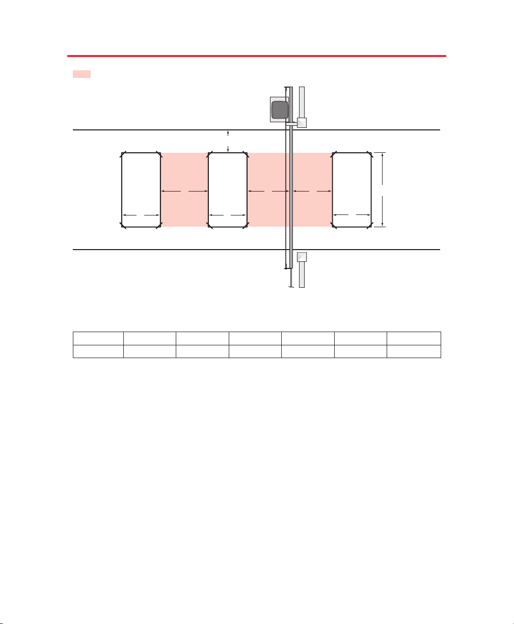
SINGLE OPERATOR LOOP SIZE AND PLACEMENT
It is VERY important to have enough separation between loops and gates to prevent false detection.
If A =
Then C =
6 Feet
4 Feet
9 Feet
4.5 Feet
12 Feet
5 Feet
15 Feet
5 Feet
18 Feet
5.5 Feet
21 Feet
6 Feet
This is for a typical single Robo Slide loop installation. Individual circumstances may alter dimensions.
For toll free technical support: 1-888-ELITE-10
Maximum gate length for Robo Slide is 20 Feet.
As
A increases in size to cover a larger gate opening, the gate will cause a larger change of inductance when
opening and closing. Therefore dimension C must increase as A increases.
If the Inside and outside safety loop are connected to the same loop detector they should be series connected.
Dimension
A, B and C should be the same for each loop. Both loops should have the same number of turns of
wire.
Dimension
D should be equal to or greater than the larger of the “Inside Safety Loop” or “Exit Loop's”
dimension B.
Out
In
Inside
Safety
Loop
Outside
Safety
Loop
Exit
Loop
A
B
BB
CCD
Drawing not to scale
4 Feet
35483
26
Page 28

If A =
Then C =
6 Feet
4 Feet
9 Feet
4.5 Feet
12 Feet
5 Feet
15 Feet
5 Feet
18 Feet
5.5 Feet
28 Feet
6 Feet
Maximum gate length for each Robo Slide is 20 Feet.
As
A increases in size to cover a larger gate opening, the gate will cause a larger change of inductance when
opening and closing. Therefore dimension C must increase as A increases.
If the Inside and outside safety loop are connected to the same loop detector they should be series connected.
Dimension
A, B and C should be the same for each loop. Both loops should have the same number of turns of
wire.
Dimension
D should be equal to or greater than the larger of the “Inside Safety Loop” or “Exit Loop's”
dimension B.
MASTER/SLAVE LOOP SIZE AND PLACEMENT
It is VERY important to have enough separation between loops and gates to prevent false detection.
Out
In
Inside
Safety
Loop
Outside
Safety
Loop
Exit
Loop
A
B
B B
D
CC
Drawing not to scale
This is for a typical master/slave loop installation. Individual circumstances may alter dimensions.
For toll free technical support: 1-888-ELITE-10
4 Feet
35483
27
Page 29
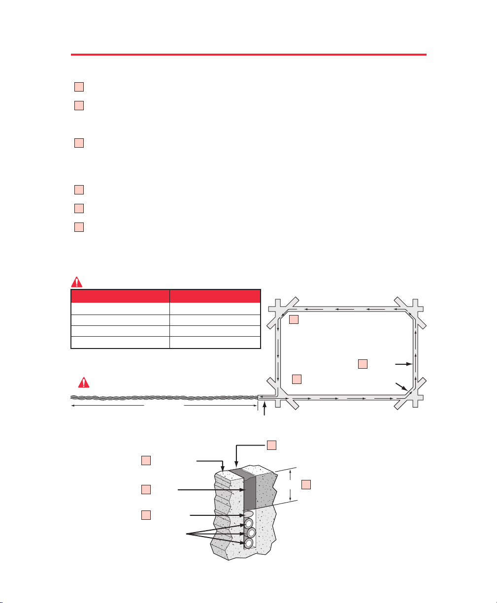
Loop Installation “Saw Cut” Type
LOOP INSTALLATION AND NUMBER OF WIRE TURNS
Mark the loop layout on the pavement. Remove sharp inside corners that can damage the loop wire
insulation.
Set the saw to cut to a depth (typically 2" to 2.5") that insures a minimum of 1" from the top of the wire to
pavement surface. The saw cut width should be larger than the wire diameter to avoid damage to the wire
insulation when placed in the saw slot. Cut the loop and feeder slots. Remove all debris from the slot with
compressed air. Check that the bottom of the slot is even.
It is highly recommended that a continuous length of wire be used to form the loop and feeder to the
detector. It is also highly recommend using 12-18 AWG cross-link polyethylene (XLPE) insulation for the
loop wire. Use heavier wire gauge for a more durable loop area. Use a wood stick or roller to insert the wire
to the bottom of the saw cut (Do not use sharp objects). Wrap the wire in the loop saw cut until the desired
number of turns is reached. Each turn of wire must lay flat on top of the previous turn.
The wire must be twisted together a minimum of 6 twists per foot from the end of the saw cut to the
detector.
the wire must be held firmly in the slot with 1" pieces of backer rod every 1 to 2 feet. This prevents the wire
from floating when the loop sealant is applied.
Apply the sealant. The sealant selected should have good adhering properties with similar expansion and
contraction characteristics to that of the pavement material.
Number of Wire Turns Needed for Loop
1
2
2
3
4
5
6
6
6
5
5
10 feet to 13 feet
14 feet to 26 feet
27 feet to 80 feet
80 feet and up
Loop Perimeter
Important
Number of Wire Turns
4
3
2
1
The wire is continuously wound
in the loop saw cut for the
required number of turns. One
turn shown. (Refer to table)
The wire must be twisted together 6 twists per foot
from the end of the saw cut to the loop detector.
Remove sharp inside corners
by making corner cuts
Saw Cut
Home Run
Feeder Slot
Sealant
Backer Rod
Insulated Loop Wire
3 turns Shown, amount varies.
Refer to table
Recommended Loop Wire
XLPE 12-18 gauge
(Use heavier wire gauge for a
more durable loop area)
Min 1"
1/8" to 1/4" Width,
2" to 2.5" Depth Saw Cut
Road Surface
1
2
3
28
Page 30

WIRING LOOP DETECTOR TO OPERATOR
®
11
13
1
4
AC AC
–
POWER INPUT
POWER INPUT
18 VAC
18 VAC
®
ROBO SURGE SUPPRESSOR
ACCESS SYSTEMS INCACCESS SYSTEMS INCACCESS SYS TE MS INC
––
1 654
SAFETY
SAFETY
LOOP
LOOP
EXIT
EXIT
LOOP
LOOP
FIRE DEPT
FIRE DEPT
KEY SWITCH
KEY SWITCH
7 1312111098
STRIKE OPEN
STRIKE OPEN
PUSH BUTTON
PUSH BUTTON
P/N Q412
P/N Q412
PATENT PENDING
PATENT PENDING
––
–
++
RADIO
RADIO
RECEIVER
RECEIVER
+
CLASS 2
CLASS 2
SUPPLY
SUPPLY
External 12 VDC “Safety” Loop
Detector - Allows gate to stay open
when vehicles are obstructing gate path.
INSIDE
SAFETY
LOOP
EXIT
LOOP
IN
13
11
6
5
External 12 VDC “Exit” Loop Detector -
Allows gate to automatically open for
exiting vehicles.
OUT
O
UTSIDE
SAFTEY
LOOP
If the “Inside” and “outside” safety loops are connected to the same loop detector:
• They should be series connected to the detector
• Have the same dimensions. (Page 26 or 27)
• Have the same number of wire turns. (Page 28)
29
Page 31

MASTER AND SLAVE WITH TIMER
To use the master/slave option with Robo Slide, you must purchase the Optional Input
Board (Elite Part # Q203) and connect it to the J2 slot of each operator. (Refer to page 20)
Caution: 18 VAC plug-in transformer, per gate operator required
Master Slave
Use 16-18 Gauge Wires Connect Gate Operators Together
1
5
1
7
3
8
4
6
2
Master J2 Plug
15
13
11
9
16
14
12
10
Master Pin 1 to Slave Pin 1
Master Pin 2 to Slave Pin 2
Master Pin 5 to Slave Pin 7
Master Pin 6 to Slave Pin 8
7
3
5
9
11
13
15
4
6
10
12
14
2
8
16
Slave J2 Plug
1. Make master/slave J2 plug connections as shown above
2. Turn timers on BOTH control boards to the “ON” position
3. Use MASTER timer ONLY for the auto close time adjustment (0 to 60 sec)
4. Turn the SLAVE timer adjustment all the way Counterclockwise
Set Timer
0 to 60 seconds
Master Timer “ON”
TIMERTIMER
UP
PW
ONON
6060
OFF
STOP
0
CLOSE
Slave Timer “ON”
TIMERTIMER
UP
ONON
60
OFF
Maximum
Counterclockwise
Setting
30
PW
STOP
0
CLOSE
Page 32

MASTER AND SLAVE WITHOUT TIMER
To use the master/slave option with Robo Slide, you must purchase the Optional Input
Board (Elite Part # Q203) and connect it to the J2 slot of each operator. (Refer to page 20)
Caution: 18 VAC plug-in transformer, per gate operator required
Master Slave
Use 16-18 Gauge Wires Connect Gate Operators Together
1
7
5
3
8
6
4
2
Master J2 Plug
1
15
13
11
9
16
14
12
10
Master Pin 1 to Slave Pin 1
Master Pin 2 to Slave Pin 2
3
4
2
1. Make master/slave J2 plug connections as shown above
2. Turn timers on BOTH control boards to the “OFF” position
Master Timer “OFF” Slave Timer “OFF”
TIMERTIMER
ON
OFFOFF
UP
PW
60
STOP
0
CLOSE
TIMERTIMER
ON
OFFOFF
UP
PW
60
0
5
7
9
11
6
8
10
12
Slave J2 Plug
STOP
CLOSE
13
15
14
16
31
Page 33

CONTROL BOARD FUNCTIONS
1
Power On LED
2
Charge On LED
3
Low Battery Indicator LED
4
Heavy Gate Indicator LED
5
Open Relay LED
6
Close Relay LED
7
System on, Reversing Sensor and Alarm Sensor
8
Alarm Sensor LED
9
Reversing Sensor LED (Rebounder)
1010
Central Control LED
1111
Fire Department or Key Switch LED
1212
Strike Open LED
1313
Safety Loop or Photocell LED
1414
Exit Loop LED
1515
Radio Receiver LED
2020
CHECK
FUSE
CHARGING
BOARD
POWER
2626
2525
POWER
O
V
E
R
P
O
W
1
2
E
C
H
A
R
B
A
T
T
3
5
6
L
O
A
D
R
G
E
O
K
E
R
Y
L
O
W
O
P
E
N
R
E
L
C
L
O
S
E
R
E
L
OPEN TO RIGHT
J2
A
Y
A
Y
TIM
1616
Timer Power LED
1717
Timer-Up Indicator
1818
J2 Alternate Optional Output
1919
Movement Direction Sockets
2020
Replace Fuse Indicator
2121
Spike Suppressor
2222
Jumper for Stop Button
2323
Optional Input Board
24 24
Surge Suppressor Connector
2525
Breaker Reset
2626
Overload LED
2727
On Board Open Button
2828
On Board Stop Button
2929
On Board Close Button
2323
1818
7
8
9
H
EAVY
G
A
TE
SYSTEM ON
ALA
RM
R
EV
ERSE
SEN
SO
R
SEN
SO
R
4
1010
DC O
PERAT
OR v 5M
MADE IN USA
CENTRAL CONTR
OPEN
U
P
P
W
E
R
O
N
60
O
FF
STOP
0
CLOSE
FIRE
DEPT
STRIKE
OPEN
SAFETY
LOOP
EXIT
LOOP
RADIO
REC
OL
2727
2828
1111
1212
1313
1414
1515
2929
1616
1717
W1
22221919
2121
2424
32
Page 34

LED DESCRIPTION
LED Description LED On LED Off
1
Power at all times when
there is one or more
power sources
ie: Battery, 18 VAC or solar
2
Charger OK on when there
is any charging power
ie: 18 VAC - solar
3
Battery Low
normally off - it will
indicate low battery
4
Heavy Gate
will work only when the
gate is in motion
5
Open Relay
Power source OK and
board power fuse OK
Transformer or solar OK
and charging power fuse OK
Flashing LED - Battery is
less than required limit
needs to be recharged
1. Excess usage
2. Bad charging system
3. Under rate solar panel
4. Bad battery
5. Bad battery connection
1. Gate is too heavy
2. Bad wheels
3. Bad rollers
4. Chain is too tight
5. Steep slope on open or
close cycle
6. Low battery
Open relay is energized
1. No power source at all
If dimmed down
1. Bad board power fuse
1. No Transformer or Solar
If dimmed down
1. Bad Charging power fuse
Battery OK
Battery voltage is over
minimum required limit
Gate weight and
condition are OK
Open relay is not energized
6
Close Relay
7
System On
will work only when the
Detecting motor current
gate is in motion
8
Alarm Sensor
when LED goes on you
will hear a “
beep” sound
for about 20 seconds
LED will flash 3 times for
“board OK” during power
connection.
Note: Circled red numbers indicates location on control board, identified on page 32.
1. Hearing beep sound
means overload
2. Gate is too heavy
3. Broken wheel
4. Gate off track
5. Unwanted object has
physically stopped gate
Close relay is not energizedClose relay is energized
1. Motor stop
2. No motor current detected
System is OK
33
Page 35

LED DESCRIPTION - CONTINUED
LED Description LED On LED Off
9
Reversing Sensor
1010
Central Control
Acknowledgement of
receiving open command
from one of the
surge suppressor terminals
• Fire Department 7
• Strike Open 9
• Safety Loop 1
• Exit Loop 5
• Radio Receiver 11
& 8
& 10
& 4
& 6
& 12
No obstruction is detectedSensor is detecting obstruction
Not receiving any command
1111
Fire Dept
1212
Strike Open
1313
Safety Loop
1414
Exit Loop
1515
Radio Rec
1616
Timer PW
1717
Timer UP
Receiving signal at the surge
suppressor terminal block
7
& 8
Receiving signal at the surge
suppressor terminal block
9
& 10
Receiving signal at the surge
suppressor terminal block
1
& 4
Receiving signal at the surge
suppressor terminal block
5
& 6
Receiving signal at the surge
suppressor terminal block
11
& 12
Not receiving signal at
the surge suppressor
terminal block 7
Not receiving signal at
the surge suppressor
terminal block 9
Not receiving signal at
the surge suppressor
terminal block 1
Not receiving signal at
the surge suppressor
terminal block 5
Not receiving signal at
the surge suppressor
terminal block 11
Timer power is on Timer is not on
Output signal to close relay
Not receiving signal to
close relay
& 8
& 10
& 4
& 6
& 12
Note: Circled red numbers indicates location on control board, identified on page 32.
34
Page 36

TROUBLESHOOTING
How to Reset the Breaker
If all electronic sensors fail or are not adjusted properly due to heavy gates, off-track gate,
or obstructed gate path, the breaker will kick-out. Reset the breaker by pressing the reset
button located on the bottom left corner of the control board.
Always disconnect the battery before
resetting the breaker or injury could
CAUTION
occur as the gate starts.
OPEN TO RIGHT
The breaker reset is located at
the bottom left corner of the
control board as shown
How to Check the Fuses
If the gate is not moving in any direction be sure to check all of the LED displays on the
control board. If the board power or charging power LEDs are “ON”, change the
corresponding fuse on the top left corner of the board.
CHECKCHECK
FUSEFUSE
C
H
A
R
G
IN
G
B
O
A
R
Replace fuse with
CAUTION
1.5A - 250V fuse
Robo Fuse
(Elite Part # Q162)
P
O
W
E
R
P
O
W
35
D
ER
OVERLOAD
POWER
CHARGE OK
BAT
TERY LOW
OPEN RELAY
CLOSE RELAY
J2
H
E
AVY
G
ATE
DC OPE
MAD
Page 37

TROUBLESHOOTING
The Gate Will Not Close!
D
C O
P
ER
A
T
O
R
v 5M
MADE IN USA
CENTRAL CONTROL
FIR
E
DEPT
S
TRIKE
O
PEN
P
PW
O
T
SA
S
E
0
S
O
L
C
Symptom:
The radio receiver LED on the control
board remains “ON” when using the remote
control.
Possible Solutions:
The radio receiver has malfunctioned in the “ON”
position.
The Gate Will Not Open!
PW
0
D
C
O
PE
MADE IN USA
CENTRAL CONTROL
P
O
T
S
E
S
O
L
C
FETY
LO
O
P
EXIT
LO
O
P
RADIO
REC
Stuck remote control button.
RA
T
O
R
v 5M
FIR
E
DEPT
STR
IK
E
O
PEN
SA
FETY
LO
O
P
EXIT
LO
O
P
RADIO
REC
For Toll Free Technical Support: 1-888-ELITE-10
35483
Symptom:
The radio receiver LED on the control
board remains “OFF” when using the remote
control.
Possible Solutions:
Dead battery in the remote
control. Remote control code switches are different
from radio receiver code switches. The radio
receiver has malfunctioned in the “OFF” position.
For further information, contact your local dealer.
36
Page 38

TROUBLESHOOTING
If you hear a “BEEP” sound.......
The gate is TOO Heavy.
ALARM
SENSOR
Debris is on the gate's track such as
mud, rocks, dirt, etc.
ALARM
SENSOR
The gate has one or more broken wheels.
ALARM
SENSOR
After fixing the problem, the Robo Slide will automatically reset itself.
37
The gate is hitting a wall or vehicle.
ALARM
SENSOR
The gate is off the track.
ALARM
SENSOR
Page 39

Q241
Q133
ROBO SLIDE PARTS
Q214
Q162
Q006
Q203
C
H
E
C
K
F
U
S
E
CHARGING
BO
ARD
POWE
R
PO
W
ER
J2
O
VE
R
L
O
A
D
PO
W
ER
C
H
A
R
G
E
O
K
B
A
T
T
E
R
Y
L
O
W
O
P
E
N
R
E
L
A
Y
C
L
O
S
E
R
E
L
A
Y
O
P
E
N
T
O
R
IG
H
T
Robo SW/SL Conversion Kit
S
Y
S
T
E
M
O
N
A
L
A
R
M
R
E
V
E
R
S
E
S
E
N
S
O
R
S
E
N
S
O
R
H
E
A
V
Y
G
A
T
E
D
C
O
P
E
R
A
T
O
R
v
5
M
M
A
D
E
I
N
U
S
A
C
E
N
T
R
A
L
C
O
N
T
R
O
L
F
IR
E
N
D
E
P
T
E
P
O
S
T
R
IK
E
O
P
E
N
U
P
P
W
T
I
M
E
R
P
S
A
F
E
T
Y
O
T
L
O
O
P
S
Q206
O
N
6
0
E
X
IT
0
L
O
O
P
E
S
O
O
L
F
F
R
A
D
IO
C
R
E
C
1
W
Q412
T
U
P
N
I
C
R
A
E
V
W
8
O
1
P
Q214
C
H
E
C
K
F
U
S
E
CHARG
ING
B
OA
RD
POW
ER
POW
ER
O
V
Q206
PO
C
H
B
A
2
S
Y
S
L
A
P
L
P
C
U
S
O
R
I
E
D
V
A
I
R
E
C
E
R
N
E
N
P
O
O
T
T
E
U
K
I
B
R
T
H
S
S
U
P
T
H
P
C
E
T
D
I
E
W
R
I
S
F
Y
E
K
IT
P
X
E
O
O
L
TY
E
P
F
O
A
O
S
L
S
Y
S
T
E
M
O
N
J2
A
L
A
R
M
R
E
V
E
R
S
E
S
E
N
S
O
R
S
E
N
S
O
R
H
E
A
V
Y
E
RL
O
AD
G
A
T
E
W
ER
A
R
G
E
O
K
T
T
E
R
Y
L
O
W
D
C
O
P
E
R
A
T
O
R
O
C
O
v
5
P
E
L
O
P
E
N
M
N
R
E
L
A
Y
M
A
D
E
I
N
U
S
A
S
E
R
E
L
A
Y
C
E
N
T
R
A
L
C
O
N
T
R
O
L
F
I
R
E
N
D
E
P
T
E
P
O
S
T
R
IK
E
O
P
E
N
U
P
P
W
T
I
M
E
R
P
S
A
F
E
TY
O
T
L
O
O
P
S
O
N
6
0
E
X
IT
0
L
O
O
P
E
S
O
O
L
F
F
R
A
D
IO
C
R
E
C
T
O
R
IG
H
T
1
W
Battery
Harness
Q205
Q123
*Q129
A BT 12
A H-110
#41
A H-113 A H-125
*Q003
*Q004
A H-111
#40
Q124
Note: *Sold Individually, 2 Shown.
For part list, refer to next page.
38
Q132
Q412
Q131
Q156
Q137
S
PUT
IN
AC
ER
W
18 V
PO
Q134
*Q101
*Q029
2
Y
ASS
CL
UPPL
S
O
R
ADI
IVE
R
CE
RE
EN
ON
OP
KE
BUTT
STRI
USH
P
T
CH
E DEP
SWIT
FIR
EY
K
IT
P
EX
LOO
AFETY
LOOP
Q180
Q212
*Q032
Q135
Page 40

PARTS LIST
Robo SW / SL Conversion Kit
Q211 - Limit/Motor Harness
Q205
Q412 - Surge Suppressor Terminal
Q206 - Control Board
Battery Harness
A BT 12 - 12 VDC, 7 amp. Battery with Harness
A H-110 - Gate Chain #41 (10 ft) (20 ft included)
A H-111 - Gate Chain #40 (10 ft) Optional
A H-113 - Master Link #41
A H-125 - Master Link #40
Q003 - Chain Bolt
Q004 - Chain Bracket
Q006 - PC Board Nuts (1 Set)
Q029 - Limit Switch
Q032 - Limit Switch Adjustment Nut
Q101 - Limit Switch Bearing Holder
Q123 - Motor - DC - 12V
Q124 - Chassis - Robo Slide
Q129 - Idler Sprocket with Bolt/Nut
Q131 - Limit Switch Drive Sprocket
Q132 - Limit Switch Sprocket
Q133 - Drive Sprocket
Q135 - Limit Switch Bolt (Shaft)
Q137 - Limit Switch Box
Q156 - 1/2 Inch Collar
Q162 - Fuse
Q180 - 1 inch Diameter Coupling
Q203 - Option Board with Harness
Q206 - Control Board
Q212 - Gear Reducer 40 - 30:1
Q214 - Limit/Motor Harness
Q241 - Cover, Polyethylene Robo Slide
Q412 - Surge Suppressor Terminal
Multiple Parts “Q” Number
MAINTENANCE
Make sure the reversing sensor is functioning properly. (Page 18)
Make sure the gate track is clear of dirt, rocks or other substances.
Make sure the wheels are operating smoothly on the track.
Oil the chain regularly with a chain lubrication oil available at most motorcycle stores.
Important: Any service must be performed by an authorized service technician.
Please call your local
service company for
maintenance and repairs.
PLEASE DO NOT TOUCH ME!...UNLESS YOU ARE AN AUTHORIZED SERVICE TECHNICIAN!
39
Page 41

ELITE ROBO SLIDE ACCESSORIES
12 VDC Radio Receiver
(Elite Part # A 1099 12V)
18 VAC Plug-in
Transformer
(Elite Part # A POW 1)
Solar Panel
Transmitter
(Elite Part # A 3089)
12 VDC
Photo Beam
(Elite Part # A OMRON 12V)
Magnetic Locks
(Outdoor)
(Elite Part # A MG 1300)
Power Wheels Series
(Elite Part # SOLAR 3)
12 VDC 30 AHr Battery
12 VDC
30 AHr
(Elite Part # A 12330)
V-Groove
4", 5", 6"
12 VDC External
Loop Detectors
(Elite Part # A 23)
“Exit Loop”
“Center Loop”
“Safety Loop”
40
Page 42

OWNERS CHECKLIST OF INSTALLATION
1.
2.
3.
4.
5.
6.
7.
8.
9.
10.
11.
12.
Owner and Installer must read all warnings and safety precautions and be aware of their
roles and responsibilities. (Pages 2-9)
Make sure concrete mounting pad is big enough and deep enough for operator. (Page 11)
Operator must be securely fastened to concrete pad. (Page 11)
Operator chain must be 4" Minimum from gate. (Page 11)
Chain must not be too tight or too loose.
Gate operator must be grounded to an earth ground rod within 3 feet. (Page 13)
Verify that both the battery and plug-in transformer are connected properly. (Page 14)
Verify that the gate opens and closes as needed. (Page 17)
When gate hits object during operation, it must stop or reverse. (Page 18)
Make sure that any pinch point or potential entrapment are guarded by means of safety
devices or like. (Page 7, 22, 25)
Warning placards need to be permanently mounted on both sides of gate. (Page 18)
Test all additional equipment connected to operator.
Make sure all wire connections are securely fastened.
13.
14.
15.
16.
Review typical maintenance on operator. (Page 39)
Schedule periodic maintenance on operator by qualified service technician.
Inquire about Manufacturers “operator warranty”. (Warranty Card Included with operator)
Inquire about separate “installation warranty” with installer.
41
Page 43

FEATURES AND SPECIFICATIONS
We suggest the following items manufactured by Chamberlain
Professional Products for better and safer operations.
01-50528
POWER WHEELS
These wheels are the best choice
for high traffic sliding applications.
WARNING SIGN
Use a warning sign on gate to
prevent injury to children.
ATTENTION
In order to reduce any severe injuries, Chamberlain Professional Products
recommends the electric gate be either; covered with a mesh or installed in
such a way which to prevent small children or any other persons from being
able to stand, hang or climb on the electric gate.
 Loading...