

Liftmaster R900 User Manual

copyright © 2008 chamberlain professional products - www.Liftmaster.com


TABLE OF CONTENTS
2
2
3
3
4-6
7
8
9
10
11
12
13
14
15
16
17
18
19
19
20
20
21
22
23
24
25
26
27
28
29
30
31
32
33
34
35-36
37
38
39
40-41
41
42
43
Role of Specifiers and Designers
Role of Dealers, Installers and Trained Gate System Technicians
Role of End Users / Home Owners
Swing Gate Systems
Warnings and Precautions
Safely Operating Gate
Configuration and Specifications
Concrete Pad and Gate Attachment
Standard Installation
Compact Installation
Gate Arm Installation
Gate Movement Direction
Adjustment of Output Shaft
Earth Ground Rod
DC Power Supply Connection
“Optional” Solar Panel
Surge Suppressor Terminal Input Connections
Adjusting Gate Traveling Distance
Timer Adjustment
Reversing Sensor
Warning Placard Placement
Emergency Release
Safety Device Wiring
“Optional” Input Board
Maglock Wiring Connection
Optional 12 VDC Photo Beam Wiring
3-Push Button Wiring Connection
3-Push Button Wiring Master / Second
Single Operator Loop Size and Placement
Master / Second Loop Size and Placement
Loop Installation and Number of Wire Turns
Wiring Loop Detector to Operator
Master and Second Operators with Timer
Master and Second Operators without Timer
Control Board Functions
Control Board LED Descriptions
Troubleshooting
How to Reset Breaker Switch / How to Check Fuses
Gate will not close! / Gate will not open!
If you hear a “BEEP” sound (Audio Alarm)
Robo Swing Parts Illustrations, Robo Swing Parts List
Maintenance
Elite Robo Swing Accessories
Owners Checklist of Installation
1

ROLE OF SPECIFIERS AND DESIGNERS
Specifiers and designers should design an automatic vehicular gate system to:
• Utilize an operator suited for gate system type, size, frequency of use, location and
user population.
• Separate pedestrian access from vehicle access.
• Reduce or eliminate pinch points.
• Reduce risk of entrapment injuries by minimizing all gaps in the gate and
enclosing the area of the travel of the gate.
• Secure controls from unauthorized use.
• Locate all controls out of reach from the gate.
• Allow the user full view of the gate when operating.
• Consider special populations, such as children or the elderly.
• Be consistent with DASMA’s Automatic Gate Opener System Safety Guide.
ROLE OF DEALERS, INSTALLERS AND
TRAINED GATE SYSTEM TECHNICIANS
Installers, during the course of the installation proceedings for each job, should:
• Confirm that the gate operator being installed is appropriate for the application.
• Confirm that the gate is designed and built according to current published industry
standards.
• Confirm that all appropriate features and accessory devices are being
incorporated, including both primary and secondary entrapment protection
devices.
• Make sure that the gate works freely before installing the operator.
• Repair or service worn or damaged gate hardware before installing the operator.
• Install the gate operator according to the manufacturer’s installation instructions.
• Adjust the operator clutch or load-sensing device to the minimum force setting
that allows reliable gate operation.
• Install operator inside fence line (DO NOT install operator on public side of fence
line).
• Install a proper electrical ground to a gate operator.
• Install keypad controls where users cannot touch, or reach through gate while
operating controls.
• Install controls where user has full view of gate operation.
• Test all features for proper functions before placing the automatic vehicular gate
into service.
• Demonstrate the basic functions and safety features of the gate system to
owners/end users/general contractors, including how to turn off power and how to
operate the manual disconnect feature.
• Leave safety instructions, product literature, installation manual and maintenance
manual with end user.
• Explain to the owners the importance of a service contract that includes a routine
re-testing of the entire system including the entrapment protection devices, and
explain the need for the owners to insure that this testing is performed routinely.
• Offer the owner/end user a maintenance contract, or contact them regularly to
offer maintenance.
2

ROLE OF END USERS/HOME OWNER
End users should be made aware that they must:
• Contact a trained gate systems technician to maintain and repair the gate system
(End users should never attempt to repair the gate)
• Retain and utilize the installation and maintenance manual and safety instructions.
• Routinely check of all gate operator functions and gate movement.
• Discontinue use if safety systems operate improperly, the gate is damaged, or the
gate is difficult to move.
• Never overtighten the operator clutch of load sensing device to compensate for a
damaged or stiff operating gate.
• Keep all obstructions clear of the vicinity of the path of the gate system.
• Actively discourage pedestrian use of the vehicular gate operating system.
• Prevent anyone from playing near any part of the gate system.
• Never allow anyone to climb under, over or through a gate or the adjacent fence
area.
• Never allow children to operate gate
• Keep portable controls out of reach of children.
• Never allow anyone to install an operating control within reach of the gate.
• Always be certain that the gate area is clear of pedestrians before operating the
gate.
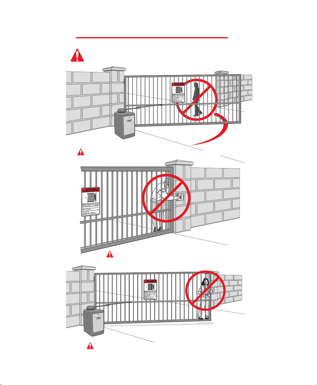
SWING GATE SYSTEMS
• Entrapment Zone Hazard - Body parts may become entrapped between a gate and a sta-
tionary object when the gate begins to move, which can result in serious injury or death.
Pedestrians must stay clear of the gate path, and any area where gate motion is close to
stationary objects.
• Pinch Points Hazard - The opening mechanism may have arms that can overlap with a
scissoring effect, which can result in serious injury. Pedestrians must stay clear of the
opening mechanism at all times, particularly when gate is opening.
3

WARNINGS AND PRECAUTIONS
IMPORTANT!
Instructions regarding
Robo Swing Installation.
A) Install the gate operator only when all exposed pinch points are eliminated
or guarded.
B) The operator is intended for installation only on gates used for vehicles.
Pedestrians must be supplied with a separate access opening.
C) The gate must be installed in a location so that enough clearance is
supplied between the gate and adjacent structures when opening and
closing to reduce the risk of entrapment. Swinging gates shall not open
into public access areas.
D) The gate must be properly installed and work freely in both directions
prior to the installation of the gate operator.
E) Controls must be far enough from the gate so that the user is
prevented from coming in contact with the gate while operating the
controls.
4

WARNINGS AND PRECAUTIONS
F) For a gate operator utilizing a non-contact sensor such as a photo beam:
1) See instructions on the placement of non-contact sensor for
each type of application.
2) Care shall be exercised to reduce the risk of nuisance tripping,
such as when a vehicle trips the sensor while the gate is still
moving.
3) One or more non-contact sensors shall be located where the
risk of entrapment or obstruction exists, such as the perimeter
reachable by a moving gate or barrier.
G) For a gate operator utilizing a contact sensor such as an edge sensor:
1) A hardwired contact sensor shall be located and its wiring arranged
so that the communication between the sensor and the gate operator
is not subjected to mechanical damage.
2) A wireless contact sensor such as the one that transmits radio
frequency (RF) signals to the gate operator for entrapment
protection functions shall be located where the transmission of
the signals are not obstructed or impeded by building structures,
natural landscaping or similar obstruction. A wireless contact sensor
shall function under the intended end-use conditions.
3) One or more contact sensors shall be located on the inside and
outside leading edge of a swing gate. Additionally, if the bottom edge
of a swing gate is greater than 6 inches (152 mm) above the ground at
any point in its arc of travel, one or more contact sensors shall be
located on the bottom edge.
5

WARNINGS AND PRECAUTIONS
IMPORTANT SAFETY INSTRUCTIONS!
WARNING - To reduce the risk of Injury or Death:
1. READ AND FOLLOW ALL INSTRUCTIONS.
2. Never let children operate or play with gate controls. Keep the
remote control away from children.
3. Always keep people and objects away from the gate.
NO ONE SHOULD CROSS THE PATH OF THE MOVING GATE!
4. Test the gate operator monthly. The gate MUST reverse on
contact with a rigid object or stop when an object activates
the non-contact sensors. After adjusting the force or the limit of
travel, retest the gate operator, Failure to adjust and retest the gate
operator properly can increase the risk of injury or death.
4. Use the emergency release only when the gate is not moving. Make
sure the power for the gate operator is off.
5. KEEP GATES PROPERLY MAINTAINED. Read the manual. Have a
qualified service person make repairs to the gate or gate hardware.
6. The entrance is for vehicles only. Pedestrians must use separate
entrance.
7. SAVE THESE INSTRUCTIONS.
6
SAFELY OPERATING GATE
The Robo Swing is for Single Home Applications
DO NOT Use for Apartment or Condominium Applications.
Property owners must never let pedestrians cross the path of a moving gate!
Property owners must never mount any gate
operating device accessible through the gate!
Property owners must never let anyone hang or ride on the gate!
7
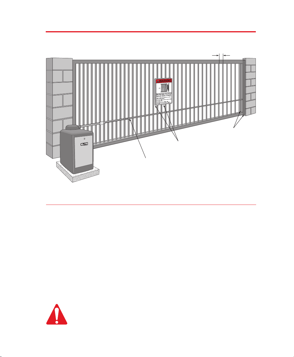
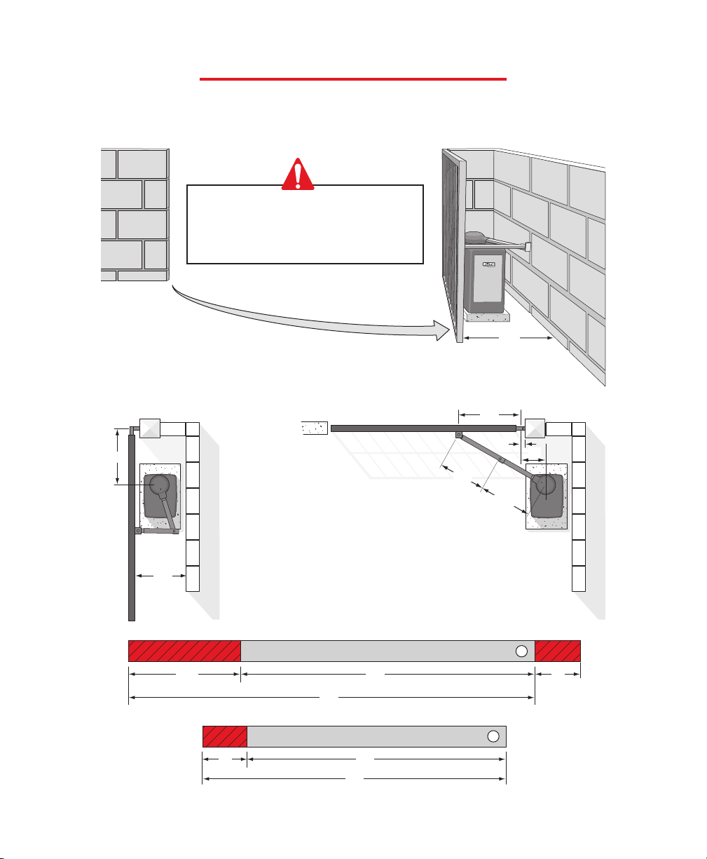
CONFIGURATION AND SPECIFICATIONS
Recommended Gate Setup Configuration
Gate Attachment Bar Must Go Completely
Across the Gate for Full Strength
Warning Placards Permanently
mounted on Both Sides of Gate
4" Max. Width
CAUTION
Robo Swing Specifications:
Gate Speed – 15 - 17 seconds per 90 cycle
Maximum Gate Length – 16 feet
Maximum Gate Weight – 400 pounds
Maximum Cycles – 250 cycles per day with Elite's Plug-In Transformer. (Gate size 16 ft x 6 ft)
– Solar power cycles per day varies, Contact Chamberlain Elite for more
Information
– Battery back-up cycles (50 cycles total)
AC Power Supply – 25 Vdc 1.6 Amp Plug-In Transformer (Part # A POW-1)
AC Power Supply Wire – 14 gauge or greater landscape lighting cable rated for direct burial and
300 watts at maximum length of 1000 ft
DC Power Supply – Built-in, back-up for AC or Solar power failure only
Solar Power – Optional (Part # SOLAR 3)
Be sure to read and follow all Chamberlain Elite's instructions before installing and
operating any Chamberlain Elite product. Always disconnect the gate operator's
power source before repairs are attempted. Chamberlain Elite Access Systems, Inc. is
not responsible for improper installation or failure to comply with local building
codes.
All “Pinch Points” MUST have protective safety devices.
Edge Sensors
8
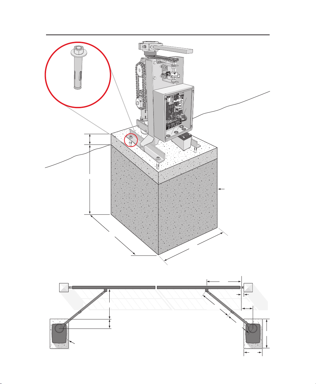
CONCRETE PAD AND GATE ATTACHMENT
6"
Out
In
Post
Concrete Pad
Concrete Pad
Above
Ground
Below
Ground
Short Arm
Long Arm
Hinge
Center
14"
2"
24"
35.5"
46"
28"
25"
10"
29.5"
30"
28"
24"
Concrete Fastener
1/2" x 3 1/2"
Sample Standard Installation
J2
1.5A - 250V
1.5A - 250V
9
STANDARD INSTALLATION
D
10"
Out
Long Arm
In
Out
In
*Refer to Note
Concrete Pad
Hinge Center
E
B
A
C
Sample Standard Installation is Shown on Previous Page.
Short Arm
DistanceDistance
Caution: If the gate is longer than 18 feet, follow Chart A : A-2.
Suggestion: The dimension between the gate and the concrete pad is always 10 inches less than the dimension D.
Example: D = 42", if the dimension between the gate and the concrete pad is 32".
1
2
3
4
5
6
34.5"
44"
44"
45"
44.75"
41"
34.75"
36.5"
37"
37"
35.75"
39"
29.5"
32.5"
30.5"
30.5"
29.5"
27.5"
35"
42"
40"
37"
32"
28.5"
14"
14"
14"
14"
14"
14"
43"
32"
40"
43"
44"
41"
ABC
Chart B
DE
DistanceDistance
1
2
3
4
5
6
46"
46.75"
46.75"
47.25"
47"
42.5"
35.5"
35.5"
37"
37.25"
35"
33"
29.5"
33.5"
31.5"
30"
29.5"
26.5"
35"
42"
40"
37"
32"
28.5"
11"
11"
11"
11"
11"
11"
45"
37"
41"
45"
45"
41"
ABC
Chart A
DE
DistanceDistance
D minus 10"
*Note - If this dimension is between 20 and 32 inches, compact installation is necessary. (Refer to Page 11)
Dimension (A) thru (E) are from the center of one pivot point
to the center of another pivot point.
Wall
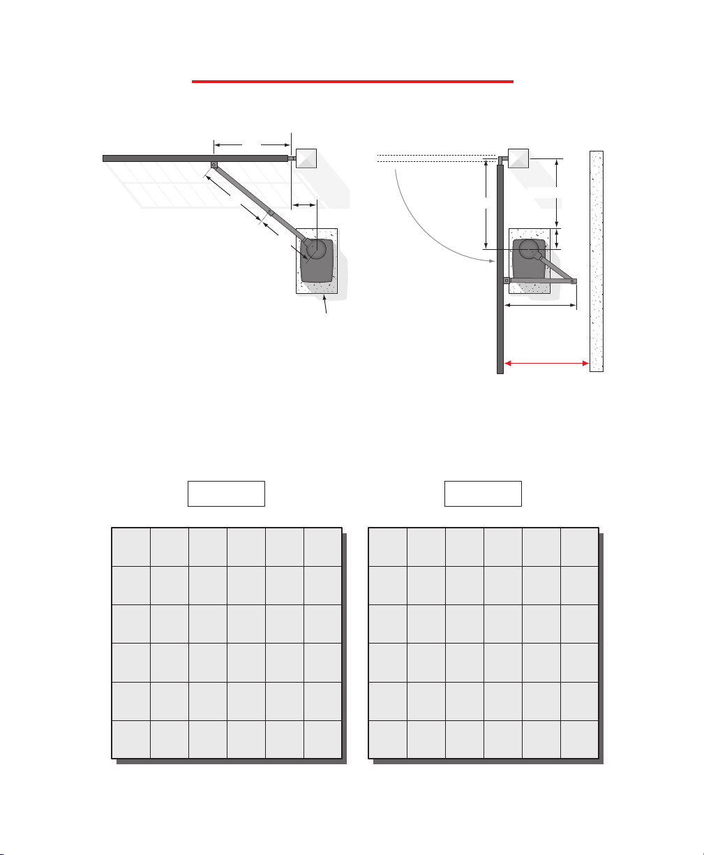
10
20"
Minimum
Width
COMPACT INSTALLATION
4"22"
4" 20"
24"
36"
10"
Long Arm
Cut Cut
Short Arm
Cut
Follow the exact measurements, then cut the standard arm to meet the shorter measurements.
Compact Installation Only!
DO NOT Use These Measurements for a Standard Installation.
Gate ClosedGate Open
Hinge Center
9"
2"
33"
25.5"
23"
20"
to
32"
26.5"
It is necessary to protect against the
entrapment that could occur with this
type of installation.
(See page 22, Photo Beam Entrapment Protection)
11
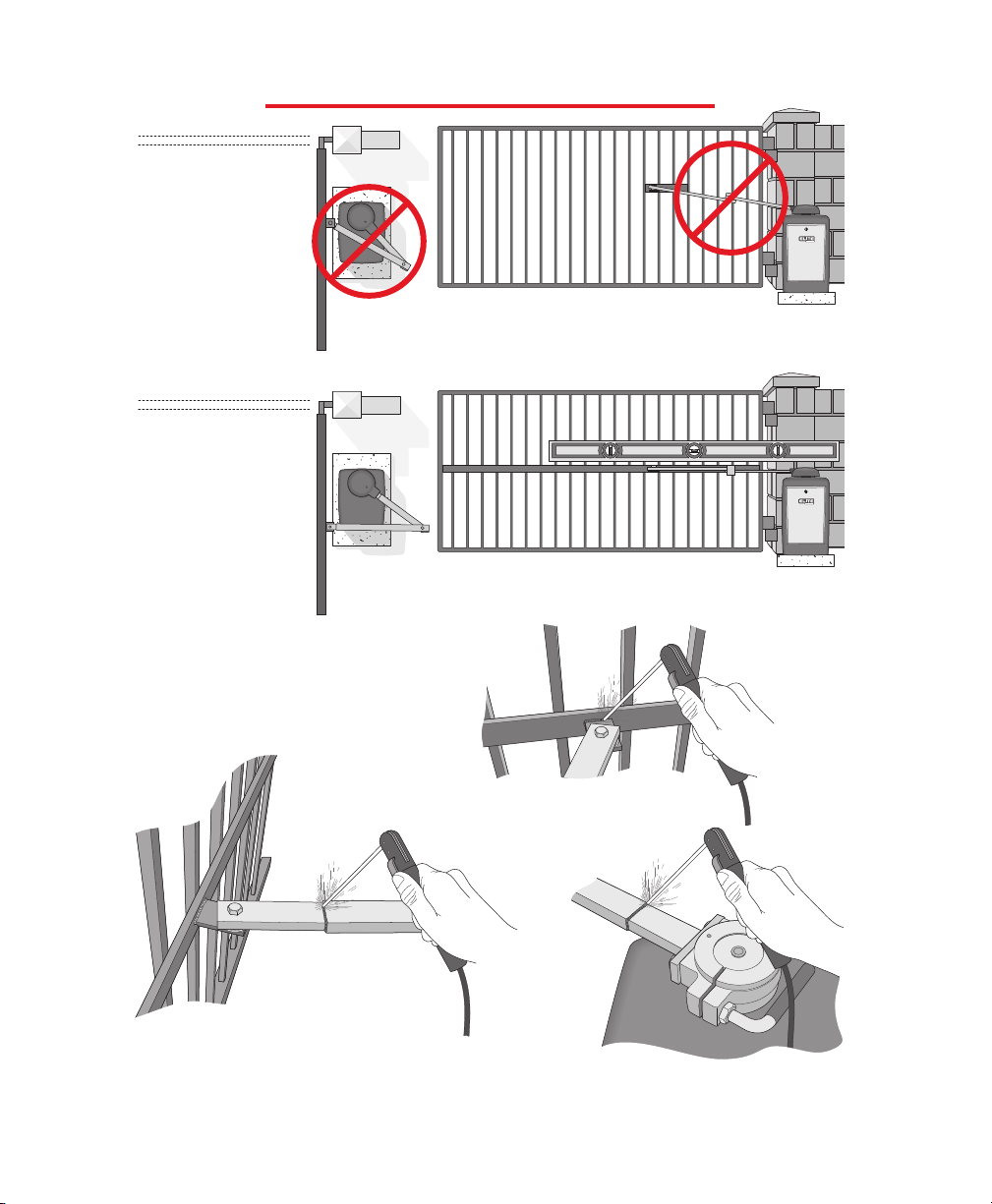
GATE ARM INSTALLATION
Incorrect
Installation
Correct
Installation
Weld Completely Around the Rectangular Tubes
........then weld the shorter arm.
Weld the longer arm..........
Once the gate arm measurements are calculated:
weld the bracket on the gate.
12
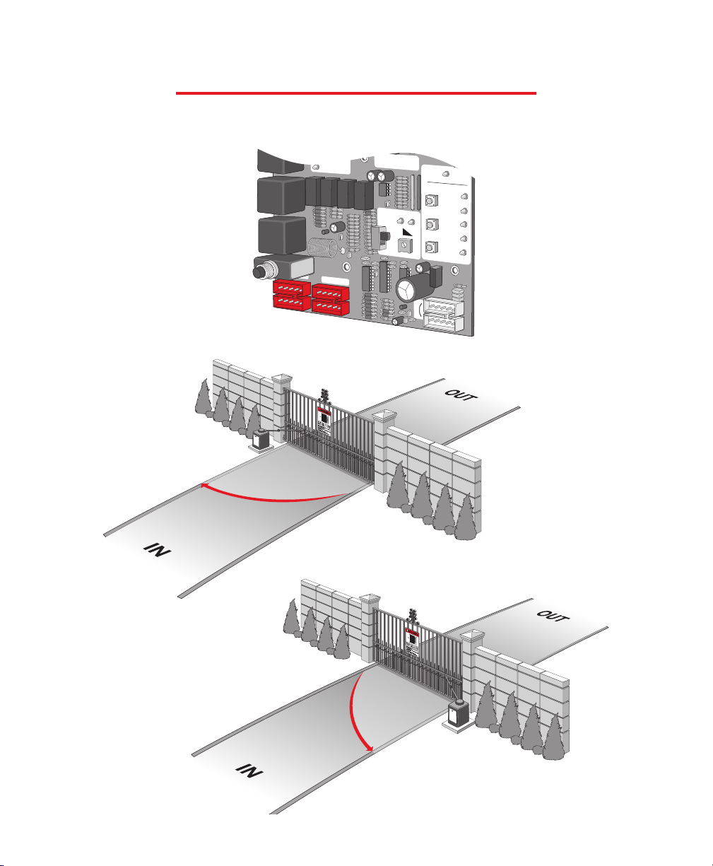
OVERLOAD
POWER
CHARGE OK
BATTERY LOW
OPEN RELAY
CLOSE RELAY
TIMER
UP
ON
W1
OFF
OPEN TO RIGHT
Socket 1
Socket 2
60
0
PW
CENTRAL CONTROL
SYSTEM ON
DC OPERATOR v 5M
MADE IN USA
ALARM
SENSOR
REVERSE
SENSOR
HEAVY
GATE
FIRE
DEPT
STRIKE
OPEN
SAFETY
LOOP
EXIT
LOOP
RADIO
REC
CHARGING
POWER
BOARD
POWER
CHECK
FUSE
J2
OPEN
CLOSE
STOP
GATE MOVEMENT DIRECTION
Plug in the motor harness wires to the left (Socket 1) if your gate, from the inside of the
property, opens to the left. Plug into the right (Socket 2) if the gate opens to the right.
Socket 1
Open to Left
Open to Right
Socket 2
13
 Loading...