

Page 1
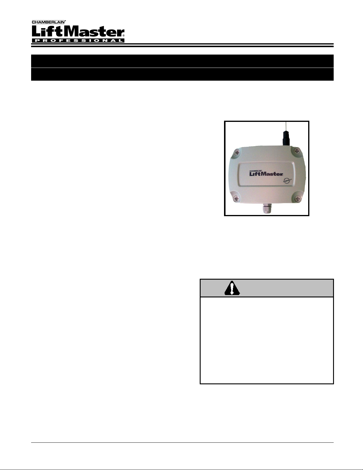
Wiegand Receiver with Passport Technology
Installation and Operation Instructions
SPECIFICATIONS
Power: 12VDC, 50 mA
Temperature Rating: -40º to +185º F
RF Frequency: 390 MHZ
Accessory Transmitters
Visors: CPT1, CPT2, CPT3, CPT4
Keychains: CPTK1, CPTK3, CPTK1PH, CPTK3PH
TABLE OF CONTENTS
SETTING THE SWITCHES .................................................... 2
INSTALLATION AND WIRING ...............................................4
TESTING AND TROUBLESHOOTING ..................................5
APPENDIX: FACILITY CODE SWITCH SETTINGS .............. 6
OVERVIEW
The Wiegand Receiver (CPWR) is a communication
device that transmits an information packet to an access
control unit such as a Sentex Telephone Entry System.
All receiver units utilize the latest in Chamberlain® rolling
code technology.
ACCESS CONTROL COMPATIBILITY
The CPWR outputs a 26-bit or 30-bit Wiegand format
compatible with Sentex access control systems.
Doc 6001535, Rev G
Page 1 of 6
WARNING
Children operating or playing with a garage
door/gate opener can injure themselves
and others. The door/gate could close and
cause serious injury or death. Do not allow
children to operate the door control push
button or the remote control transmitters.
Install the receiver (and all control push
buttons) out of the reach of children and
away from all moving parts of the door/gate
hardware, but where the door/gate is
visible.
Page 2

Setting the Switches
Before making changes to any of the DIP switches, power MUST be disconnected from the receiver
(unplug the terminal block from J2 on the circuit board). Otherwise, your changes will not take effect.
Also, when setting the receiver’s DIP switches, refer only to the numbers silk screened on the PC board
(not the numbers on the DIP switch itself).
FACILITY CODE
15
14
13
12
11
10
9
8
73
6
5
4
3
2
1
0
FORMAT
2
1
0
3
2
1
BUTTON
FFC
1535F3
Figure 1: DIP Switch Location
STEP 1: REMOVE FRONT COVER
Turn screws counterclockwise 1/4 turn and remove front cover.
STEP 2: DISCHARGE STATIC
Before or while touching the circuit board, discharge any static electricity:
(1) Use a grounding strap OR
(2) Touch a cold, grounded, metallic pipe.
STEP 3: OUTPUT CODE FORMAT
The output code format switch settings are factory-set
for the 30-bit format (see Figure 2). To change the
settings to 26-bit, refer to Figure 3.
30-bit Switch Settings (Default):
S1, 3 = OFF or 0
S1, 2 = OFF or 0
S1, 1 = ON or 1
S1, 0 = ON or 1
26-bit Switch Settings:
S1, 3 = OFF or 0
S1, 2 = OFF or 0
S1, 1 = ON or 1
S1, 0 = OFF or 0
Left = OFF or 0
Right = ON or 1
Doc 6001535, Rev G
Page 2 of 6
Figure 2: 30-bit DIP Switch Setting
Figure 3: 26-bit DIP Switch Setting
1535F7
1535F10
S1
S1
FORMAT
FORMAT
3
2
1
0
3
2
1
3
2
1
0
3
2
1
BUTTON
FFC
BUTTON
FFC
Page 3

STEP 4: SET THE TRANSMITTER BUTTON RESPONSE(S)
There are three DIP switches used to set the
transmitter button response(s). See Figure 4
or Figure 5.
To disallow receiver response to transmitter
buttons, move the DIP switch(es) to the LEFT.
All button switches are factory set to ON.
Switch S1, 1 controls Button #1 and
Button #4*
Switch S1, 2 controls Button #2
Switch S1, 3 controls Button #3
* If using a CPT4 transmitter, Button #4 reacts
to Button #1 settings, but uses a unique
identification number and facility code.
Figure 4: CPT4 Transmitter Button Switches
CPT4
Transmitter
1535F8
S1
FORMAT
2
0
2
Buttons 1-3 are
factory-set to ON.
S1
FORMAT
3
2
1
0
3
2
1
3
1
3
1
FFC
FFC
BUTTON
BUTTON
SETTING A FIXED FACILITY CODE (FFC)
1 The FFC switch must be in the ON
position (switch set to right).
2 Set the receiver’s facility code switches
(labeled 0-5) to match the facility code of
the access control system.
Refer to the switch settings chart in the
Appendix on page 6 for assistance.
NOTE: For installations that require the
facility code of the transmitters to be
passed to the access control system,
set the FFC switch to the OFF position
(set switch to left). Facility codes are
set in the transmitter at the factory to
avoid code duplication.
Buttons 1-3 are
factory-set to ON.
3
1
2
3-Button Remote
Tra nsmitter
1535F11
Figure 5: 3-Button Transmitter Button Switches
Facility code switches
6-15 are not used (must remain in the OFF or left position).
FFC Factory Setting = ON (switch set to right).
Facility Code Factory Setting = All OFF (switches set to left).
FACILITY CODE
15
14
13
12
11
10
9
8
73
6
5
4
3
2
1
0
Figure 6: Facility Code Switches
FORMAT
2
1
0
3
2
1
1535F9
BUTTON
FFC
Doc 6001535, Rev G
Page 3 of 6
Page 4

Installation and Wiring
PARTS SUPPLIED
Wiegand Receiver
Antenna
Installation and Operation Instructions
STEP 1: MOUNT THE RECEIVER
Mount receiver to surface using #6 hardware (not
supplied). Refer to Figure 8 for receiver mounting
hole locations.
NOTE: Mount receiver with 18” of space above
the receiver for the antenna. Also, receivers
should be installed at least 5 feet apart to
avoid “cross-talk”.
STEP 2: CONNECT THE ANTENNA
Screw on antenna clockwise and slide rubber boot
down to meet o-ring (see Figure 7).
CAUTION
PARTS NOT SUPPLIED
# 6 Mounting Hardware
5-conductor shielded cable; 22 AWG wire
Extension Kit (Optional)
The outside of the antenna connector is not
ground. If using an extension kit, do not allow it
to contact a metal object.
STEP 3: CONNECT SIGNAL/POWER WIRES
Remove the terminal block from J2 on the circuit
board. Connect wires from the CPWR 6-pin
connector to the access control system. Refer to
Figure 8. Then re-insert the terminal block onto J2.
Wire the CPWR to the access control systems’
card reader port. Refer to the access control
system’s installation instructions for appropriate
wiring detail. A typical wire connection might
resemble the following:
CABLE SIGNALS WIRE COLOR
LED BROWN
DATA 1 WHITE
DATA 0 GREEN
+12VDC RED
COMMON (GND) BLACK
SHIELD SHIELD
NOTE: At power up, the CPWR will perform a
system check and produce a series of LED
flash sequences. This is normal.
1535F5
Figure 7: Antenna Attachment
Mounting Holes
(4 Corners)
J2
1535F4
To Access Control
Circuit Board (Reader Port)
Figure 8: Signal and Power Connections
Doc 6001535, Rev G
Page 4 of 6
Page 5

Testing and Troubleshooting
STEP 1: CHECK THE POWER
Ensure that the red POWER LED is lit (see Figure 9). If
not, check your power connections and/or source. Voltage
reading should be within the range of 9VDC – 18VDC.
STEP 2: CHECK FOR RECEIVER OPERATION
The SIGNAL LED (refer to Figure 9) should be flickering
continuously, indicating that the RF receiver circuitry is
operating.
STEP 3: TEST THE TRANSMITTER/RECEIVER
Press the transmitter button previously set in step 4, page
3, within view of the receiver. If the DATA-yellow and
VALID-green LEDs do not light, review the Setting the
Switches and Connect Signal/Power Wires sections.
If reception of the transmitter’s signal is significantly
reduced, there may be strong RF interference from other
sources. Common sources of interference include
fluorescent lights, neon signs, mercury vapor lamps, arc
welders, and arcing power lines. Interference due to
lighting can be limited by having an electrician wire a
noise suppressor into the lamp, light, or sign circuit.
If the DATA-yellow and VALID-green LEDs
flash repeatedly and simultaneously, the
format settings may be incorrect (refer to
Output Code Format).
WARNING
Call your local power company if
interference is due to arcing power
NOTE: It may be required to press the transmitter
button twice at first use.
RECEIVER LED REFERENCE
(Refer to Figure 9.)
SIGNAL – Red
This LED, when lit, indicates that the receiver has
detected the presence of RF energy. It is normal for this
LED to flicker continuously while the receiver is powered
up.
DATA – Yellow
This LED indicates that the receiver recognizes the
transmission data as coming from a Chamberlain®
transmitter with Passport technology.
VALID – Green
This LED indicates that the receiver is sending a
Wiegand format output to the access control system.
POWER – Red
This LED indicates that the receiver has power.
GRANTED – Green
This LED indicates that the access control system has
validated the transmitted code and has granted access.
STEP 4: ATTACH THE FRONT COVER
Attach front cover of receiver by turning screws clockwise
1/4 turn. Do not overtighten.
1535F6
D11
SIGNAL
D12
DATA
D13
VAL I D
D9
POWER
D1
GRANTED
Figure 9: Location of LEDs
Doc 6001535, Rev G
Page 5 of 6
Page 6

Appendix: Facility Code Switch Settings
Refer to Figure 1 on page 2 for the facility code DIP switch location. Also, when setting the receiver’s
DIP switches, refer only to the numbers silk screened on the PC board (not the numbers on the DIP
switch itself).
FC 000 001 002 003 004 005 006 007 008 009 010 011 012 013 014 015 016 017 018 019
5
0 0
4
0 0
3
0 0
2
0 0
1
0 0
0
0
FC 020 021 022 023 024 025 026 027 028 029 030 031 032 033 034 035 036 037 038 039
5
0 0
4 1
3
0 0
2 1
1
0 0
0
0
FC 040 041 042 043 044 045 046 047 048 049 050 051 052 053 054 055 056 057 058 059
5 1
4
0 0
3 1
2
0 0
1
0 0
0
0
FC 060 061 062 063
5 1
4 1
3 1
2 1
1
0 0
0
0
LIMITED WARRANTY
LiftMaster warranties the receiver against original manufacturing defects for a period of three (3) years, measured from the day
of initial shipment by LiftMaster. This warranty is conditioned upon LiftMaster being paid in full for all equipment; this warranty
is not effective until such payment in full has been received. The warranty period shown above applies only to the LiftMaster
receiver with Passport technology). Since this is a manufacturer's warranty, not a dealer's warranty, installation, removal, and
freight charges are not part of this warranty, nor shall the installer be held liable in any way for removal, repair or installation of
the Passport system unless otherwise stated in a separate dealer's warranty. This warranty does not extend to systems or
compartments that show evidence of damage caused by vandalism, acts of God (e.g., lightning, flood), abuse, or unauthorized
or improper service.
0 0 0 0
0 0 0 0
0 0 0 0
0 0
1 1
1
0
0 0 0 0
1
1 1 1 1
0 0
1
1 1
1 1
1
0
1
1 1 1 1
0 0 0 0
1
1 1 1 1
0 0
1 1
1
0
1
1 1
1
1 1
1
1 1
1
1 1
1 1
1
0
0 0
0 0
0 0
1 1
0 0
1
0
1 1
0 0
0 0
1
0
1 1
0 0
1
0
1 1
1 1
1
0
0 0
1 1
1 1
0 0
1 1
1
0
1 1
0 0
1 1
1 1
1 1
1
0
0
1
1
1
0 0
0
0 0
1
1 1
0
0 0
0
0
1
0
0
0 0
1
1 1
1
1 1
1
1 1
0
0
1
0
1
1 1
1
1 1
0
0 0
0
0 0
0
0
1
0
0 0 0 0 0
0 0 0 0 0
1 1 1 1 1
1
0
1
0
1
0
1 1 1 1
0
1
0 0
1
0
1 1 1 1
0
1
0 0 0 0
1
0 0 0 0
1
0 0 0 0
1
0 0
1
0
1 1 1 1 1
1 1 1 1 1
0 0 0 0 0
1 1 1 1
0
1
0 0
1
0
0
1
0
0
0
0
1
0
0
1
0
0
1
1
1
0
0
0
0 0 0
1 1 1
0 0 0
0 0 0
1 1
0
1
0
1 1 1
0 0 0
0 0 0
1 1 1
1 1
0
1
0
1 1 1
1 1 1
1 1 1
0 0 0
1 1
0
1
0
1
1
1
1 1
1
1
0
1 1
1
1
0
1 1
1
1
0
FCC REQUIREMENTS
This device complies with FCC Rules Part 15 and IC Canada Rules and Regulations.
Operation is subject to the following two conditions: (1) This device may not cause harmful
interference and (2) this device must accept any interference received, including interference
that may cause undesired operation. FCC rules prohibit adjustments to or modification of
1
receiver and/or remote control transmitter circuitry except for changing the code setting and
replacing the remote control transmitter battery.
There are no other serviceable parts.
COPYRIGHT 2001, ALL RIGHTS RESERVED
This document is protected by copyright and may not be copied or adapted without the prior written consent of LiftMaster. This
documentation contains information proprietary to LiftMaster and such information may not be distributed without the prior
written consent of LiftMaster. The software and firmware included in the LiftMaster product as they relate to this documentation
are also protected by copyright and contain information proprietary to LiftMaster.
FOR TECHNICAL SUPPORT
OR TO ORDER REPLACEMENT PARTS
Call our toll free number: (800) 528-2806
Prepare to provide the following information when ordering parts:
Part Number
Part Name
Model Number
Manufacturer’s Date
Installation and service information
is available six days a week (Monday-Saturday).
Doc 6001535, Rev G
Page 6 of 6
 Loading...