

Liftmaster MGJ User Manual
OWNER'S MANUAL
LISTED DOOR OPERATOR
41B6
MODEL
MGJ (S-Series)
INDUSTRIAL DUTY DOOR OPERATOR
FOR USE WITH SS90 FIRE DOOR CONTROLLER
2 YEAR WARRANTY
Serial #
(located on electrical box cover)
Installation Date
Wiring Type
NOT FOR RESIDENTIAL USE

Before attempting to install, operate or maintain the operator, you must read and fully understand this
manual and follow all safety instructions.
These instructions are intended to highlight certain safety related issues. These instructions are
not intended to be comprehensive. Because each application is unique, it is the responsibility of
the purchaser, designer, installer and end user to ensure that the total door system is safe for its
intended use.
TABLE OF CONTENTS
OPERATOR SPECIFICATIONS
Hardware Packing List . . . . . . . . . . . . . . . . . . . . .2
Operator Specifications . . . . . . . . . . . . . . . . . . . .3
Operator Dimensions . . . . . . . . . . . . . . . . . . . . . .3
Safety Notes . . . . . . . . . . . . . . . . . . . . . . . . . . . . .4
Site Preparation . . . . . . . . . . . . . . . . . . . . . . . . . .4
Handing Preparation . . . . . . . . . . . . . . . . . . . . . . .4
Operator Mounting
Entrapment Protection . . . . . . . . . . . . . . . . . . . . .7
Limit Adjustment . . . . . . . . . . . . . . . . . . . . . . . . . .7
Maintenance Schedule . . . . . . . . . . . . . . . . . . . . .8
. . . . . . . . . . . . . . . . . . . . . . . . . .5 & 6
Control Wiring . . . . . . . . . . . . . . . . . . . . . . . . . . . .
Single Phase Wiring Diagram . . . . . . . . . . . . . . . .10
Three Phase Wiring Diagram . . . . . . . . . . . . . . . .11
Replacement Parts Electrical Box . . . . . . . . . . . . .12
Electrical Box Diagram . . . . . . . . . . . . . . . . . . . . .13
Replacement Parts Frame . . . . . . . . . . . . . . . . . .14
Frame Diagram . . . . . . . . . . . . . . . . . . . . . . . . . .15
Control Connections . . . . . . . . . . . . . . . . . . . . . . .16
9
HARDWARE PACKING LIST
Before beginning your installation check that all components were supplied and received undamaged. Refer to list below
for Factor y Supplied par ts.
HARDWARE KIT MGJ SSSI (K77-18599)
PAR T #
01-18600
02-103-R
10-10463
19-41119MB
77-13709
OWNERS MANUAL, MGJ SSSI
REWORK, PBS, RED PAINT
KEY HOLE BRACKET
CHAIN #41X119 W/ MASTER
LABEL KIT MED DUTY
DESCRIPTION
2
QTY.
1
1
1
1
1

SPECIFICATIONS
MOTOR
TYPE: .................................Intermittent Duty
HORSEPOWER:.................1/2Hp 1 or 3 Phase
SPEED:...............................1050 RPM
VOLTAGE: ..........................115, 60HZ, 1Ph
230V, 60Hz, 3Ph
CURRENT: See motor nameplate
MECHANICAL
DRIVE REDUCTION:.... . . . . . . . . . . 40:1 Reduction
(Heavy duty wormgear-in-oil-bath speed reducer)
OUTPUT SPROCKET:..........Size #41
DOOR SPEED:. . . . . . . . . 1Ph, 23RPM
3Ph, 39RPM
BEARINGS: Heavy duty wormgear-in-oil-bath
speed reducer.
ELECTRICAL
TRANSFORMER:.............24VAC
CONTROL STATION: ......NEMA 1 three button station.
WIRING TYPE:.................B2-C2 (Factory Shipped)
LIMIT ADJUST: ................Linear driven, fully adjustable
screw type cams. Adjustable to 24 feet.
OPEN/CLOSE/STOP
SAFETY
DISCONNECT :.......................Floor level disconnect for
emergency manual door operation.
REVERSING EDGE:...............(Optional) Electric
A REVERSING EDGE IS STRONGLY RECOMMENDED
ALL
FOR
REQUIRED
IS OUT OF SIGHT OF DOOR OR ANY OTHER CONTROL (AUTOMATIC OR MANUAL) IS USED.
COMMERCIAL OPERATOR INSTALLA TIONS.
WHEN THE 3 BUTTON CONTROL STATION
MGJ WEIGHTS AND DIMENSIONS
HANGING WEIGHT: .........80-110 LBS.
7.50”
11.05”
7.00”
9.25”
10.50”
11.00”
3
3.00”
MOUNTING DIMENSIONS
5.50”
4.75”

WARNING
CAUTION
WARNING
WARNING
WARNING
IMPORTANT SAFETY NOTES
CAUTION
TO AVOID DAMAGE TO DOOR AND OPERATOR,
MAKE ALL DOOR LOCKS INOPERATIVE. SECURE
LOCK(S) IN "OPEN" POSITION.
IF THE DOOR LOCK NEEDS TO REMAIN FUNCTIONAL, INSTALL AN INTERLOCK SWITCH.
DO NOT CONNECT ELECTRIC POWER UNTIL
INSTRUCTED TO DO SO.
SITE PREPARATIONS
It is imperative that the wall or mounting surface provide
adequate support for the operator.
This surface must:
a) Be rigid to prevent play between operator and
door shaft.
b) Provide a level base.
c) Permit the operator to be fastened securely and
with the drive shaft parallel to the door shaft.
The safety and wear of the operator will be adversely
affected if any of the above requirements are not met.
For metal buildings, fasten 2” x 2” x 3/16” (or larger) angle
iron frames to the building purlins. For proper spacing,
retain .2.75” between. See Figure 1.
WARNING
KEEP DOOR BALANCED. STICKING OR BINDING
DOORS MUST BE REPAIRED. DOORS, DOOR
SPRINGS, CABLES, PULLEYS, BRACKETS AND
THEIR HARDWARE MAY BE UNDER EXTREME TENSION AND CAN CAUSE SERIOUS PERSONAL
INJURY. CALL A PROFESSIONAL DOOR SERVICEMAN TO MOVE OR ADJUST DOOR SPRINGS OR
HARDWARE.
Shaft Support Bracket
with Bearing (Not Supplied)
Door Sprocket
2-1/4"
2.75
FIGURE 1
OPPOSITE HANDING PREPARATIONS
Shipped from the factory for either left hand or right hand mounting.Refer to next to last digit in the model number for handing of your unit. If necessar y, model MGJ may also be field modified to accommodate opposite handing. Refer to the conversion instructions below and on page 5.
1. Remove Disconnect Assembly Components
Remove the master link from the limit chain, remove the
chain and set it aside.
KEYS
SPRING
DISCONNECT
HUB
SPROCKET
E RING
SHAFT
BRACKET
YOKE
Remove the two E Rings securing the sprocket on the
gear reducer shaft. Remove the screws securing the yoke
to the disconnect shaft, set the yoke aside.
DISCONNECT
LEVER
4
Remove the three cotter pins from the disconnect shaft.
Do not discard the pins. Slide the disconnect shaft out of
the support bracket. The release lever will now be free
inside the motor frame. Remove the release lever and
sash chain from the motor frame. Slide the disconnect
hub, compression spring, and flatwasher from the end of
the gear reducer shaft. Remove the disconnect support
bracket by first removing the the two gear reducer housing screws. Replace the screws in the gear reducer and
firmly tighten.
2. Re-assemble Disconnect Assembly
Remove the two screws on the opposite side of the gear
reducer and mount the disconnect support bracket with
the notched side facing the motor. For the remainder of
the installation, follow the steps outlined above in reverse
order, referring to the illustration as necessary.
OPERATOR MOUNTING
Before your operator is installed, be sure the door has been properly aligned and is working smoothly. The operator may
be wall mounted or mounted on a bracket or shelf. If necessary, refer to the operator preparations on page 3. Refer to the
illustration and instructions below that suits your application.
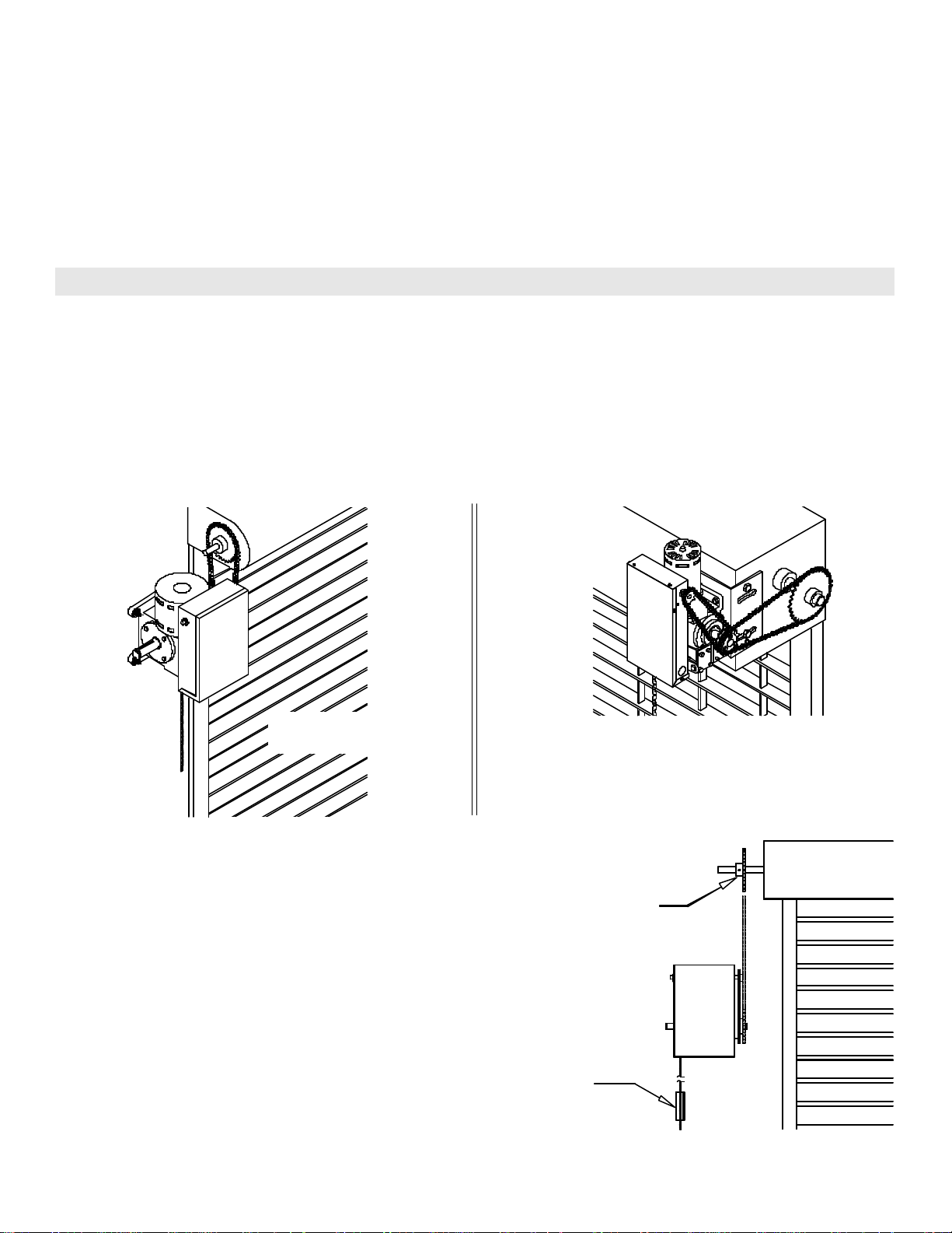
1a.Wall Mounting
The operator should generally be installed below the door
shaft, and as close to the door as possible. The optimum
distance between the door shaft and operator drive shaft is
between 12” - 15”.Refer to Figure 3.
FIGURE 3
Typical Left Hand
Wall Mounted Operator
1b.Bracket or Shelf Mounting
The operator may be mounted either above or below the
door shaft. The optimum distance between the door shaft
and operator drive shaft is between 12” - 15”. Refer to
Figure 4.
FIGURE 4
IMPORTANT:The shelf or bracket must provide adequate
support, prevent play between operator and door shaft,
and permit operator to be fastened securely and with the
drive shaft parallel to the door shaft.
FIGURE 5
1c.Place door sprocket on the door shaft. Do not insert the
key at this time.
2. Wrap drive chain around door sprocket and join roller
chain ends together with master link.
3. Raise operator to approximate mounting position and
position chain over operator sprocket.
4. Raise or lower operator until the chain is slightly taut
(not tight). Make sure the operator output shaft is parallel to door shaft and sprockets are aligned. When in
position, secure the operator to wall or mounting bracket.
5. Align sprockets and secure, (see Figure 5).
Be sure door
sprocket is properly
aligned with drive
before securing to
the shaft.
Chain Keeper
5
 Loading...