

Page 1
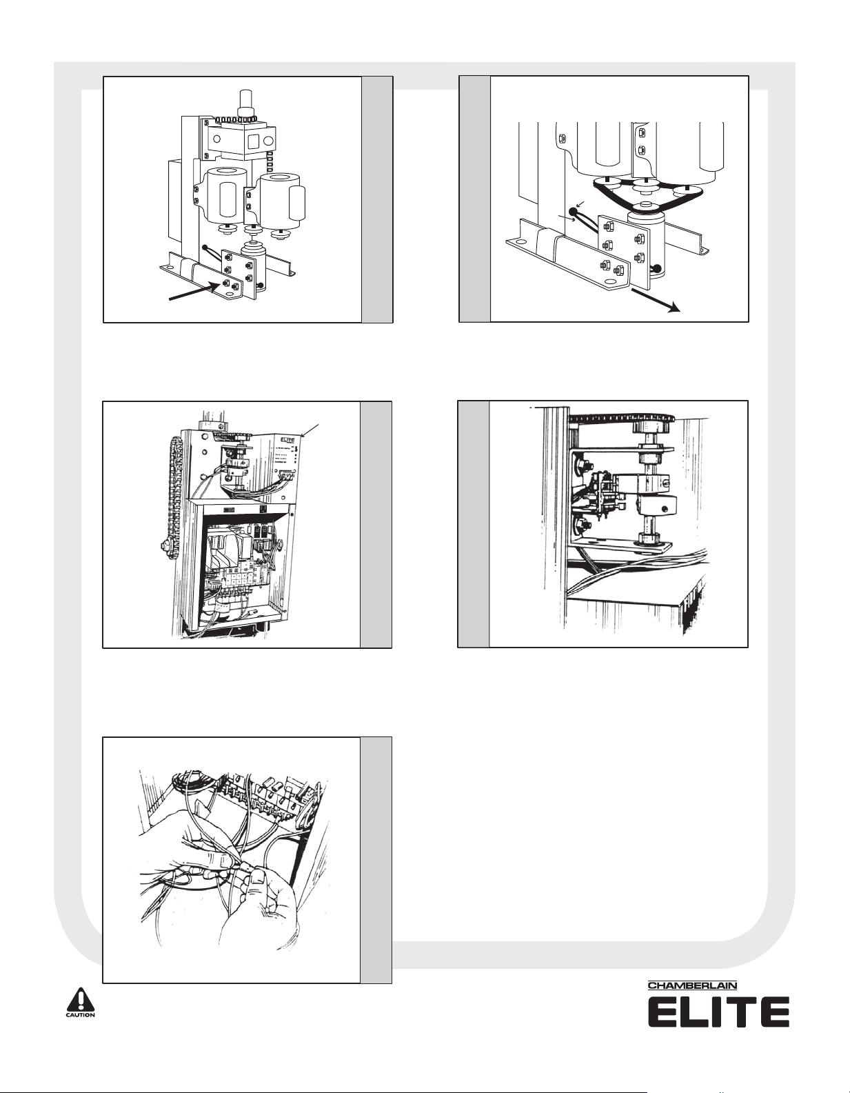
Installation for the DC1000U™ CSW200ULDM™
STEP 1
Bolt On
Remove existing belt and mount plate and new motor onto
chassis, DO NOT fully tighten bolts.
DC1000U™
STEP 3 STEP 5
STEP 2
Hole
Wires
Pull Motor
to Tighten
Belt
Put new belt in place around pulleys.
are in line.
tightening bolts. Put 2 wires from new motor through
appropriate hole in chassis as shown.
Pull motor to tighten belt, then finish
Make sure pulleys
STEP 4
Place DC1000U™ unit on top of main control box and
install 2 wires from in back of DC1000U™ to 2 wires from
12V motor, using wire nuts provided.
change the direction the DC1000U™ will open.
CAUTION:
Connect the HOT wire from the power source to the BLACK
wire from the DC1000U™ plug, Then the BLUE wire from
the DC1000U™ plug to the BLACK wire on the operator.
See diagram on back of this sheet.
DO NOT connect 120 Vac to DC1000U™.
Crossing wires will
Mount new limit switches on top of existing limit switches.
Wire new limit switches to DC1000U™ plug using wiring
diagram on back of this sheet.
For Technical Support: 1-800-528-2806
®
™
© 2004 The Chamberlain Group, Inc.
All Rights Reserved
Page 2
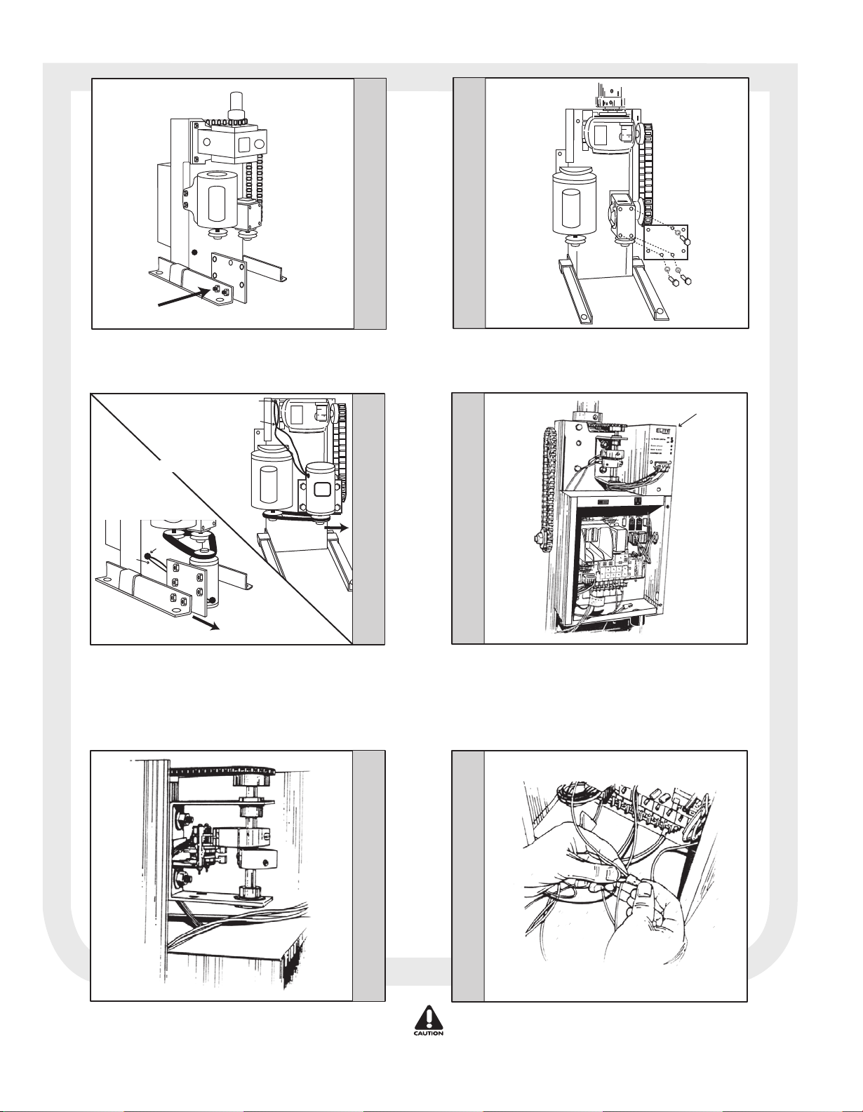
Installation for the DC1000U™ CSW200UL™
STEP 1-A
Bolt On
Remove existing belt. Mount new plate on chassis. Bolt in
place (as shown) with bolts provided.
Hole
Wires
1-B
Configuration
OR
1-A
Configuration
Hole
Wires
Pull Motor
to Tighten
Belt
STEP 2
STEP 1-B
OR
Remove existing belt. Mount new plate on lower gearbox.
Bolt in place (as shown) with bolts provided.
DC1000U™
STEP 3 STEP 5
01-50586
Pull Motor
to Tighten
Belt
Bolt DC motor to plate of Step 1A OR 1B. Put new belt in
place around pulleys.
motor to tighten belt, Then finish tightening bolts. Put 2
wires from new motor through appropriate hole in chassis
as shown.
Make sure pulleys are in line.
Pull
STEP 4
Mount new limit switches on top of existing limit switches.
Wire new limit switches to DC1000U™ plug using wiring
diagram on back of this sheet.
Place DC1000U™ unit on top of main control box and
install 2 wires from in back of DC1000U™ to 2 wires from
12V motor, using wire nuts provided.
change the direction the DC1000U™ will open.
CAUTION:
Connect the HOT wire from the power source to the BLACK
wire from the DC1000U™ plug, Then the BLUE wire from
the DC1000U™ plug to the BLACK wire on the operator.
See diagram on back of this sheet.
DO NOT connect 120 Vac to DC1000U™.
Crossing wires will
Page 3

Wiring the DC1000U™ to a:
Main Style Commercial Board
Wiring the DC1000U™ to a:
OmniControl™ Board
ON
OFF
Wiring the DC1000U™ to a:
OmniControl™ Board with Surge Suppressor
ON
OFF
Wiring Optional Equipment
to the DC1000U™
All devices wired to the DC1000U™ are dedicated to it
alone. Normal operation will be controlled by separate
devices wired to the operator control board.
J-1 Plug
46810
Black Wire
J-1 Plug
Pin 4
J-1 Plug
J-1 Plug
Close Buttons, Key Switches, Etc.
2
46810
T
XI
E
Y
T
FE
SA
R
E
T
N
E
2
13579
765432189
10
Fire Dep
Key Switch
Strike Open or
Push Button
Or Photocell
Exit LoopSafety Loop
-
Radio Receiver
+
C
To B lue Wire
To Black Wire
4
W
GB
S
M
A
NK
I
L
T
I
YEX
T
E
F
A
S
ER
NT
E
C
13579
Cut Black
Wire
SYSTE
S
E
M
R
A
L
A
RM
A
L
A
R
O
P
KU
C
A
C-B
D
S
N
E
S
M
O
N
T
IME
S
N
O
R
S
R
O
1
3
ENS
S
D
D
E
N
S
A
S
E
M
C
M
O
RO
C
P
R
E
S
O
FF
OR
R
S
E
N
V
1
3
E
E
S
R
O
P
E
N
L
E
F
T
F
I
R
E
S
T
R
I
K
E
R
A
D
O
D
E
P
E
X
L
O
O
I
T
.
O
P
E
N
R
E
C
E
IV
E
R
T
I
S
A
E
F
T
Y
C
E
N
T
E
R
P
L
O
O
P
L
O
O
P
P
OW
E
60
1
ON
O
P
E
L
M
R
3
O
VER
L
O
A
D
3
N
E
M
A
D
E
I
N
U
S
A
OP
N
R
G
I
H
T
P
O
T
S
G
A
T
E
O
C
K
E
D
OSE
R
E
E
S
T
CL
O
T
O
R
To B lue Wire
To Black Wire
ER S
T
N
E
C
4
W
A
B
G
K
N
LI
S
M
T
I
X
E
Y
T
E
AF
S
R
E
T
CEN
CHASSIS
GROUND
To Terminal Block
8 and 10
To Terminal Block
8 and 10
Blue
46810
T
I
EX
Y
ET
F
A
Cut Black
Wire
GG
BB
AA
M
/
/
S
S
Li
Li
n
n
k
kM
2
DC1000U™ Plug
1357911
13579
M
R
A
L
A
R
O
P
U
K
C
A
B
-
C
D
S
N
SE
SY
S
T
EM
O
N
T
I
M
E
1
3
F
I
R
E
D
E
P
T
.
E
X
T
I
L
O
O
P
Suppressor
Fi
Fi
re
re
Dept
Dept
Key
Key
Sw
Sw
itch
itch
R
E
S
OF
F
OR
R
E
V
ENS
E
S
R
O
P
E
N
L
E
F
T
S
T
R
IK
E
R
A
D
O
I
O
P
E
N
R
E
C
E
I
V
ER
S
A
E
F
T
Y
C
E
N
T
E
R
L
O
O
P
L
O
O
P
P/N
P/N
Q
Q
410
410
Pat
Pat
e
e
nt P
nt P
e
e
nding
nding
––
Strike
Strike
Open
Open
Radio
Radio
Pus
Pus
h Button
h Button
Recei
Recei
S
E
S
N
O
R
S
M
OR
R
A
L
1
3
ENS
A
S
D
D
E
N
S
A
S
E
M
C
M
O
RO
C
P
®
Om
®
Cen
Cen
Loo
Loo
e
Surg
ntrol
iCo
n
e
e
t
t
r
r
Safety
Safety
Exit
Exit
p
p
Loo
Loo
p
p
Loop
Loop
PO
W
60
ON
O
P
++
ver
ver
ER
3
O
VER
LO
A
1
E
N
R
G
I
G
A
T
E
L
O
C
K
E
R
E
S
E
M
O
T
O
C
C
la
la
Sup
Sup
2
2
4
V
4
V
D
3
N
M
A
D
E
I
N
U
S
A
OPE
H
T
PC
STO
D
OSE
L
T
R
ss
ss
2
2
ply
ply
o
o
lts
lts
D
D
C
C
To Surge
Suppressor
Terminal Block
24681012
Close Button
Key Switch, Etc.
Push and HOLD
to Close.
Radio Receivers 12V
DC1000U™ Plug
OpenClose
ComCom
Open Button
Key Switch, Etc.
Push and HOLD
to Open.
11 and 13
Neutral
Ground Hot
115V
Power
Source
Black
Wiring the DC1000U™
New Limit Switches
OPEN LIMIT SWITCHCLOSE LIMIT SWITCH
2
4
1
1357911
24681012
DC1000U™ Plug
1357911
246 8 10 12
DC1000U™ Plug
2
4
1
Polarity
Matters
Black
Blue
For Technical Support: 1-800-528-2806
1357911
246 8 10 12
DC1000U™ Plug
© 2004 The Chamberlain Group, Inc.
DC1000U™ Plug
All Rights Reserved
1357911
246 8 10 12
Black
Blue
DC1000U™ Plug
The DC1000U™ is not UL approved.
Use the DC2000 BackUp to Retain
UL compliance.
Limit Switch Wires
Terminal Block Wires
Power Wires
1357911
24681012
Close
12V+
Com
Com
Close Radio
Receiver 12V
Push and HOLD
to Close.
845 Larch Avenue Elmhurst, Illinois 60126
Com
Open
Com
Open Radio
Receiver 12V
Push and HOLD
to Open.
®
www.chamberlain.com
12V+
™
 Loading...