

Page 1
1
CDO Protector System
®
OWNER’S MANUAL
Models: CPS-N4, CPSII-N4 and CPS-LN4
Install the Commercial Protector
System
®
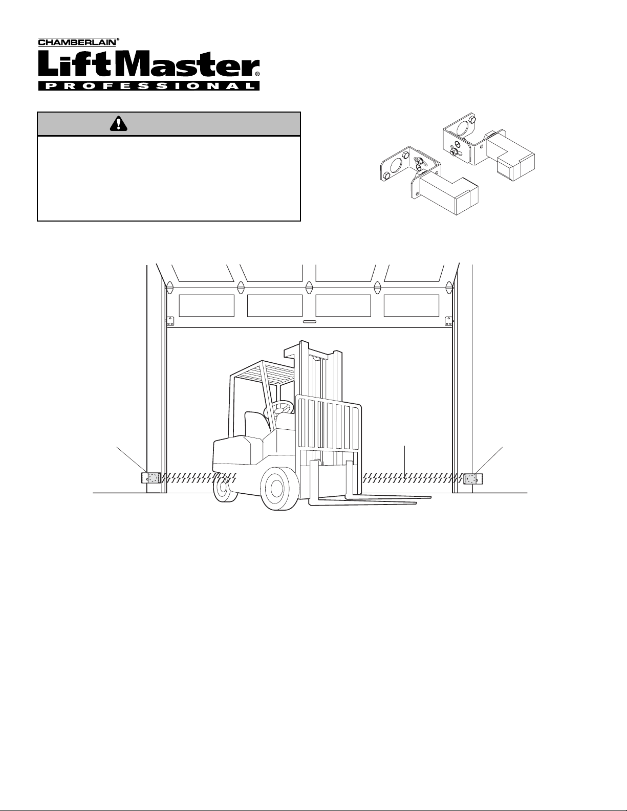
IMPORTANT INFORMATION ABOUT THE SAFETY
REVERSING SENSOR
Be sure power to the opener is disconnected.
When properly connected and aligned, the sensor will detect an
obstacle in the path of its electronic beam. The sending eye
(emitter with an amber indicator light) transmits an invisible light
beam to the receiving eye (receiver with a green indicator light).
If an obstruction breaks the light beam while the door is closing,
the door will stop and reverse to full open position.
The units must be installed inside the garage so that the
sending (emitting)and receiving eyes face each other across
the door, no more than 6" (15 cm) above the floor. Either can
be installed on the left or right of the door as long as the sun
never shines directly into the receiving eye lens.
The brackets must be securely fastened to a solid surface such
as the wall framing. If installing in masonry construction, add a
piece of wood at each location to avoid drilling extra holes in
masonry if repositioning is necessary.
The invisible light beam path must be unobstructed. No part of
the garage door (or door tracks, springs, hinges, rollers or other
hardware) may interrupt the beam while the door is closing. If it
does, use a piece of wood to build out each sensor mounting
location to the minimum depth required for light beam
clearance.
Facing the door from inside the garage
This device is for use ONLY with LiftMaster Commercial Door
Operators. Use on other than recommended equipment voids
warranty, and may cause PROPERTY DAMAGE or SERIOUS
PERSONAL INJURY. Read and follow all instructions.
Have door in full open or closed position and disconnect power to
the garage door opener BEFORE installing the CDO Commercial
Protector System
®
.
WARNING
WARNING
Installation procedures are the
same for all door types.
—Left Side of Garage—
Safety Reversing
Sensor
— Right Side of Garage —
Invisible Light Beam
Protection Area
Safety Reversing
Sensor
Page 2
2
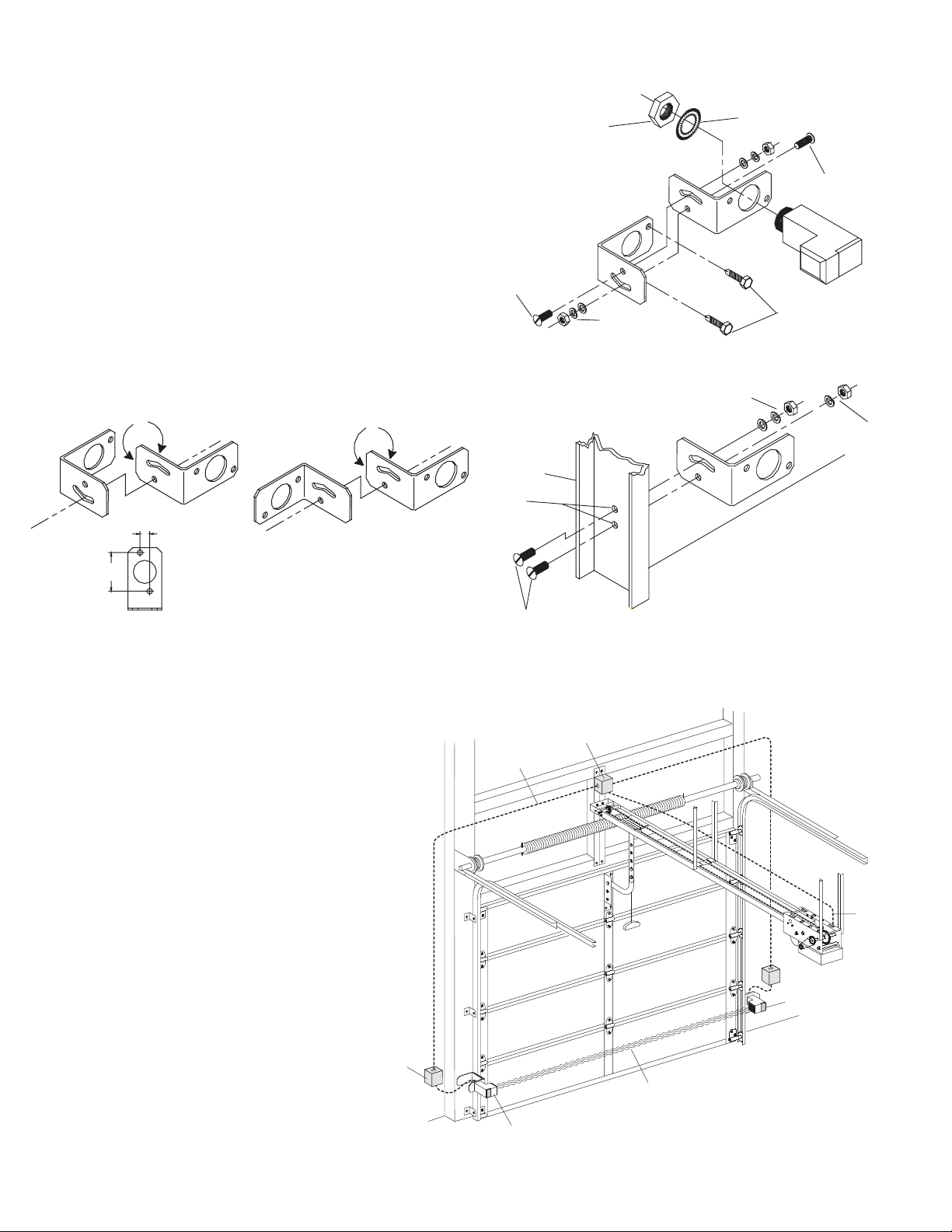
INSTALLING THE BRACKETS
IMPORTANT: Mount sensors 4"-6" (10-15 cm) above the floor.
Do not exceed 6" (15 cm). For sensing above 6" (15 cm), a
second set of eyes would be required.
Floor or Wall Mount
For typical floor or wall mounting applications see Figure 1. If
necessary, see Figure 2 for various assembly options to fit your
application. Always use flat washer next to slot with radius
(Figure 1). Insert track bolts through holes as shown. NOTE:
Putting track bolts in slots will prevent brackets from pivoting.
Attach assembly to wall with lag screws provided. To attach to
concrete use concrete anchors (not provided).
Track Mount
To mount to door track use only one bracket per side
(Figure 3).
To attach vertically to 2" x 4" wall stud and prevent wood from
splitting, bracket may also be rotated with leg on top. Shown
with leg on bottom.
CONDUIT CONNECTIONS
Use a liquid tight fitting (1/2" trade size) with sealing
washer to connect to sensors. The sensors are provided
with 36" long leads. We recommend the use of a liquid
tight junction box near each sensor to make the connection
to the sensor leads. (Figure 4). Use rigid or flexible liquid
tight conduit (depending on local codes) from junction
boxes to operator.
IMPORTANT: Use a minimum size 20 ga. copper wire for
connection between the sensors and the operator.
WIRING CONNECTIONS
CPS-N4: See top of page 3
CPSII-N4: See middle of page 3
CPS-LN4: See page 4 and 5
See Wiring
Connections
Sensor Beam
6" (15 cm) max. above floor
Sensor Beam
6" (15 cm) max. above floor
Invisible Light Beam
Protection Area
Liquid Tight
Conduit
Liquid Tight
Junction Box
Liquid Tight
Junction Box
Figure 4
Hex Mounting Nut
for Sensor
1/4"-20 x 5/8"
Track Bolts
Figure 1 Wall or Floor Mounting
Lock Washer for Sensor
1/4" Flat Washer
1/4" Lock Washer
1/4"-20 Hex Nut
1/4" x 1-1/2"
Lag Screws
1/4"-20 x 5/8"
Track Bolts
Figure 2 Assembly Variations
Assemble to either side
1/2" Hole Spacing
2" Hole Spacing
Flip one bracket and
assemble to either side
Figure 3 Door Track Mounting
1/4" Flat Washer
1/4" Lock Washer
1/4"-20 Hex Nut
1/4" Lock Washer
1/4"-20 Hex Nut
Door
1/4" Drill
Holes
1/4"-20 x 5/8" Track Bolts
Page 3
3
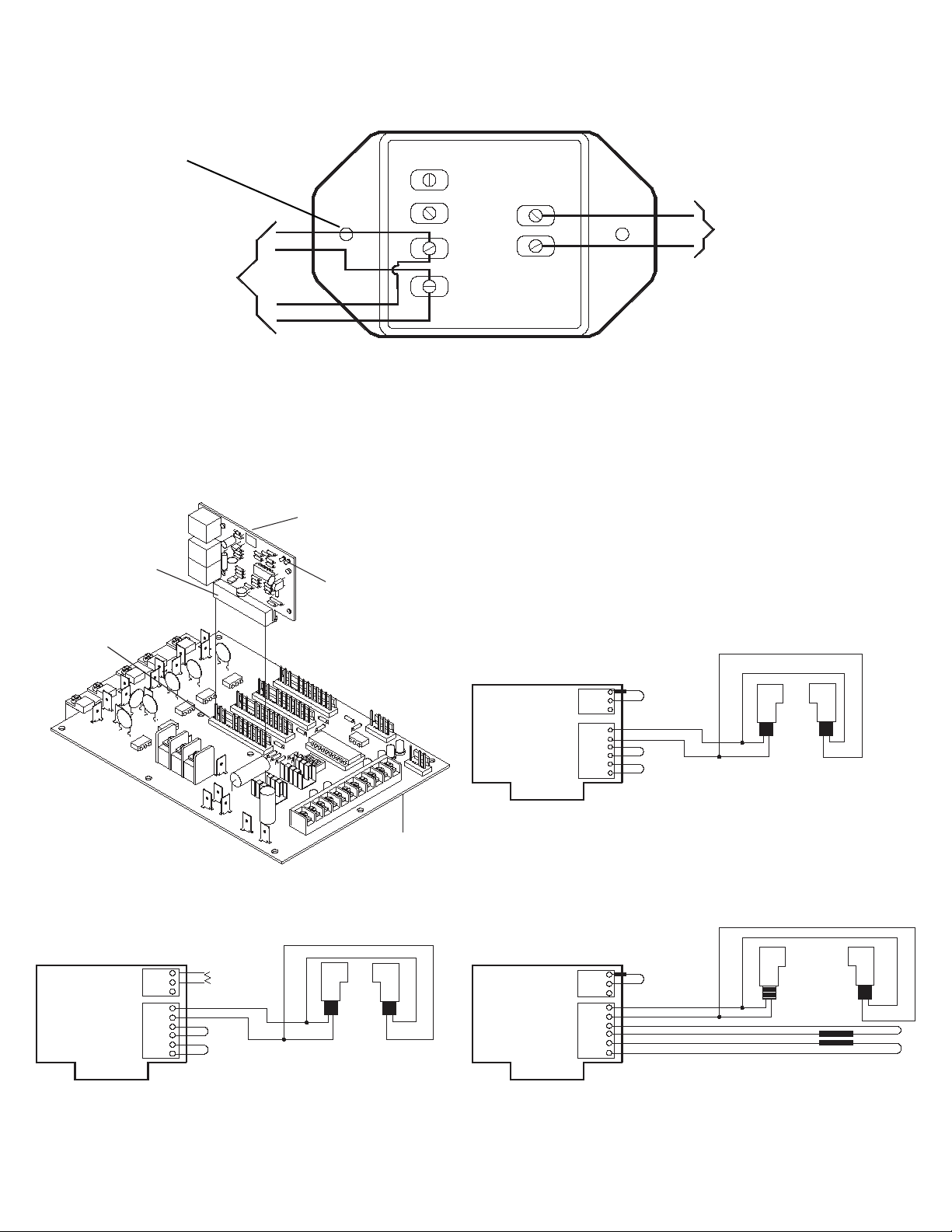
CPS-N4 Wiring Connections
CPSII-N4 Wiring Connections for use with Solid State Logic Control Board
CDO Sensing
Edge Input
To Sending Eye
(Emitter) and
Receiving Eye
(Receiver)
Commercial Protector
Interface
24V
Common
Sensor
Brown
Sensor
Blue
NOTE: Logic 2 Board will have the same connection.
CPSII Option PCB
Terminals
Green Lights
Insert PCB into
any or four slots
IR Protector Only
CDO Motherboard
A
B
C
D
E
F
G
H
I
J
A
B
C
D
E
F
G
H
I
J
IR Protector and 4-Wire Fail Safe Door EdgeIR Protector and 2-Wire Fail Safe Door Edge
A
B
C
D
E
F
G
H
I
J
Page 4

4
CPS-LN4 Wiring Connections for use with Solid State II (Logic Control Board Ver 2)
TO ACTIVATE SAFETY SENSOR EYES
1.
Start with door in the “CLOSED” position.
2. Connect the CPS-LN4 eyes as shown in figure to the left.
Confirm that the LEDs on both eyes are lit.
3. Set DIP switches to desired operating mode. (Refer to
owner’s manual for switch settings.)
4. Run the door through one full close-open-close cycle to
“Learn” the sensor eyes.
NOTE: Test the Safety Sensor Eyes operation by interrupting
the eyes while closing the door.
5. Once the sensor eyes are “Learned” and it becomes
necessary to remove the sensors, the sensors will
need to be “unlearned” by setting DIP switch to “Timer
to Close” mode and pressing the Close Button.
Brown
Blue
CPS-LN4 Wiring Connections for use with LGO Operator
IR PROTECTOR ONLY IR PROTECTOR AND SAFETY EDGE
Important Note: When sensors (IRs) are used, wiring mode
B2 must be reprogrammed. Sensors must be connected and
sending a pulse prior to programming. See LGO owner’s
manual for further information.
ON
ON
SET
TIMER
TO CLOSE
1 2 3 4
OFF
Page 5

5
CPS-N4 Wiring Connections for use with LiftMaster Operators Featuring Estate Series X3 or B3 Control Board
CPS-N4 Wiring Connections for use with LiftMaster Operators Featuring GL Control Board
Page 6

6
Testing the Protector System
®
TEST THE CDO COMMERCIAL PROTECTOR
SYSTEM
®
• Press the OPEN button to fully open the door.
• Press the CLOSE button to close the door.
• Obstruct the light beam while the door is closing. The door
should stop and reverse.
The door opener will not close if the indicator light in
either sensor is not glowing steadily, alerting you to the
fact that the sensor is misaligned or obstructed.
Troubleshooting
1. If the sending eye and receiving eye indicator lights do not
glow steadily after installation, check for:
• Electric power to the opener.
• A short in the Blue or Brown wires.
• Incorrect wiring between sensors and interface.
• An open wire (wire break).
2. If receiving eye indicator light is off (and the invisible light
beam path is not obstructed), check for an open wire to the
receiving eye.
Without a properly working CDO Commercial Protector System®,
persons (particularly children) could be SERIOUSLY INJURED or
KILLED by a closing garage door. Repeat this test once a month.
Professional service is required if the openercloses the door when
the CDO Protector System
®
is obstructed.
WARNING
NOTE: For non-solid state operators, if the door is stopped in a
mid position, activation of the sensors will cause the door to
open. This is similar to activating a sensor edge.
3. If the sending eye and receiving eye indicator lights are both
lit but interrupting the photo eyes does not cause the door to
reverse when closing, refer to “To Activate Safety Sensor
Eyes” on page 4.
WARNING
Page 7

7
Replacement Parts
CPS-N4 Commercial Protector Interface . . . .41K4629
CPSII-N4 CPSII PC Board . . . . . . . . . . . . . . . .41K4654
CPS-N4 / CPSII-N4 / CPS-LN4
Sensor Hardware Kit . . . . . . . . . . .K77-16011
Emitter . . . . . . . . . . . . . . . . . . . . . . .50-15514
Receiver . . . . . . . . . . . . . . . . . . . . .50-15515
How to Order Repair Parts
Our large service organization spans America. Installation and
service information are available six days a week. Call our toll free
number: 1-800-528-2806
HOURS: (Mountain Std. Time)
7:00 A.M. to 3:30 P.M. Monday through Saturday
When ordering repair parts, please supply the following
information:
PART NUMBER DESCRIPTION MODEL NUMBER
Address orders to:
THE CHAMBERLAIN GROUP, INC.
Technical Support Group
6020 S. Country Club Road
Tucson, Arizona 85706
Page 8

© 2005, The Chamberlain Group, Inc.
01-16013K All Rights Reserved Printed in Mexico
 Loading...