

Page 1
1
CDO Commercial Protector System
®
OWNER’S MANUAL
For use with Models CPS, CPSII and CPS-L
Install the Protector System
®
IMPORTANT INFORMATION ABOUT THE SAFETY
REVERSING SENSOR
Be sure power to the opener is disconnected.
When properly connected and aligned, the sensor will detect an
obstacle in the path of its electronic beam. The sending eye
(emitter with an amber indicator light) transmits an invisible light
beam to the receiving eye (receiver with a green indicator light).
If an obstruction breaks the light beam while the door is closing,
the door will stop and reverse to full open position.
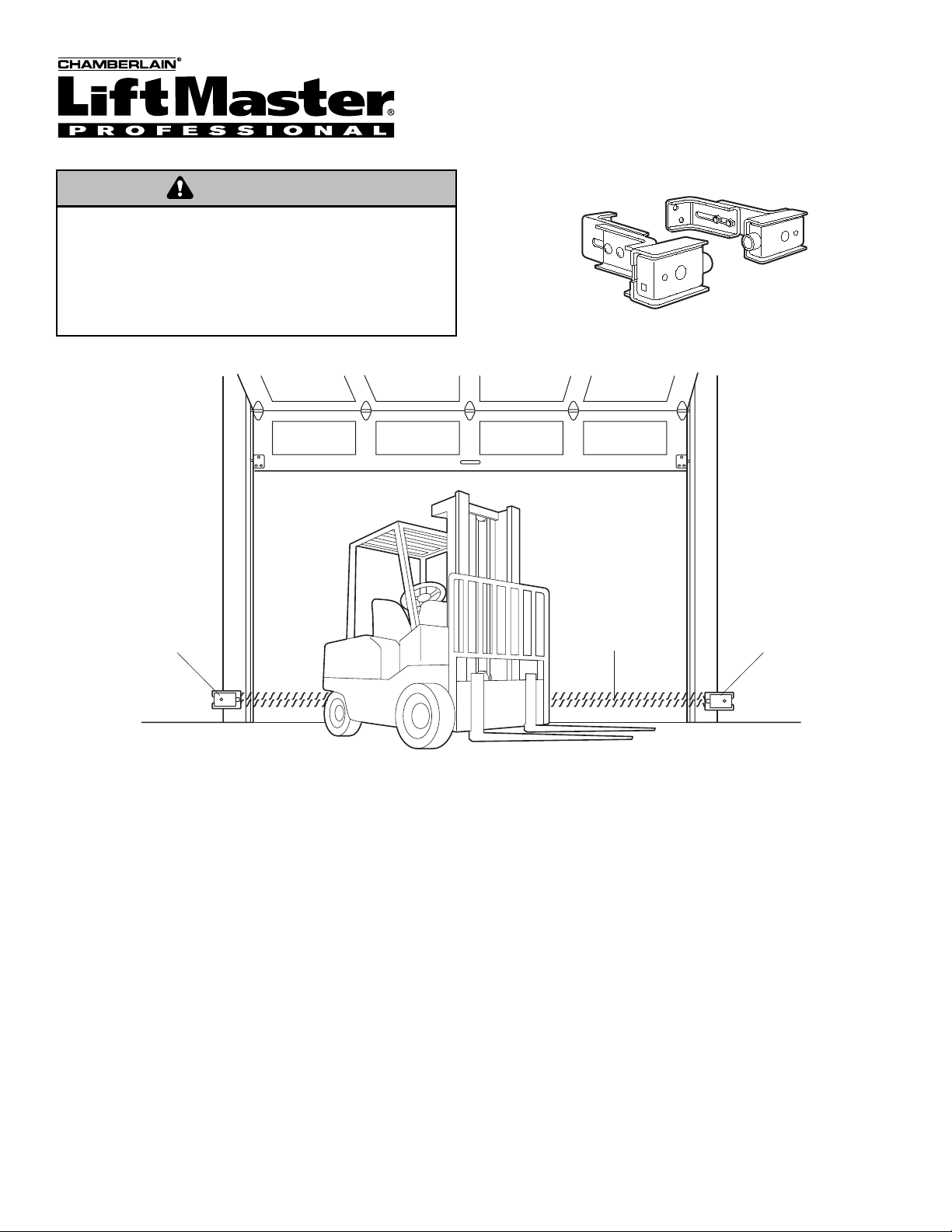
The units must be installed inside the garage so that the
sending (emitting)and receiving eyes face each other across
the door, no more than 6" (15 cm) above the floor. Either can
be installed on the left or right of the door as long as the sun
never shines directly into the receiving eye lens.
The brackets must be securely fastened to a solid surface such
as the wall framing. If installing in masonry construction, add a
piece of wood at each location to avoid drilling extra holes in
masonry if repositioning is necessary.
The invisible light beam path must be unobstructed. No part of
the garage door (or door tracks, springs, hinges, rollers or other
hardware) may interrupt the beam while the door is closing. If it
does, use a piece of wood to build out each sensor mounting
location to the minimum depth required for light beam
clearance.
Facing the door from inside the garage (installation procedures are the same for all door types).
This device is for use ONLY on LiftMaster Commercial Door
Operators. Use on other than recommended equipment voids
warranty, and may cause PROPERTY DAMAGE or SERIOUS
PERSONAL INJURY. Read and follow all instructions.
Have door in full open or closed position and disconnect power to
the garage door opener BEFORE installing the CDO Commercial
Protector System
®
.
WARNING
WARNING
—Left Side of Garage—
Safety Reversing
Sensor
— Right Side of Garage —
Invisible Light Beam
Protection Area
Safety Reversing
Sensor
Page 2
2
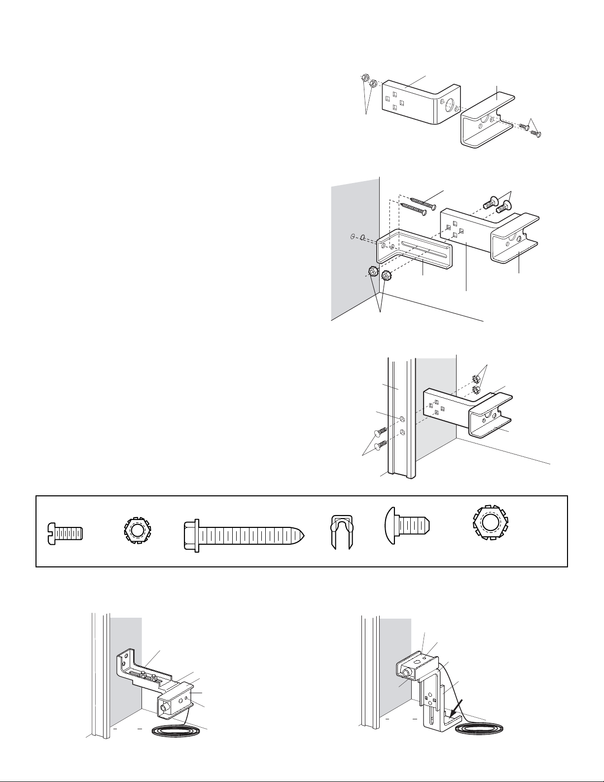
INSTALLING THE BRACKETS
Figures 1, 2 and 3 show recommended assembly of the
bracket(s) and
“C” wrap based on the wall installation of the
sensors on each side of the door as shown on page 1 or on the
door tracks themselves.
Figures 4 and 5 are variations which may fit your installation
requirements better. Make sure the wraps and brackets are
aligned so the sensors will face each other across the door.
Wall or Door Track Installation Procedure
• Fasten the “C” wraps to the mounting brackets having
square holes, using hardware shown (Figure 1).
Wall Installation Procedure
• Connect each assembly to a slotted bracket, using the
hardware shown (Figure 2). Note alignment of brackets for
left and right sides of the door.
• Finger tighten the lock nuts.
• Use bracket mounting holes as a template to locate and drill
(2) 3/16" diameter pilot holes on both sides of the garage
door, 4"-6" (10-15 cm) above the floor. Do not exceed
6" (15 cm).
• Attach bracket assemblies with 1/4"x1-1/2" lag screws
(Figure 2).
• Adjust right and left side bracket assemblies to the same
distance out from mounting surface. Make sure all door
hardware obstructions are cleared. Tighten the nuts securely.
Door Track Installation Procedure
• Discard slotted bracket. Drill 3/8" holes in each track and
fasten securely with hardware (Figure 3).
HARDWARE SHOWN ACTUAL SIZE
Figure 1 WALL or DOOR Track Installation
Mounting Bracket
With Square Holes
#10-32
Lock Nuts
“C” Wrap
#10-32x3/8"
Screws
Figure 2 WALL Installation
Inside
Wall
1/4x1-1/2"
Lag Screws
Mounting Bracket
with Slot
1/4"-20
Lock Nuts
1/4-20x1/2" Carriage Bolts
(with square shoulder)
“C” Wrap
Mounting Bracket
with Square Holes
Figure 3 DOOR Track Installation
Inside
Wall
Door Track
1/4" Lock Nuts
Mounting Bracket
with Square Holes
Screw
#10-32x3/8"
Lock Nut
#10x32
Figure 4 Alternate Wall Mount
Inside
Wall
Floor
Mounting Bracket
with Slot
Mounting Bracket
with Square Holes
“C” Wrap
Sensor
with wire
Indicator Light
Lag Screw 1/4x1-1/2"
Drill 3/8"
Holes
1/4-20x1/2"
Carriage Bolts
Staples
Carriage Bolts
1/4"-20x1/2"
Lock Nut
1/4"-20
Figure 5 Alternate Floor Mount
Inside
Wall
“C” Wrap
Floor
Sensor with wire
Indicator Light
Mounting Bracket
with Square Holes
Mounting Bracket
with Slot
Attach with
concrete
anchors
(not provided)
“C” Shaped
Wrap
Page 3
3
HARDWARE SHOWN ACTUAL SIZE
Bell Wire
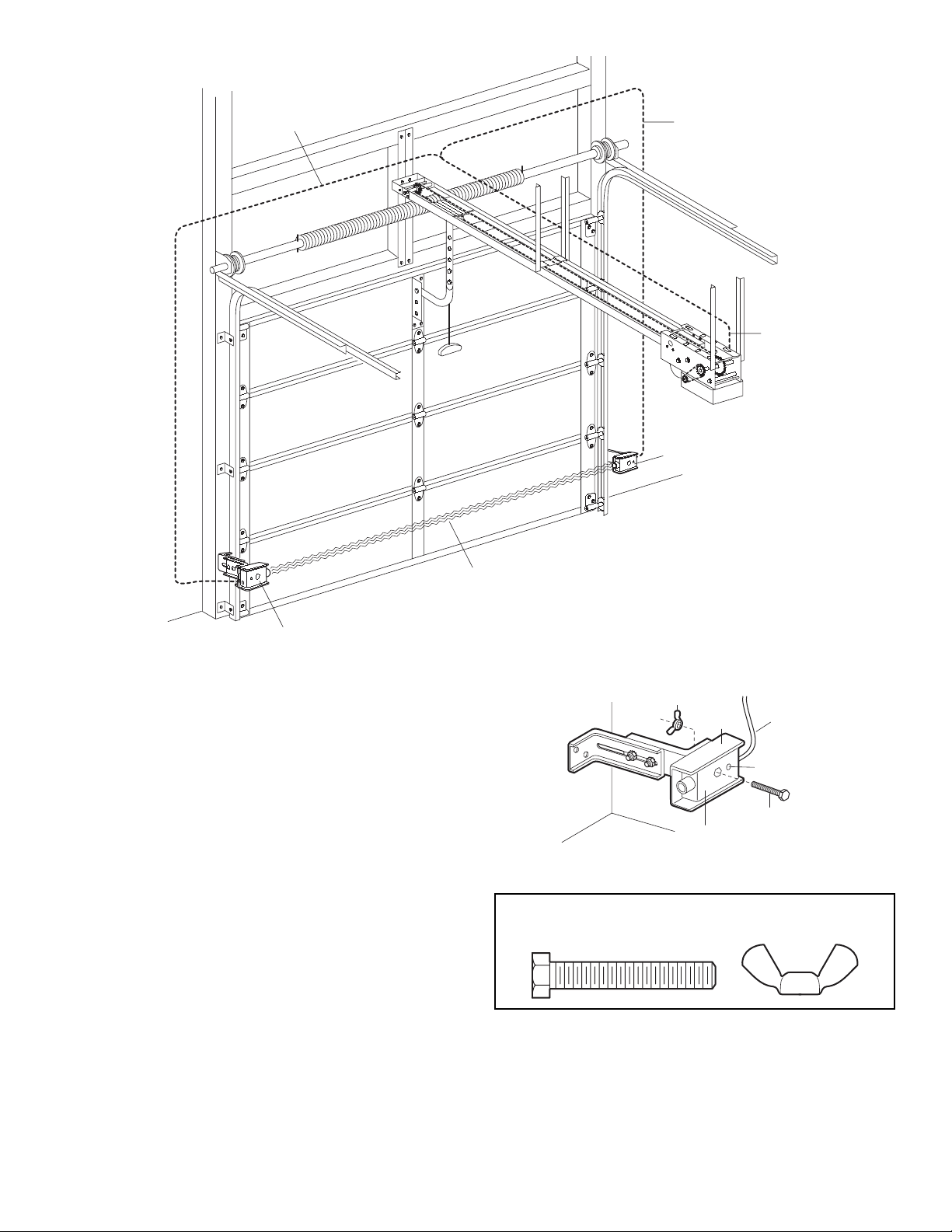
MOUNTING AND WIRING THE SAFETY SENSORS
• Insert the wire connector into each sensor and push until you
hear a click. The white tab on the sensor should be flush with
the back of connector.
• Center each sensor unit in a “C” wrap with lenses pointing
toward each other across the door.
• Secure sensors with hardware as shown. Finger tighten the
wing nut on the receiving eye to allow for final adjustment.
Securely tighten the sending eye wing nut.
• Run paired wires from both sensors to the opener (Figure 6).
Use insulated staples to secure the wire to the wall and
ceiling.
• For wiring connections, see following pages:
CPS page 4
CPS-L page 4
CPSII page 5
ALIGNING THE SAFETY SENSORS
• Power up the opener. Green indicator lights in both the
sending and receiving eyes will glow steadily if wiring
connections and alignment are correct.
If the receiving eye indicator light is not glowing steadily
(and the invisible light beam path is not obstructed),
alignment is required.
• Loosen the receiving eye wing nut to allow slight rotation
of unit. Adjust sensor vertically and/or horizontally until the
green indicator light glows steadily.
• When indicator lights are glowing steadily in both units,
tighten the wing nut in the receiving eye unit.
Figure 6
Secure Wire with
Insulated Staples
Connect Wire
to Commercial
Protector Interface
Safety Sensor Beam
6" (15 cm) max. above floor
Invisible Light Beam
Protection Area
Safety Sensor Beam
6" (15 cm) max. above floor
Wing Nut
“C” Wrap
Sensor
1/4-20x1-1/2"
Hex Bolt Wing Nut
Wire
Indicator Light
1/4-20 x 1-1/2"
Hex Bolt
Page 4

4
CPS Wiring Connections
TO ACTIVATE SAFETY SENSOR EYES
1.
Set DIP switch on logic board to “Set Timer to Close”
mode. (Refer to illustration below.)
2. Press the CLOSE button to clear timer. If using “Timer to
Close,” set delay time now.
3. Set DIP switch back to desired operating mode. (Refer to
owner’s manual for DIP switch settings.)
4. Starting with the door in the close position, run the door
through one full open-close cycle to “Learn” the sensor
eyes.
5. After the open-close cycle:
a) Confirm the the LEDs on both sensor eyes are lit.
b) Test the Safety Sensor Eyes operation by interrupting
the sensors while closing the door.
CPS-L Wiring Connections for use with Solid State II (Logic Control Board Ver 2)
White/Black
White
Once eyes are connected it will be necessary to set DIP switch
to Timer to Close mode (refer to “Activate Photo Eyes”
instructions below).
WARNING
WARNING
WARNING
CDO Sensing
Edge Input
To Sending Eye
(Emitter) and
Receiving Eye
(Receiver)
Commercial Protector
Interface
24V
Common
Sensor
White
Sensor
White/Black
Logic 2 Shown
CAUTION
SET
TIMER
TO CLOSE
ON
ON
1 2 3 4
OFF
Page 5

5
CPSII Wiring Connections for use with Solid State Logic Control Board
White
White/Black
White
White/Black
White
White/Black
Logic 1 Shown
CPSII PROTECTOR ONLY
CPSII PROTECTOR AND 2-WIRE FAIL SAFE DOOR EDGE
CPSII PROTECTOR AND 4-WIRE FAIL SAFE DOOR EDGE
Green Lights
CPSII
Option PCB
CDO
Motherboard
Insert PCB into any
available slot
A
B
C
D
E
F
G
H
I
J
270K
Terminal
Ω Resistor
2-wire Edge
A
B
C
D
E
F
G
H
I
J
270K
Door Edge Contacts
Ω Resistor
A
B
C
D
E
F
G
H
I
J
4-wire Edge
Page 6

6
Testing the Protector System
®
TEST THE CDO COMMERCIAL PROTECTOR
SYSTEM
®
• Press the OPEN button to fully open the door.
• Press the CLOSE button to close the door.
• Obstruct the light beam while the door is closing. The door
should stop and reverse.
The door opener will not close if the indicator light in
either sensor is not glowing steadily, alerting you to the
fact that the sensor is misaligned or obstructed.
Troubleshooting
1. If the sending eye and receiving eye indicator lights do not
glow steadily after installation, check for:
• Electric power to the opener.
• A short in the White or White/Black wires.
• Incorrect wiring between sensors and interface.
• An open wire (wire break).
2. If receiving eye indicator light is off (and the invisible light
beam path is not obstructed), check for an open wire to the
receiving eye.
Without a properly working CDO Commercial Protector System®,
persons (particularly children) could be SERIOUSLY INJURED or
KILLED by a closing garage door. Repeat this test once a month.
Professional service is required if the opener closes the door when
the CDO Protector System
®
is obstructed.
WARNING
NOTE: For non-solid state operators, if the door is stopped in a
mid position, activation of the sensors will cause the door to
open. This is similar to activating a sensor edge.
3. CPS-L Only: If the sending eye and receiving eye indicator
lights are both lit but interrupting the photo eyes does not
cause the door to reverse when closing, refer to “To Activate
Safety Sensor Eyes” on page 4.
WARNING
Page 7

7
Replacement Parts
How to Order Repair Parts
Our large service organization spans America. Call our toll free
number: 1-800-528-2806
When ordering repair parts, please supply the following
information:
PART NUMBER DESCRIPTION MODEL NUMBER
Address orders to:
THE CHAMBERLAIN GROUP, INC.
Technical Support Group
6020 S. Country Club Road
Tucson, Arizona 85706
CPS Commercial Protector Interface . . . .41K4629
CPSII CPSII PC Board . . . . . . . . . . . . . . . .41K4654
CPS / CPSII / CPS-L
Sensor Hardware Kit . . . . . . . . . . . .41D4116
CPSII / CPS-L
Receiver . . . . . . . . . . . . . . . . . . .001A5053-9
Page 8

© 2006, The Chamberlain Group, Inc.
01-16691C All Rights Reserved
 Loading...