

Page 1
1
Protector System
®
OWNER’S MANUAL
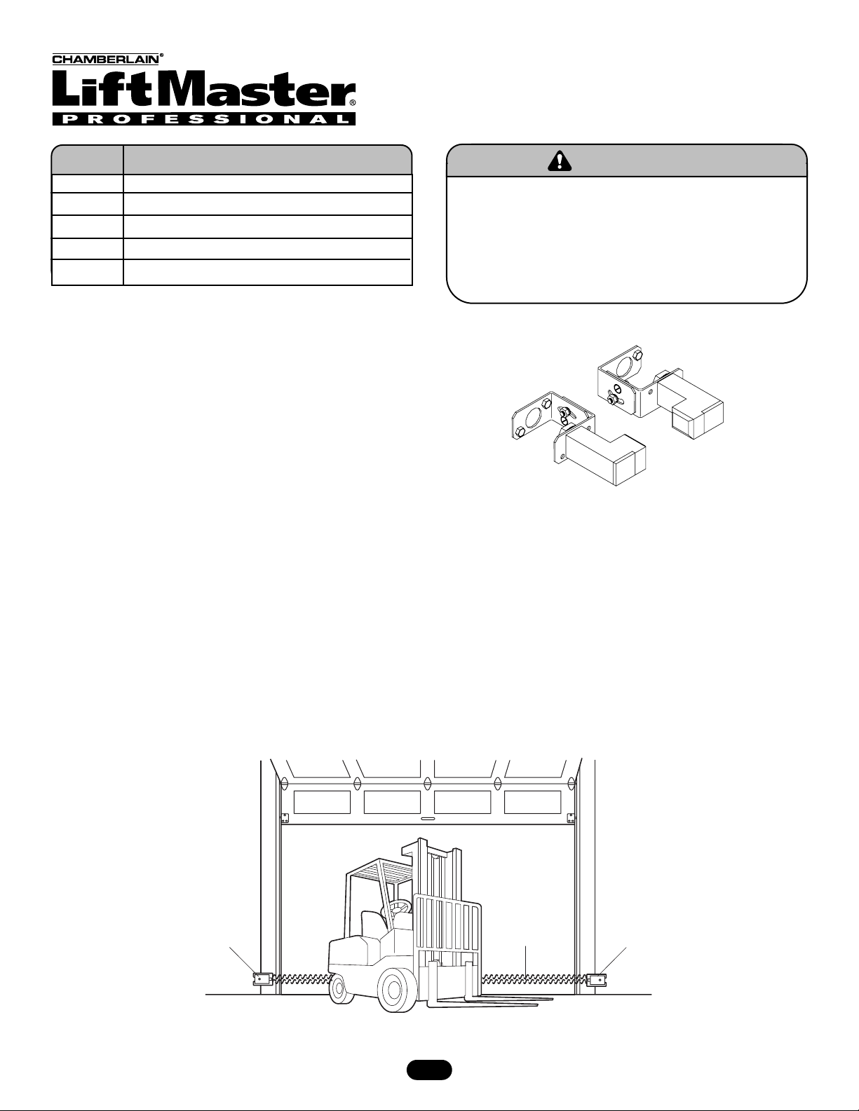
Models: CPS-N4, CPS3-N4 and CPS-LN4
Application
CPS-N4: Suitable for use on all operators with a reversing
N.O. contact input.
CPS-LN4: Direct connect photo eyes suitable with Logic 2 and
Logic 3 operators.
CPS-N4: Suitable for use with Logic 2 and Logic 3 operators
when more than (1) set of photo eyes are required.
Example: Fire station, use (1) set of direct connect
CPS-LN4 and CPS-N4.
Install the Protector System
®
IMPORTANT INFORMATION ABOUT THE SAFETY REVERSING
SENSOR
Be sure power to the operator is disconnected.
When properly connected and aligned, the sensor will detect an
obstacle in the path of its electronic beam. The sending eye
(emitter with an amber indicator light) transmits an invisible
light beam to the receiving eye (receiver with a green indicator
light). If an obstruction breaks the light beam while the door is
closing, the door will stop and reverse to full open position.
The units must be installed inside the garage so that the
sending (emitting) and receiving eyes face each other across the
door, no more than 6" (15 cm) above the floor. Either can be
installed on the left or right of the door as long as the sun never
shines directly into the receiving eye lens.
The brackets must be securely fastened to a solid surface such
as the wall framing. If installing in masonry construction, add a
piece of wood at each location to avoid drilling extra holes in
masonry if repositioning is necessary.
The invisible light beam path must be unobstructed. No part of
the garage door (or door tracks, springs, hinges, rollers or other
hardware) may interrupt the beam while the door is closing. If it
does, use a piece of wood to build out each sensor mounting
location to the minimum depth required for light beam
clearance.
—
Facing the door from inside the garage (installation procedures are the same for all door types).
Part # Description
41K4629 CPS-N4 - Commercial Protector Interface
CPS3CARD CPS3 PC Board (Only)
K77-16011 Sensor Hardware Kit
50-15514 Emitter
50-15515 Receiver
To reduce the risk of SERIOUS INJURY or DEATH,
• This device is for use ONLY on LiftMaster®Commercial
Door Operators.
• Disconnect power BEFORE installing the Commercial
Protector System®.
• Read and follow ALL instructions.
WARNING
WARNING
—Left Side of Garage—
Safety Reversing
Sensor
Invisible Light
Beam Protection
Area
— Right Side of Garage
Safety Reversing
Sensor
Page 2
2
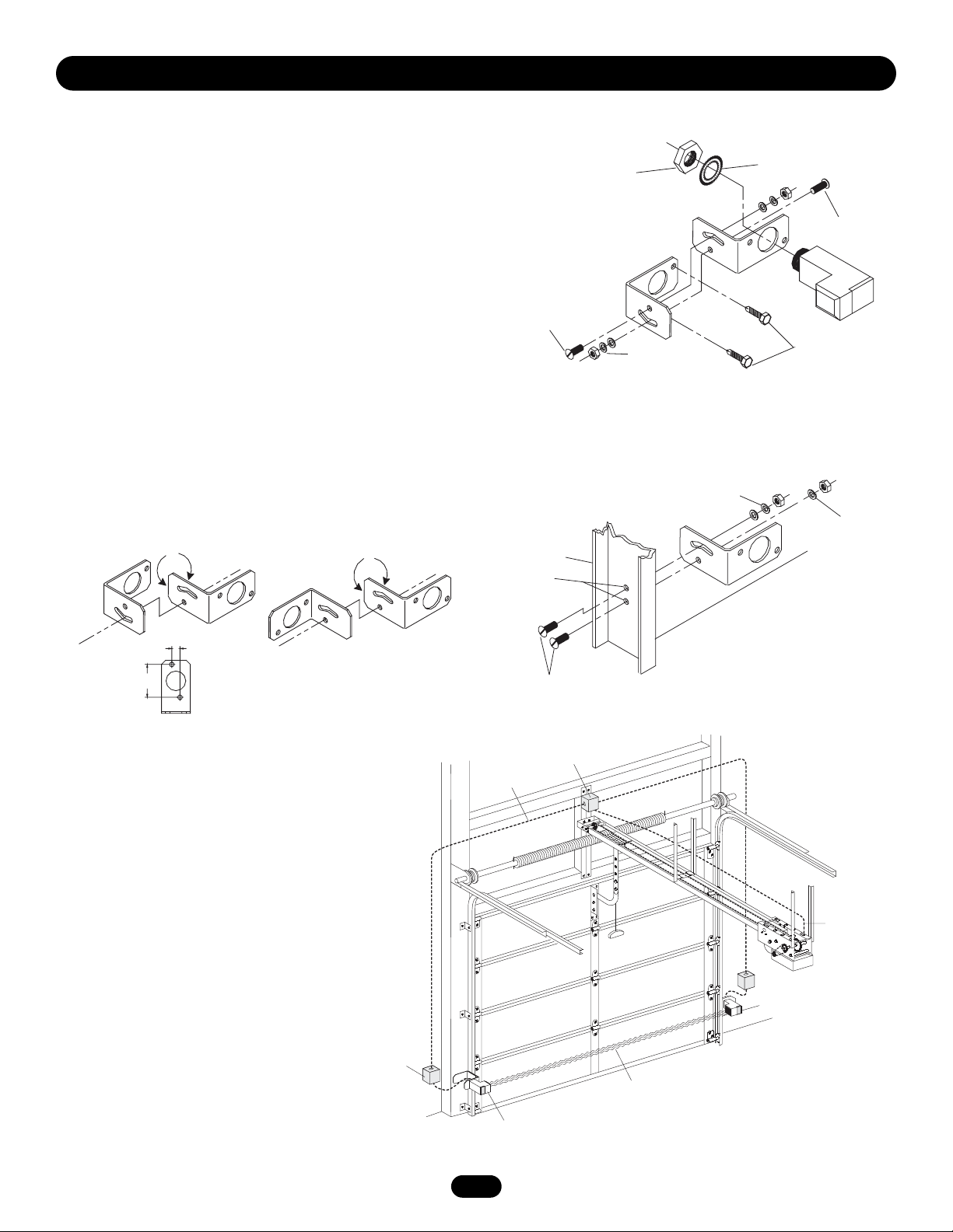
Figure 4
INSTALLING THE BRACKETS
Be sure power to the operator is disconnected. Install and align
the brackets so the sensors will face each other across the
door/gate, with the beam no higher than 6" (15 cm) above the
floor. For sensing above 6" a second set of eyes would be
required.
Floor or Wall Mount Installation (Figure 1)
If necessary, see Figure 2 for various assembly options to fit
your application. Always use flat washer next to slot with radius
as shown in Figure 3. Insert track bolts through holes as shown.
NOTE: Putting track bolts in slots will prevent brackets from
pivoting. Attach brackets to wall with lag screws provided.
Fasten to the floor with concrete anchors (not provided).
Track Installation (Figure 3)
To mount to door track use only one bracket per side.
To vertically attach to 2" x 4" wall stud it may become necessary
to rotate bracket to prevent wood from splitting.
Figure 1
Floor or Wall Mounting
See Wiring
Connections
Sensor Beam
6" (15 cm) max. above floor
Sensor Beam
6" (15 cm) max. above floor
Invisible Light Beam
Protection Area
Liquid Tight
Conduit
Liquid Tight
Junction Box
Liquid Tight
Junction Box
Door Track Mounting
Figure 2
CONDUIT CONNECTIONS
Use a liquid tight fitting (1/2" trade size) with
sealing washer to connect to sensors. The
sensors are supplied with 36" long leads. We
recommend the use of a liquid tight junction
box near each sensor to make the connection to
the sensor leads (Figure 4). Use rigid or flexible
liquid tight conduit (depending on local codes)
from junction boxes to operator.
IMPORTANT: Use a minimum size 20 ga. copper
wire for connection between the sensors and
the operator.
WIRING CONNECTIONS:
CPS-N4 - See page 3
CPS3-N4 - See page 4
CPS-LN4 - See page 5
Figure 3
Assembly Variations
INSTALLATION FOR LIFTMASTER COMMERCIAL OPERATORS
Assemble to either side
Flip one bracket and
assemble to either side
1/4"-20 x 5/8"
Track Bolts
1/4" Drill
Holes
Hex Mounting Nut
for Sensor
Door
1/4" Flat Washer
1/4" Lock Washer
1/4"-20 Hex Nut
1/4" Flat Washer
1/4" Lock Washer
1/4"-20 Hex Nut
Lock Washer for Sensor
1/4"-20 x 5/8"
Track Bolts
1/4" x 1-1/2"
Lag Screws
1/4" Lock Washer
1/4"-20 Hex Nut
1/2" Hole Spacing
2" Hole Spacing
1/4"-20 x 5/8" Track Bolts
Page 3
3
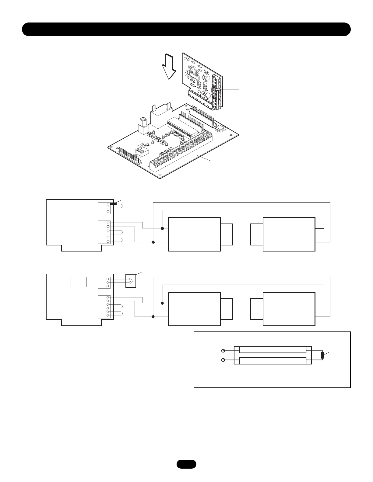
CPS3-N4 Wiring Connections for use with Logic Operators (L2 or L3)
Commercial Door Opener Protector System®Only
Commercial Door Opener Protector System®and 2-Wire Fail Safe Door Edge
WIRING FOR LIFTMASTER COMMERCIAL OPERATORS
CPS3 protector and 2-wire fail-safe door edge connections
For a 2-wire safety edge with an embedded resistor;
1. Remove the 270K resistor from the A & B terminals.
2. Connect 2-wire coil cord or cord reel to the A & B terminals.
For a 4-wire safety edge using a 2-wire coil cord;
1. Remove the 270K resistor from the A & B terminals.
2. Add the resistor to 2 of the 4 wires at the safety edge,
connect the coil cord to the other 2 safety edge wires
(Figure 1).
3. Connect the 2-wire coil cord or cord reel to the A & B
terminals.
NOTE: If the LiftMaster®photo eyes are not being connected
you must remove the JU1 and R16 resistors from the
CPS3CARD.
Insert Logic Board into
any available slot
I
270KΩ Resistor
Brown
Blue
A
B
C
D
E
F
G
H
J
2-Wire Edge
JU1
R16
A
B
C
D
Brown
E
F
G
H
I
J
Blue
CPS3
Option Logic Board
Logic 3 Board Shown
Figure 1
Terminal A
Terminal B
270K
Resistor
2-Wire s.e. with Embedded Resistor
or
4-Wire s.e. Adding the Resistor
Page 4

4
NOTE: When using a 4-wire door edge only (without the LiftMaster®photo eyes), you must remove the JU1 and R16 resistors from the
CPS3 card. Logic 3 Board will have the same connection. The maximum door edge resistance should be less than 1000 ohms as
measured between any 4 conductors. This measurement should be taken when the door edge is in the closed contact state.
Commercial Door Opener Protector System
®
and 4-Wire Fail Safe Door Edge
A
B
C
D
E
F
G
H
I
J
270KΩ Resistor
Brown
Blue
4-Wire Edge
Door Edge Contacts
JU1
R16
*NOTES: Typical connections shown. On mechanical operators always refer to diagram that came with the operator.
For gate operator controls not listed above, refer to their respective owner’s manuals.
Operator/Auxiliary Point
Connections
Connection at CPS CPS-N4 Interface Box
24V Common
Sensor Black
or Brown
Sensor White
or Blue
Sensing Edge
Input (1/2)
Sensing Edge
Input (2/2)
Diagram
Reference
Page
Emitter Wire
at CPS
CPS-N4
Emitter Black
or Brown
Emitter White
or Blue
Receiver Wire
at CPS
CPS-N4
Receiver Black
or Brown
Receiver
White or Blue
Mechanical
Terminal
at Operator 3* Wire Nut* 3* 10* 7
Logic 2
Terminal
at Operator 12 13 8 11 5
Logic 3
Terminal
at Operator 13 14 8 11 5
HCT Terminal
OmniControl
Surge
Suppressor
Terminals
13 11 3 4 7
Elite Gate
Application 1
OmniBoard
Terminals
Sensor (1/2) Sensor (1/2)
7
OmniControl
Surge
Suppressor
Terminals
13 11
Elite Gate
Application 2
OmniControl
Surge
Suppressor
Terminals
13 11 3 4 7
Estate Series
with X3 or B3
Control Board
at Operator
TB7 1/2
Available
TB7 2/2
Available
TB3 1/3
See page 5
for inside vs
outside
photoeye
TB3 2/3
See page 5
for inside vs
outside
photoeye
5
Operators
with GL
Control Board
at Operator
External
Radio
Terminal
Strip R1
External
Radio
Terminal
Strip R2
GL Board
Terminal 5
GL Board
Terminal 9 or
10 See page 6
for inside vs
outside
photoeye
6
Page 5

5
CPS-N4 Wiring Connections for use with Estate
Series X3 or B3 Control Board
WIRING FOR LIFTMASTER GATE OPERATORS
The eyes are required for all timer modes and fail-safe modes.
The eyes are automatically learned once connected and
operating correctly.
To Unlearn Eyes
• For Logic 3, remove the eyes from the circuit. Set the selector
switch to “DIAG” mode, then press and hold the stop button
for 5 seconds until the “MAS” LED blinks. the eyes LED
should be off. Set the selector switch back to the
desired mode.
• For Logic 2, remove the eyes from the circuit board. Turn dip
switches 1 and 2 off, and 3 and 4 on. Then, push the open
button twice, the close button twice, and the stop button
twice. Return dip switches back to desired mode.
CPS-N4 Wiring Connections
CPS-LN4 Wiring Connections for use with
Logic Operators [L2 or L3]
WIRING FOR LIFTMASTER COMMERCIAL OPERATORS
24Vac/Vdc
Power Supply
To Sending Eye
(Emitter) and
Receiving Eye
(Receiver)
Commercial Protector Interface
24V
Common
Sensor
Brown
Sensor
Blue
Commercial Door Operator N.O.
Sensing Edge Input
Brown Blue
1
543
2
Connections shown good for
Logic 2 or Logic 3
131211
109876
14
NOTE: Depending on where you will
place the photo eye, you can use the
inside photo or the outside photo.
24V
Common
Emitter
Receiver
Sensor
Brown
Sensor
Blue
Inside Photo
TB3
Outside Photo
TB7
Smart Gate
X3/B3 Board
24Vac Output
Page 6

6
CPS-N4 Wiring Connections for use with Elite
®
Omni Control Board Operators
Application 1
Wiring the Protector Interface to the Sensor Alarm causes
operator to reverse only a few inches before stopping.
WIRING FOR LIFTMASTER COMMERCIAL OPERATORS
ALARM SENSOR
OR
CPS-N4 Wiring Connections for use with GL
Control Board
24V
Common
Sensor
Brown
Sensor
Blue
NOTE: Depending on where you will
place the photo eye, you can use the
input 9 for safety open or the input
10 for safety close.
Emitter
Receiver
FETY EXIT
ALARM SENSOR
DC-BACKUP
CK ALARM
M/S LINK
ARMED
SYSTEM ON
SENSORS
1 3
ALARM
SENSOR
COMMAND
DEPT.
PROCESSED
FIRE
EXIT
LOOP
1 3
STRIKE
SAFETY
REVERSE
OPEN
LOOP
SENSOR
TIMER
OFF
OPEN LEFT
RADIO
RECEIVER
CENTER
LOOP
60
ON
OPEN RIGHT
1 3
GATE
LOCKED
RESET
MOTOR
POWER
3
OVERLOAD
MADE IN USA
OPEN
STOP CLOSE
GG BB
M
/S LinkM/S Link
24V
Common
Sensor
Brown
Sensor
Blue
®
OmniControl Sur
Center
Center
AA
Patent PendingPatent Pending
++
––
Strike
Strike
O
O
pe
pe
n
n
R
R
ad
ad
io
Pu
Pu
s
s
h
h
Bu
Bu
P/N Q410
Fire Dept
Fire Dept
Strike Open
Strike Open
Push Button
Push Button
Patent Pending
Patent Pending
P/N Q410
++
––
Radio
Radio
Receiver
Receiver
ge Suppressor
Safety
Safety
Exit
Exit
Loop
Loop
Loop
Loop
Loop
Loop
Key Switch
Key Switch
io
tt
tt
on
on
R
R
ec
ec
eiver
eiver
Class 2
Class 2
Supply
Supply
2
2
4
4
V
V
o
o
lts
lts
D
D
C
C
13
11
Emitter
Receiver
Page 7

7
Testing the Protector System
®
Test the Commercial Protector System
®
• Press the OPEN button to fully open the door.
• Press the CLOSE button to close the door.
• Obstruct the light beam while the door is closing. The door
should stop and reverse.
The operator will not close if the indicator light in either
sensor is not glowing steadily, alerting you to the fact that the
sensor is misaligned or obstructed.
NOTE: For non-solid state operators, if the door is stopped in a
mid position, activation of the sensors will cause the door to
open. This is similar to activating a sensor edge.
TROUBLESHOOTING
1. If the sending eye and receiving eye indicator lights do not
glow steadily after installation, check for:
• Electric power to the opener.
• A short in the Blue or Brown wires.
• Incorrect wiring between sensors and interface.
• An open wire (wire break).
2. If receiving eye indicator light is off (and the invisible light
beam path is not obstructed), check for alignment of the eyes
and/or an open wire to the receiving eye.
To reduce the risk of SERIOUS INJURY or DEATH, the
Commercial Protector System®must be properly installed
and working.
WARNING
WARNING
FKeF
Ke
C
enter
Lo
o
p
C
enter
Lo
o
p
S
a
f
et
y
Loop
S
a
f
et
y
Loop
Exit
Lo
o
p
Exit
Lo
o
p
OmniControl Surge S
Application 2
If an obstruction breaks the light beam while the door is closing,
the door will stop and reverse to full open position.
CPS-LN4 Only
3. If the sending eye and receiving eye indicator lights are both
lit, but interrupting the photo eyes does not cause the door to
reverse when closing, check both eyes and make sure one
eye is the sending and the other is a receiving eye.
NOTES:
1. Direct sunlight to the sending eye may cause operator from
closing even when both the sending and receiving indicator
lights are illuminated. A protective cover shielding both eyes
from direct sunlight will resolve this issue.
2. Professional service is required if the operator closes the
door when the photo eyes are obstructed.
Strike
Strike
Pu
Pu
Patent Pen
Patent Pen
ding
ding
++
––
O
O
pe
pe
n
n
R
R
ad
ad
io
s
s
h
Bu
h
Bu
io
tton
tton
R
R
ec
ec
eiver
eiver
24V
Common
Sensor
Brown
Sensor
Blue
GG BB
M
/S LinkM/S Link
®
OmniControl Sur
Center
Center
AA
Loop
Loop
Safety
Safety
Loop
Loop
ge Suppressor
Exit
Exit
Loop
Loop
Key Switch
Key Switch
Fire Dept
Fire Dept
Strike Open
Strike Open
Push Button
Push Button
P/N Q410
P/N Q410
Patent Pending
Patent Pending
––
++
Radio
Radio
Receiver
Receiver
Class 2
Class 2
Supply
Supply
24
24
V
V
o
o
lts D
lts D
C
C
3
4
13
11
Emitter
Receiver
Page 8

© 2006, The Chamberlain Group, Inc.
01-32274B All Rights Reserved
HOW TO ORDER REPAIR PARTS
OUR LARGE SERVICE ORGANIZATION
SPANS AMERICA
INSTALLATION AND SERVICE INFORMATION
SIMPLY DIAL OUR TOLL FREE NUMBER:
1-800-528-2806
www.liftmaster.com
WHEN ORDERING REPAIR PARTS, ALWAYS GIVE THE
FOLLOWING INFORMATION:
• PART NUMBER
• PART NAME
• MODEL NUMBER
ADDRESS ORDERS TO:
THE CHAMBERLAIN GROUP, INC.
Technical Support Group
6020 S. Country Club Road
Tucson, Arizona 85706
 Loading...