

Lift-master BWCAMKT User Manual
B/W, Color and Low Lux Color Cameras
for the EL2000 telephone entry/access control system
Model EL2000BWCAMKT
Model EL2000CCAMKT
Model EL2000DVRCAMKT
Caution!
A static discharge can
LED Board
DAMAGE circuit boards.
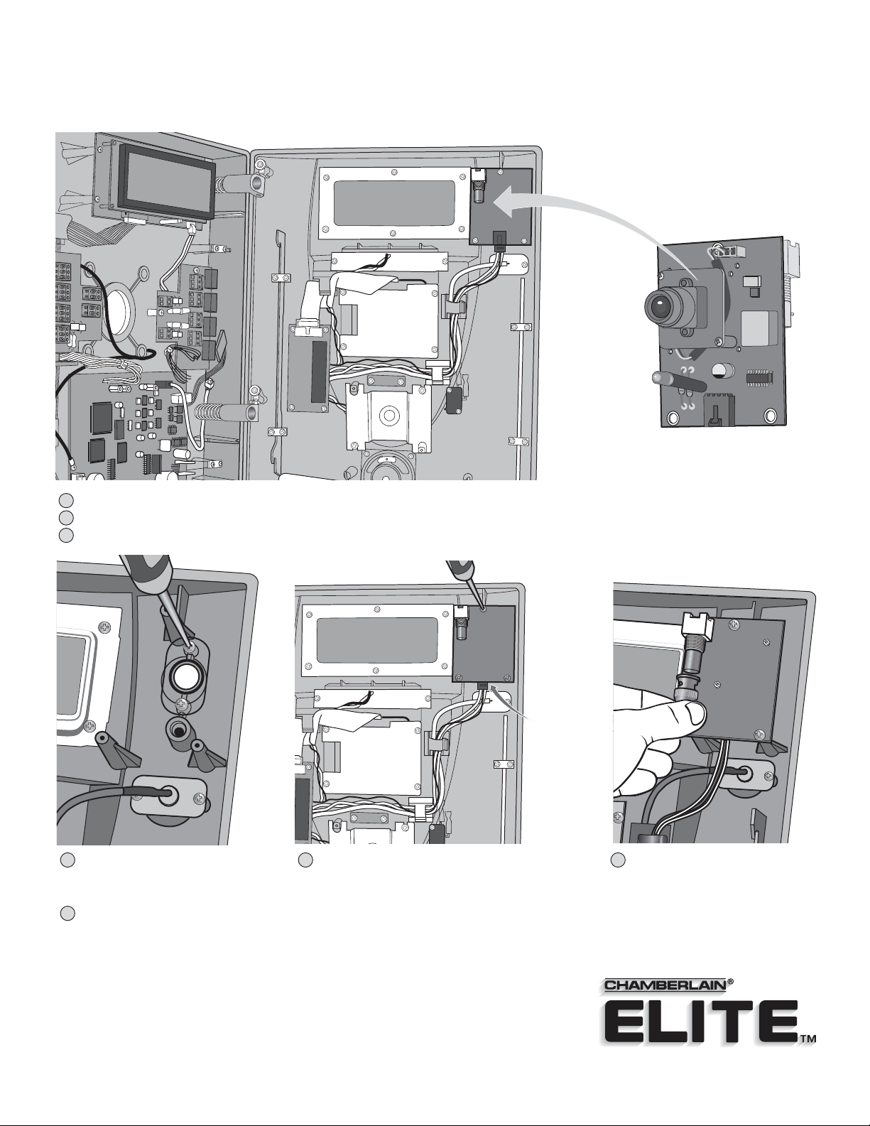
Camera Module
Replaces the LED Board.
1
Disconnect power to the unit!
2
Unlock and open the unit.
3
Unplug the wire harness from LED board, remove and discard LED board. (3 screws) Keep “O” ring from old board and place on new board.
LED
Board
Wire
Harness
Replace black plastic lens with the clear
4
lens. Keep rubber “O” ring in place.
7
Plug the other end of the coaxial cable into a monitor or home entertainment system.
Reconnect the power to the EL2000 and the camera picture will appear.
NOTE: If the EL2000 is connected to a home entertainment system, the home entertainment
system must be switched to video input.
Install the camera module (3 screws). Reconnect the
5 6
LED board wire harness to the camera module.
Feed coaxial cable (not provided)
through the conduit hole in the
back mounting plate of the EL2000.
Carefully connect a BNC coaxial
connector to the back of the
camera module. Close and lock
the unit.
B/W, Color and Low Lux Color Cameras
2
for the EL25 telephone entry/access control system
Model EL25BWCAMKT
Model EL25CCAMKT
Model EL25DVRCAMKT
Caution!
A static discharge can
DAMAGE circuit boards.
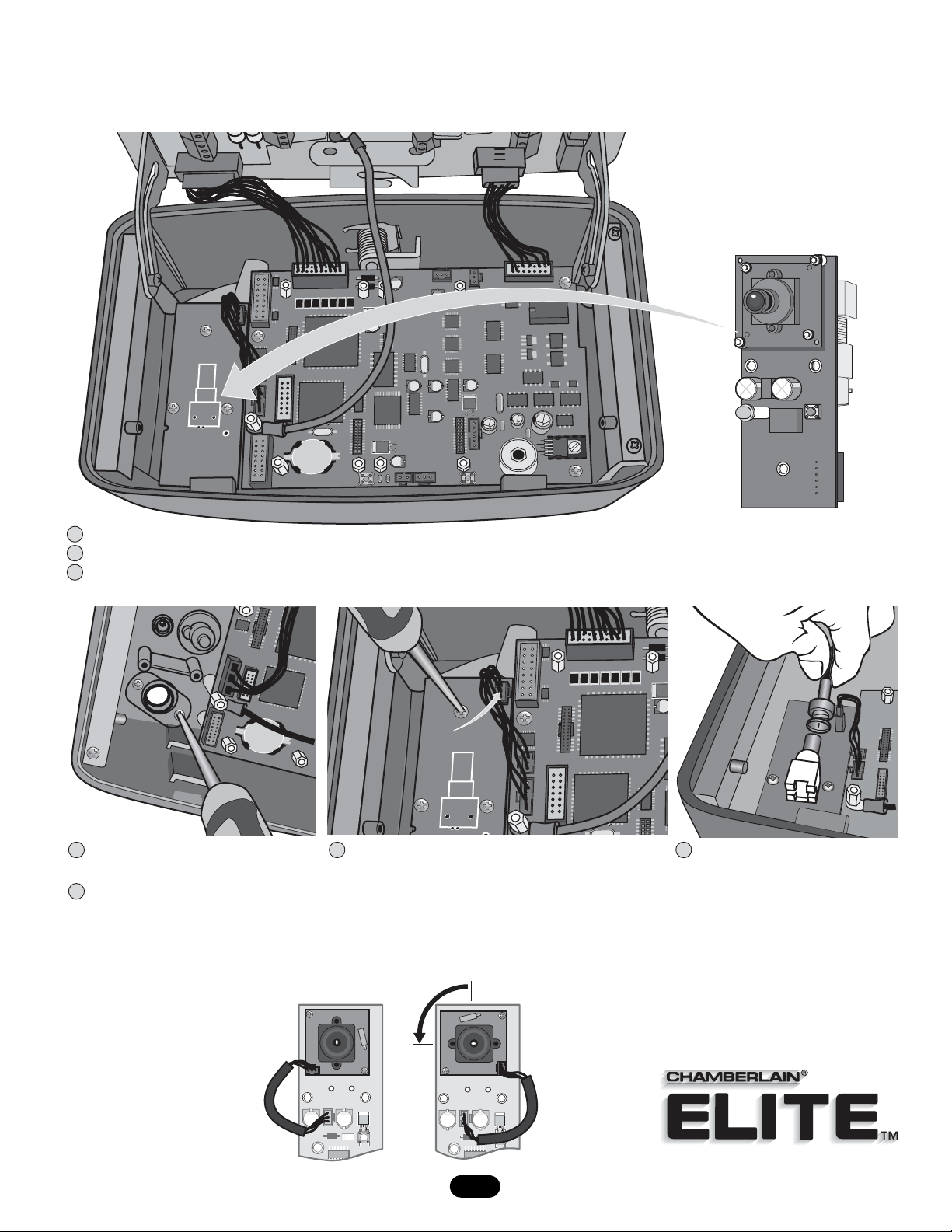
Call Button
LED
LED Board
Board
Board
+
1
Disconnect power to the unit!
2
Unlock and open the unit.
3
Unplug the wire harness from LED board, remove and discard call button board. (3 screws)
Keep “O” ring from old board and place on new board.
+
LED
Board
Wire
Harness
Replace black plastic lens with the clear
4
lens. Keep rubber “O” ring in place.
7
Plug the other end of the coaxial cable into a monitor or home entertainment system.
Install the camera module (3 screws). Reconnect the
5 6
LED board wire harness to the camera module.
Reconnect the power to the EL25 and the camera picture will appear.
NOTE: If the EL25 is connected to a home entertainment system, the home entertainment
system must be switched to video input.
Camera Module
Replaces the LED Board.
Feed coaxial cable (not provided)
through the conduit hole in the
back mounting plate of the EL25.
Carefully connect a BNC coaxial
connector to the back of the
camera module. Close and lock
the unit.
Vertically Mounted EL25s ONLY:
The camera lens board must be
repositioned 90 degrees
counterclockwise before the
above steps can be performed.
Note: Carefully remove the
2 mounting screws in a
secure flat area to avoid
losing the parts!
H2
100A
UD
H2
100A
UD
90˚
Repositioned camera lens board (Portrait) ready
for installation in a vertically mounted EL25.
H2
100A
UD
H2
100A
UD
 Loading...