

Page 1

CCTV CAMERA KIT
INSTALLATION INSTRUCTIONS
These instructions cover the installation of the black/white
& color CCTV Camera Kit in Sentex Crown Jewel and
Infinity systems equipped for CCTV.
WIRE DISTANCE SPECIFICATIONS
Power Wire Distance: Up to 100
Video Cable Distance: Up to 1000
length based on monitor with .25 volt p-p.
composite signal sensitivity)
PARTS SUPPLIED
Part Number Qty. Description
SN1600009
SN1600008
SN5300059 1 12V 20VA Transformer
SN5600036 1 Right-Angle BNC Connector
SN6001576 1 Installation Instructions
Camera Assy. (Color) OR
1
Camera Assy. (Black & White)
PARTS NOT SUPPLIED
AC/DC Power Wire: 18 AWG, 2 conductor cable
Video Wire: Single conductor 75 ohm RG-59U
coaxial cable (Belden #9240 or equiv.) with BNC
connectors (Amphenol #31-71008 or equiv.)
CCTV Monitor (or television with video input).
INSTALLATION NOTES
The CCTV interface board requires a dedicated
power supply.
The video signal is continuously available at J2
on the CCTV interface board.
Feet
Feet (max
INSTALLATION
1 Remove power to the unit.
2 Open front panel of telephone entry unit.
3 Pull power wires from power supply to unit.
4 Pull video cable from television or CCTV monitor
to unit.
5 Remove and discard four mounting plate screws
and mounting plate from front panel.
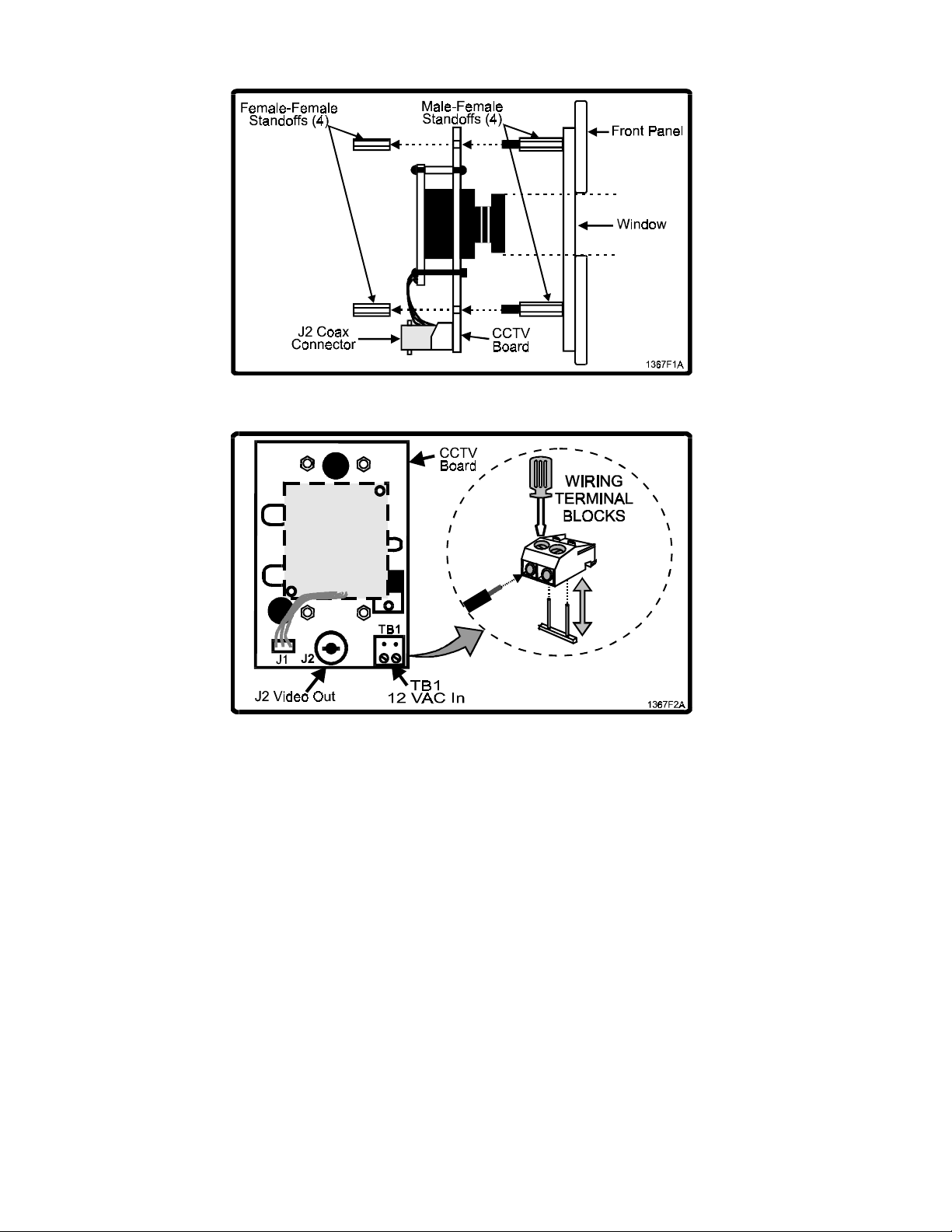
6 Remove and retain four female-female standoffs.
NOTE: Male-female standoffs remain in place.
7 Remove lens cap from CCTV lens.
8 Mount CCTV board on front panel male-female
standoffs with J2 coax connector facing the
bottom of unit. Make sure camera lens aligns
with window in front panel.
CAUTION: Use care with next step. Male-female
standoff studs will break if over-tightened.
9 Secure CCTV board to front panel using female-
female standoffs (previously removed). Carefully
snug with 3/16” nut driver.
10 Connect coaxial cable with BNC connector to J2
BNC connector on CCTV board.
11 Connect the power wire to terminal block TB1
(see Figure 2):
Lift blue terminal block off TB1 terminal pins.
Remove “head” and loosen screws.
Insert wire into opening on front and tighten
screw until wire is held firmly.
When both connections are made, plug
terminal block back onto pins.
Doc 6001576, Rev A
Page 2
Page 2 of 2
Figure 1: Mounting the CCTV Board
Figure 2: Power and Video Connections
TEST AND ADJUSTMENT
1 Plug in AC power supply.
2 Turn ON power to unit.
3 Plug coax cable into CCTV monitor or television.
4 Turn ON CCTV monitor or television. The CCTV picture will appear.
5 Close front panel.
Doc 6001576, Rev A
 Loading...