

Page 1
Lift-Master
The Professional Line
OWNERS MANUAL
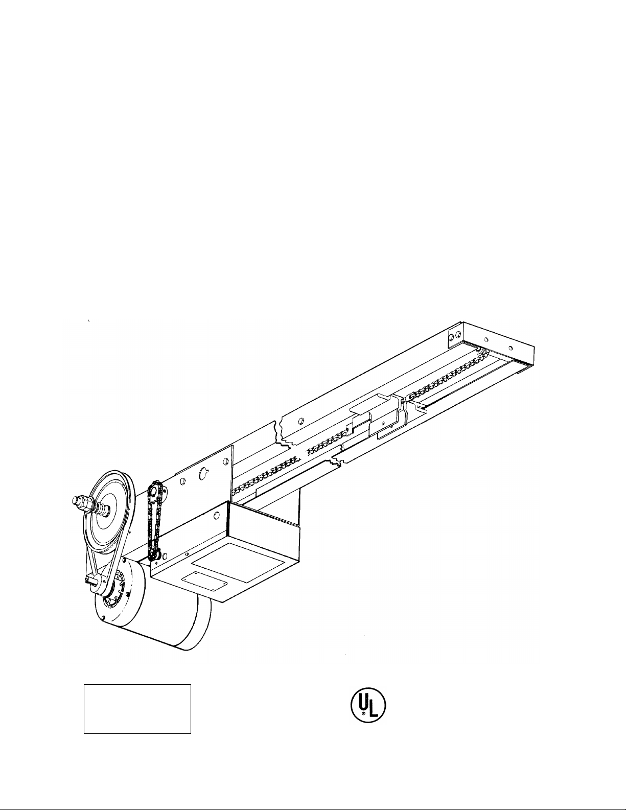
MODEL BT
BELT TROLLEY
The Chmaberlain Group, Inc.
A Unit of Duchossois Industries, Inc.
845 Larch Avenue, Elmhurst, Illinois 60126
SERIES B
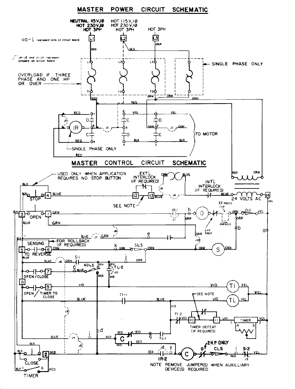
WIRING
TYPE
COMMERCIAL DOOR OPERATOR
LISTED
Page 2

VOLTAGE/PHASE
SINGLE
PH
JUMPERS
& RELAYS
JA X
JB X X
JC X X X X
JE X X
J1 X X X
J2 X X X
120V LR RELAY X
240V IR RELAY X
INLINE OVERLOAD X X
TIME CAPSULE*** X
* OPTIONAL ADJUSTABLE TIMER FUNCTION
AVAILABLE TO ACTIVATE WARNING SYSTEM
PRIOR TO AUTOMATIC DOOR CLOSING
(REQUIRES 115V POWER SOURCE IF
OPERATOR IS NOT 115 VOLT.)
** MOTORS AT THESE RATINGS ARE SUPPLIED
AS STANDARD WITH AN INTERNAL,
AUTOMATIC RESETTING OVERLOAD. (IN LINE
OVERLOADS ARE OPTIONAL)
X X
**
THREE
PH
X X
JUMPER CHART
JUMPERS,
RELAYS
SWITCHES &
TIMERS
J3
J4
J6
J7
J8
J9
J10
J11
SENSING LIMIT
AUX DEVICE
LIMIT
TIMER IMPULSE
RELAY
TIMER LATCHING
RELAY
TIMER
3 BUTTON
STATION
2 BUTTON
STATION
1 BUTTON
STATION
WIRING TYPES * * * *
B C D E B1 C1 D1 B2 C2 E2 S T ST TS STS
X X X X
X X X X X X X X
X X X X X X X
X X
X X X X X X X X X X X X X
X X X X X X X X
X X X
X X X X X X X X X
X X
X X X X X X X X X X X X
X X X X X X X X X X X
X X X X X X
X X X X
X X X X
X X X X
X X X X X X X X
X X X X
X X X
*** L5 SEC. DELAY TO OPEN TIME CAPSULE
ALLOWS LARGE DOORS TIME TO SETTLE
DOWN BEFORE REVERSING TO OPEN
POSITION.
NOTE: ELECTRIC EYES AND LOOP
DETECTORS ARE NOT TO BE USED AS
SENSING DEVICES TO STOP OR REVERSE
WHEN TS OR STS WIRING TYPES ARE USED.
OVERLOAD AND CAPACITOR VALUES
SINGLE PHASE THREE PHASE
OVERLOAD VALUES CAPACITOR VALUES OVERLOAD VALUES
115 VOLT
HP AMP PART
1/3
7
1/2 10 452433 5 452430 3781 15 452434 8 452432 3782
- - - - - - - -
3
- - - - - - - -
NO.
452431 3.5 452429 378-
230 VOLT CENTURY FRANKLIN 230 VOLT 460 VOLT
MFD/VAC PART
NO.
MFD/VAC PART
NO.
453212 386-
455/125
453212 386-
455/125
453212 431-
455/125
MOTOR REPLACEMENT
HP 1 PHASE 3 PHASE
AMP PART
NO.
453213 2.20** 453377 1.00** 453375
464/110
453213 2.60 453377 1.40 453375
464/110
453214 4.00 453378 1.95 453376
518/110
PART NUMBER
AMP PART NO.
6.20 453380 3.20 453378
10.50 458001 5.20 453380
AMP
PART
NO.
1/3 451347 451350
1/2 451348 451351
1 451349 451352
2 -------- 451353
Page 3

TYPE STATION NUMBER FUNCTION
B 3 Button 453365 Momentary contact to open, close and stop.
B1 3 Button 453639 Momentary contact to open, close and stop plus wiring for sensing
device to stop.
B2 3 Button 453642 Momentary contract to open, close and stop plus wiring for sensing
device to reverse and auxiliary devices to open and close with
override.
C 3 Button 453636 Momentary contact to open and stop with constant pressure to
close.
C1 3 Button 453640 Momentary contact to open and stop with constant pressure to close
and wiring for sensing device to stop.
C2 3 Button 453643 Momentary contact to open and stop with constant pressure to
close.
D 2 Button 453641 Constant pressure to open and close.
D1 2 Button 453641 Constant pressure to open and close with wiring for sensing device
to stop.
E 2 Button 453638 Momentary contact to open and constant pressure to close. Release
of close button will cause door to reverse (rollback feature).
E2 2 Button 453644 Momentary contact to open with open override and constant
pressure to close.
S 1 Button 453645 Momentary contact to open and close plus wiring for sensing device
to reverse, auxiliary devices to open and close, with open override.
T 3 Button 453646 Momentary contact to open, close and stop with open override and
timer to close. Open button may be connected to activate timer if
desired. Auxiliary controls may be connected to open and activate to
close or to open and close, without activating timer.
ST 1 Button 453647 “T” type wiring with single button instead of three button operation.
(See “S” type wiring.)
TS 3 Button 453648 momentary contact open, close and stop with open override and
timer to close. EVERY device that causes door to open will activate
timer to close including sensing device to reverse. Timer may be
deactivated until next opening signal is received by depressing stop
button after door has reached open position or permanently by use
of optional timer defeat switch. Photo-cell or loop detector not
recommended for use as a sensing device to reverse with this wiring
type.
STS 1 Button 453649 ‘TS” type wiring with single button instead of three button operation.
(See ‘S” type wiring.)
Notes: 1. External interlocks may be wired into all wiring types.
2. Auxiliary devices are any devices that have only one set of contacts.
Examples are: photo-cell, loop detector, pneumatic or electric treadles,
residential radio controls, one button stations, pull cords\, etc.
3. open override means that the door may be reversed while closing by
activating an opening device without the need to use the step button first.
Page 4
Page 5

Page 6

MOTOR WIRING DIAGRAMS
1 PHASE
114A1039 1987, The Chamberlain Group, Inc
Rights Reserved Printed in Mexico
Page 7

CONTROL CONNECTION DIAGRAM
Page 8

Page 9

CHART A
TRACK
LENGTH
11’ 453840 350112 451868
13’ 453841 350113 451869
15’ 453842 350114 451870
17’ 453843 350115 451871
19’ 453844 350116 451872
21’ 453845 350117 451873
23’ 453846 350118 451874
25’ 453847 451847 451875
27’ 453848 451858 451876
NOTE: * ITEM NOT SHOWN ON DRAWING. SEE INSTALLATION
INSTRUCTIONS.
** ITEMS TO BE ORDERED AS ASSEMBLIES ONLY. *** SEE CHART
“A”. PART NUMBERS VARY WITH TRACK LENGTH.
ITEM PT.NO. DESCRIPTION QUANTITY
1 451915 Base, Frame 1 1 1 1 1 1 1 1 1 1 1
2 452219 Bushing, 3/4” Flanged Key 4 4 4 4 4 4 4 4 4 4 4
3 450572 Sprocket, 43-B-10 - 3/4” Bore 2 2 2 2 2 2 2 2 2 2 2
4 450584 Sprocket, 43-B-30 - 3/4” Bore 1 1 1 1 1 1 1 1 1 1 1
5 452032 Setscrew, Socket Hd. 5/16”-18x1/4” <---------- 13 ---------->
6 450168 Shaft, Drive T & J 3/4” 1 1 1 1 1 1 1 1 1 1 1
7 450421 Key, Woodruff - 3/16” 2 2 2 2 2 2 2 2 2 2 2
8 230702 Bolt, Hex Head 3/8-16x3/4” QUANTITY VARIES
9 230301 Nut, Hex 3/8-16 WITH
10 230601 Washer, Lock - 3/8” TRACK LENGTH
11 230707 Bolt, Hex Head 1/4-20x3/4” 4 4 4 4 4 4 4 4 4 4 4
12 453105 Collar, Sgaft 3/4” 3 3 3 3 3 3 3 3 3 3 3
13 451855 Chain, Roller #65, 43 Pitch w/Link 1 1 1 1 1 1 1 1 1 1 1
14 451854 Chain, Roller #65, 33 Pitch w/Link 1 1 1 1 1 1 1 1 1 1 1
15 453406 Trolley Slide Assembly 1 1 1 1 1 1 1 1 1 1 1
16** 452988 Idler Shft. Assy. 1/3 & 1/2 HP Motors 1 1 1 1 1 1 1
17 453823 Wall Bracket 1 1 1 1 1 1 1 1 1 1 1
18 453822 Track Spacer QTY. VARIES W/TRACK LENGTH
19 450572 Sprocket, 43-B-10 1/3 & 1/2 HP Mtrs 1 1 1 1 1 1 1
20** 452957 Pulley Shaft Assembly 1 1 1 1 1 1 1 1 1 1 1
21 451106 Motor Pulley - 5/8” Bore 1 1 1 1 1 1 1 1 1 1 1
22 451415 ‘V’ Belt 31” 1 1 1 1 1 1 1 1 1 1 1
23 230302 Nut, Hex 5/16” 4 4 4 4 4 4 4 4 4 4 4
24 230604 Washer, Lock 5/16” 4 4 4 4 4 4 4 4 4 4 4
25 230501 Washer, Flat - 5/16” 8 8 8 8 8 8 8 8 8 8 8
26 230719 Bolt, Hex Head 5/16-18x3/4” 4 4 4 4 4 4 4 4 4 4 4
27 230303 Nut, Hex 1/4-20 4 4 4 4 4 4 4 4 4 4 4
28 450420 Key, 3/16”x1-1/4” Long 2 2 2 2 2 2 2 2 2 2 2
29 452033 Screw, Sheet Metal #6x3/8” 2 2 2 2 2 2 2 2 2 2 2
30 451276 Cover, Electrical Box 1 1 1 1 1 1 1 1 1 1 1
31 *** Chain Roller #48 - 1/3 & 1/2 HP Mtrs 1 1 1 1 1 1 1
32 *** Track Angle 2 2 2 2 2 2 2 2 2 2 2
33 Assembly, Electrical Box See Detail
34 451347 Motor, 1/3HP - 115/230V 1 Phase 1
TRACK
PART NO.
#48 CHAIN
PART NO.
#41 CHAIN
PART NO.
453435 Assembly, Idler Shaft 1 HP Motors 1 1 1 1
450519 Sprocket, 41-B-10 1 HP Motors 1 1 1 1
*** Chain Roller #41 - 1 HP Motors 1 1 1 1
451350 Motor, 1/3 HP - 230/460V 3 Phase 1 1
451348 Motor, 1/2 HP - 115/230V 1 Phase 1 1
451351 Motor, 1/2 HP - 230/460V 3 Phase 1 1
451349 Motor, 1 HP - 115/230V 1 Phase 1 1
451352 Motor, 1 HP - 230/460V 3 Phase 1 1
1
1
1
1
1
1
/
/
/
/
3
3
3
/
2
2
1
/
/
1
1
1
2
2
1
O
P
H
H
H
H
H
H
H
H
H
H
E
P
P
P
P
P
P
P
P
P
H
P
P
R
A
1
2
2
1
2
2
4
1
2
2
T
1
3
3
1
3
3
6
1
O
5
0
0
5
0
0
R
V
V
V
V
V
1
1
3
1
1
P
P
P
P
H
H
A
S
E
H
A
A
S
S
E
E
P
H
H
A
A
S
S
E
E
0
V
V
3
3
P
P
H
H
A
A
S
S
E
E
3
5
0
V
V
1
1
P
P
H
H
A
A
S
S
E
E
4
3
6
0
0
V
V
3
3
P
P
H
H
A
A
S
S
E
E
36 * 451514 Arm, Curved 1 1 1 1 1 1 1 1 1 1 1
37 * 450829 Door Bracket 1 1 1 1 1 1 1 1 1 1 1
38 * 453405 Release Arm Assembly 1 1 1 1 1 1 1 1 1 1 1
39 * 230730 Bolt, Hex head 516-18x1-1/2 1 1 1 1 1 1 1 1 1 1 1
40 * 452076 Nut, Lock - Hex 5/16-18 1 1 1 1 1 1 1 1 1 1 1
41 * 452076 Bolt, Hex Head 5/16-18x1” 3 3 3 3 3 3 3 3 3 3 3
42 * 230302 Nut, Hex 5/16-18 4 4 4 4 4 4 4 4 4 4 4
43 * 230604 Washer, Lock 5/16” 2 2 2 2 2 2 2 2 2 2 2
44 * 450236 Clamp, Cable - 90º-3/8”Tooth 1 1 1 1 1 1 1 1 1 1 1
45 * 453123 Lock Washer 1/4” Ewxternal Tooth 8 8 8 8 8 8 8 8 8 8 8
46 * 453124 Lock Washer 5/16” External Tooth 4 4 4 4 4 4 4 4 4 4 4
Page 10

10
Page 11

B
T
E
L
E
C
T
R
I
C
A
L
B
O
X
ITEM PT.NO. DESCRIPTION QUANTITY
A 453020 P.C. Board, Option - Commercial 1 1 1 1 1 1 1 1 1 1 1 1
B 453021 Contractor, S/D 1 1 1 1 1 1 1 1 1 1 1 1
C 453336 Switch, Limit - Open, Wired 1 1 1 1 1 1 1 1 1 1 1 1
D 453339 Switch Limit - Closed, Wired 1 1 1 1 1 1 1 1 1 1 1 1
E 453335 Assembly, Motor Cable 1 1 1 1 1 1 1 1 1 1 1 1
F 451278 Box, Electrical - P.C.B. 1 1 1 1 1 1 1 1 1 1 1 1
G 453115 Standoff 4 4 4 4 4 4 4 4 4 4 4 4
H 452077 Nut Lock 8-32 2 2 2 2 2 2 2 2 2 2 2 2
I 450587 Nut Limit - Plastic, 1/2x20 2 2 2 2 2 2 2 2 2 2 2 2
J 452078 Screw, Sheet Metal - Grn. (Gnd) 1 1 1 1 1 1 1 1 1 1 1 1
K 453231 230V I.R. Relay 1 1 1
453232 115V I.R. Relay 1 1 1
L 450252 Wire Ties 3/32” 3 3 3 3 3 3 3 3 3 3 3 3
M 450229 Terminal, Double Male 1/4” 5 5 5 5 5 5 5 5 5 5 5 5
N 452094 Screw, Sheet Metal 12-24x1/2” 2 2 2 2 2 2 2 2 2 2 2 2
O 230612 Washer, Lock #4 Internal Tooth 8 8 8 8 8 8 8 8 8 8 8 8
P 453332 Assy. Wire 22 GA. Green (Gnd) 1 1 1 1 1 1 1 1 1 1 1 1
Q 452036 Cable Clamp 1 1 1 1 1 1 1 1 1 1 1 1
R 453354 Overload, 3.5A 1 Phase 1
453355 Overload, 5.0A 1 Phase 1
453356 Overload, 7.0A 1 Phase 1
453357 Overload, 8.0A 1 Phase 1
453358 Overload, 10.0A 1 Phase 1
453359 Overload, 15.0A 1 Phase 1
453376 Assy., Overload, 195A 3 Phase 1
453378 Assy., Overload, 4.0A 3 Phase 1
* * * *
1
1
1
1
1
/
/
/
3
3
H
H
P
P
1
2
1
3
5
0
V
V
1
1
P
P
H
H
A
A
S
S
E
E
/
3
3
H
H
P
P
2
4
3
6
0
0
V
V
3
3
P
P
H
H
A
A
S
S
E
E
1
/
/
2
2
H
H
P
P
1
2
1
3
5
0
V
V
1
1
P
P
H
H
A
A
S
S
E
E
1
1
/
/
1
1
2
2
H
H
P
2
3
0
V
3
P
H
A
S
E
H
P
P
4
1
6
1
0
5
V
V
3
1
P
P
H
H
A
A
S
S
E
E
1
H
H
P
P
2
2
3
3
0
0
V
V
1
3
P
P
H
H
A
A
S
S
E
E
1
H
P
4
6
0
V
3
P
H
A
S
E
Page 12

B
T
E
L
E
C
T
R
I
C
A
L
B
O
X
ITEM PT.NO. DESCRIPTION QUANTITY
S 452048 Screw, Rd. 8-32x3/8” 2 2 2 2 2 2 2 2 2 2 2 2
T 453207 Assembly, Transformer 110V 1 1 1
453208 Assembly, Transformer 230V 1 1 1 1 1 1
U 452033 Screw, Sheet Metal #6x3/8” 2 2
V 453247 Spring, I.R. Relay 1 1 1 1 1 1
W 453037 Power Terminal Strip Guard 1 1 1 1 1 1 1 1 1 1 1 1
X 230615 Lock Washer #8 External Tooth 1 1 1 1 1 1 1 1 1 1 1 1
LIMIT SWITCH ASSEMBLY
* * * *
1
1
1
1
1
/
/
/
3
3
H
H
P
P
1
2
1
3
5
0
V
V
1
1
P
P
H
H
A
A
S
S
E
E
/
3
3
H
H
P
P
2
4
3
6
0
0
V
V
3
3
P
P
H
H
A
A
S
S
E
E
1
/
/
2
2
H
H
P
P
1
2
1
3
5
0
V
V
1
1
P
P
H
H
A
A
S
S
E
E
1
1
/
/
1
1
2
2
H
H
P
2
3
0
V
3
P
H
A
S
E
H
P
P
4
1
6
1
0
5
V
V
3
1
P
P
H
H
A
A
S
S
E
E
1
H
H
P
P
2
2
3
3
0
0
V
V
1
3
P
P
H
H
A
A
S
S
E
E
1
H
P
4
6
0
V
3
P
H
A
S
E
ITEM PT. NO. DESCRIPTION QUANTITY
100 171A335 Hex. Hd. Mach. Scr. #4-40x5/8” 4 4 4 4 4 4 4 4 4 4 4 4
101 450347 Spacer, Limit Switch 4 4 4 4 4 4 4 4 4 4 4 4
102 171A336 Hex Hd. Mach Scr. #4-40x5/16” 2 2 2 2 2 2 2 2 2 2 2 2
103 171A275 Hed Hd. Mach Scr. #8-32x3/4” 2 2 2 2 2 2 2 2 2 2 2 2
104 177A113 Spring Compression 2 2 2 2 2 2 2 2 2 2 2 2
105 450353 Bracket, L/S Mounting 1 1 1 1 1 1 1 1 1 1 1 1
106 450349 Retaining Ring 1 1 1 1 1 1 1 1 1 1 1 1
107 450350 Bearing, Flange 2 2 2 2 2 2 2 2 2 2 2 2
108 450179 Shaft Limit 1 1 1 1 1 1 1 1 1 1 1 1
109 450348 Sprocket, Limit Switch 1 1 1 1 1 1 1 1 1 1 1 1
110 171A338 Scr. Skt. Hd. Set #10-21x1/4 1 1 1 1 1 1 1 1 1 1 1 1
111 450352 Retainer, Travel Nut 1 1 1 1 1 1 1 1 1 1 1 1
112 171A337 Scr. Hex Hd. Mach #8-32x1/2” 4 4 4 4 4 4 4 4 4 4 4 4
113 452026 Washer, Split Lock #8 4 4 4 4 4 4 4 4 4 4 4 4
114 452003 Nut, Hex #8-32 4 4 4 4 4 4 4 4 4 4 4 4
* MOTORS AT THESE RATINGS ARE SUPPLIED AS STANDARD WITH AN INTERNAL AUTOMATIC
RESETTING OVERLOAD. (IN LINE OVERLOADS ARE OPTIONAL.)
 Loading...