

Page 1

I N S T A L L A T I O N M A N U A L
I N S T A L L A T I O N M A N U A L
INTENDED FOR PROFESSIONAL
INSTALLATION ONLY
MODEL MT5011E/BMT5011E
MEDIUM DUTY DOOR OPERATOR
Now with
Built in
Radio Receiver
INTENDED FOR PROFESSIONAL
INSTALLATION ONLY
Visit www.LiftMaster.com to locate a professional installing dealer in your area.
2 YEAR WARRANTY
Serial #
(located on electrical box)
Installation Date
A SAFETY DEVICE IS HIGHLY RECOMMENDED.
Radio Receiver
Built on Board
315MHz
NOT FOR RESIDENTIAL USE
Page 2

WARNINGWARNING
WARNING
WARNING
WARNINGWARNING
WARNING
CAUTIONCAUTION
WARNING
WARNING
TABLE OF CONTENTS
SAFETY INFORMATION . . . . . . . . . . . . . . . . . . . . . . . . . . . . . . . . . . . . . . . . . . . . . . . . . . . . . . . . . . . . . . . . . . . . . . . . . .2
APPLICATION . . . . . . . . . . . . . . . . . . . . . . . . . . . . . . . . . . . . . . . . . . . . . . . . . . . . . . . . . . . . . . . . . . . . . . . . . . . . . . . . . 3
OPERATOR DIMENSIONS . . . . . . . . . . . . . . . . . . . . . . . . . . . . . . . . . . . . . . . . . . . . . . . . . . . . . . . . . . . . . . . . . . . . . . . .4
OPERATOR SPECIFICATIONS . . . . . . . . . . . . . . . . . . . . . . . . . . . . . . . . . . . . . . . . . . . . . . . . . . . . . . . . . . . . . . . . . . . .4
CARTON INVENTORY. . . . . . . . . . . . . . . . . . . . . . . . . . . . . . . . . . . . . . . . . . . . . . . . . . . . . . . . . . . . . . . . . . . . . . . . . . . 5
PREPARATION . . . . . . . . . . . . . . . . . . . . . . . . . . . . . . . . . . . . . . . . . . . . . . . . . . . . . . . . . . . . . . . . . . . . . . . . . . . . . . . . 5
ASSEMBLY . . . . . . . . . . . . . . . . . . . . . . . . . . . . . . . . . . . . . . . . . . . . . . . . . . . . . . . . . . . . . . . . . . . . . . . . . . . . . . . . . 6-8
TYPICAL INSTALLATION . . . . . . . . . . . . . . . . . . . . . . . . . . . . . . . . . . . . . . . . . . . . . . . . . . . . . . . . . . . . . . . . . . . . . .9-14
ADJUSTMENT . . . . . . . . . . . . . . . . . . . . . . . . . . . . . . . . . . . . . . . . . . . . . . . . . . . . . . . . . . . . . . . . . . . . . . . . . . . . . .14-15
OPTIONAL SAFETY DEVICE CONFIGURATIONS . . . . . . . . . . . . . . . . . . . . . . . . . . . . . . . . . . . . . . . . . . . . . . . . . .15-16
LOGIC BOARD LAYOUT . . . . . . . . . . . . . . . . . . . . . . . . . . . . . . . . . . . . . . . . . . . . . . . . . . . . . . . . . . . . . . . . . . . . . . . . . 17
BASIC PROGRAMMING . . . . . . . . . . . . . . . . . . . . . . . . . . . . . . . . . . . . . . . . . . . . . . . . . . . . . . . . . . . . . . . . . . . . 18-20
TESTING . . . . . . . . . . . . . . . . . . . . . . . . . . . . . . . . . . . . . . . . . . . . . . . . . . . . . . . . . . . . . . . . . . . . . . . . . . . . . . . . . . . . .21
MANUAL DISCONNECT . . . . . . . . . . . . . . . . . . . . . . . . . . . . . . . . . . . . . . . . . . . . . . . . . . . . . . . . . . . . . . . . . . . . . . . . .21
TROUBLESHOOTING . . . . . . . . . . . . . . . . . . . . . . . . . . . . . . . . . . . . . . . . . . . . . . . . . . . . . . . . . . . . . . . . . . . . . . . 22-23
DIAGRAM . . . . . . . . . . . . . . . . . . . . . . . . . . . . . . . . . . . . . . . . . . . . . . . . . . . . . . . . . . . . . . . . . . . . . . . . . . . . . . . . . . . 23
REPAIR PARTS . . . . . . . . . . . . . . . . . . . . . . . . . . . . . . . . . . . . . . . . . . . . . . . . . . . . . . . . . . . . . . . . . . . . . . . . . . . . 24-26
ACCESSORIES . . . . . . . . . . . . . . . . . . . . . . . . . . . . . . . . . . . . . . . . . . . . . . . . . . . . . . . . . . . . . . . . . . . . . . . . . . . . . . . .27
CONTROL CONNECTIONS . . . . . . . . . . . . . . . . . . . . . . . . . . . . . . . . . . . . . . . . . . . . . . . . . . . . . . . . . . . . . BACK COVER
SAFETY INFORMATION
IMPORTANT NOTES:
Mechanical
Electrical
When you see these Safety Symbols and Signal Words on the
following pages, they will alert you to the possibility of serious
injury or death if you do not comply with the warnings that
accompany them. The hazard may come from something
mechanical or from electric shock. Read the warnings carefully.
• BEFORE attempting to install, operate or maintain the operator,
you must read and fully understand this manual and follow all
safety instructions.
• DO NOT attempt repair or service of your commercial door and
gate operator unless you are an Authorized Service Technician.
When you see this Signal Word on the following pages, it will
alert you to the possibility of damage to your door and/or the
door operator if you do not comply with the cautionary
statements that accompany it. Read them carefully.
2
Page 3
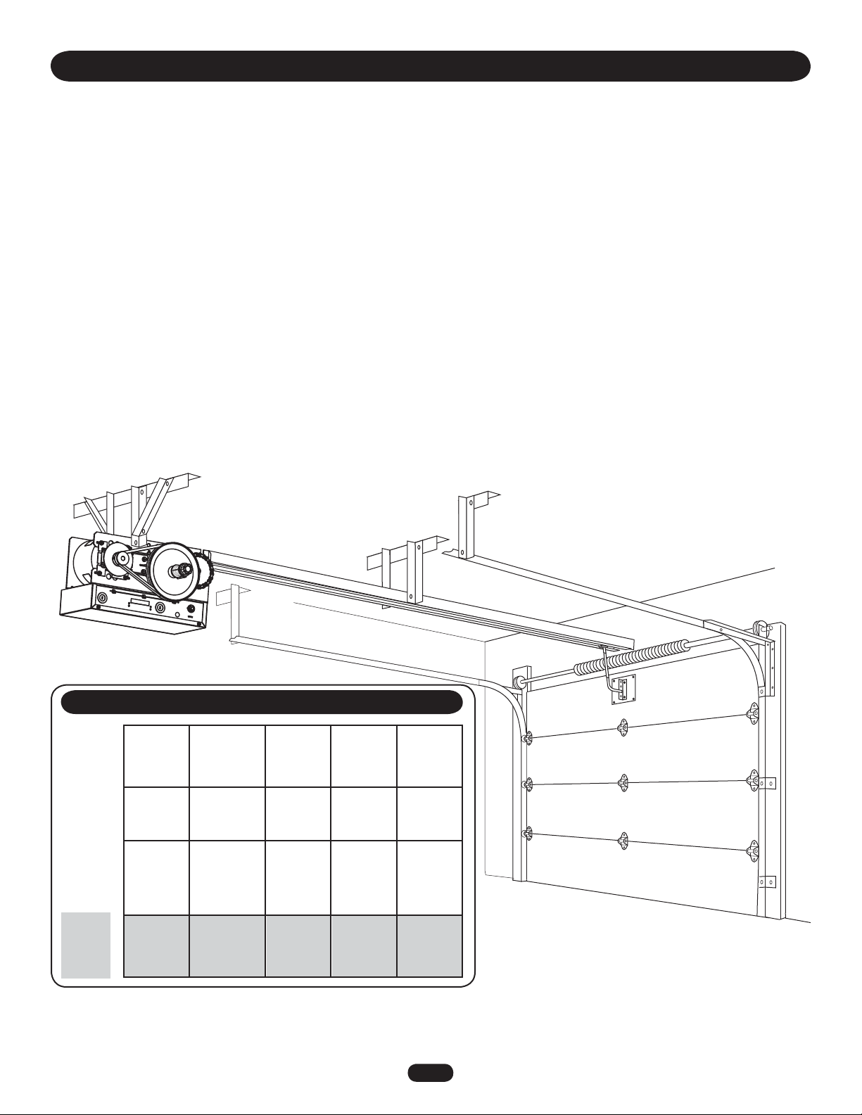
APPLICATION
INTRODUCTION
This Medium Duty Commercial Door Operator includes a number of features that will provide years of reliable and safe operation.
Features:
• Supports both monitored and non-monitored safety devices: Safety devices detect obstructions in the door's path and
automatically reverse a closing door. Safety devices are highly recommended by the manufacturer.
• Radio receiver: A factory installed radio receiver allows remote controls, keyless entries and other remote command devices to be
programmed to the operator.
• Timer To Close: The Timer To Close feature allows the door to automatically close after a preset time (only available with B2
wiring and a monitored safety device).
• Wiring Types: The functionality of the operator is based on the wiring type. The operator is shipped from the factory in standard
C2 wiring type (factory default). Some wiring types will require an optional safety device. Refer to Basic Programming Section for
descriptions of wiring types, requirements and programming.
MAXIMUM DOOR AREA AND MAXIMUM DOOR HEIGHT 14'
24 ga.
---
Fiberglass
--- ---
STANDARD SECTIONAL
310 260 225 150 100
FEET
SQUARE
22 ga.
Steel
Aluminum
Doors
20 ga.
Steel
Wood
Doors
24 ga.
Steel
Insulated
16 ga.
Steel
--- ---
20 ga.
Steel
Insulated
---
16 ga.
Steel
Insulated
NOTE: Actual track length will exceed door height by 2'.
3
Page 4
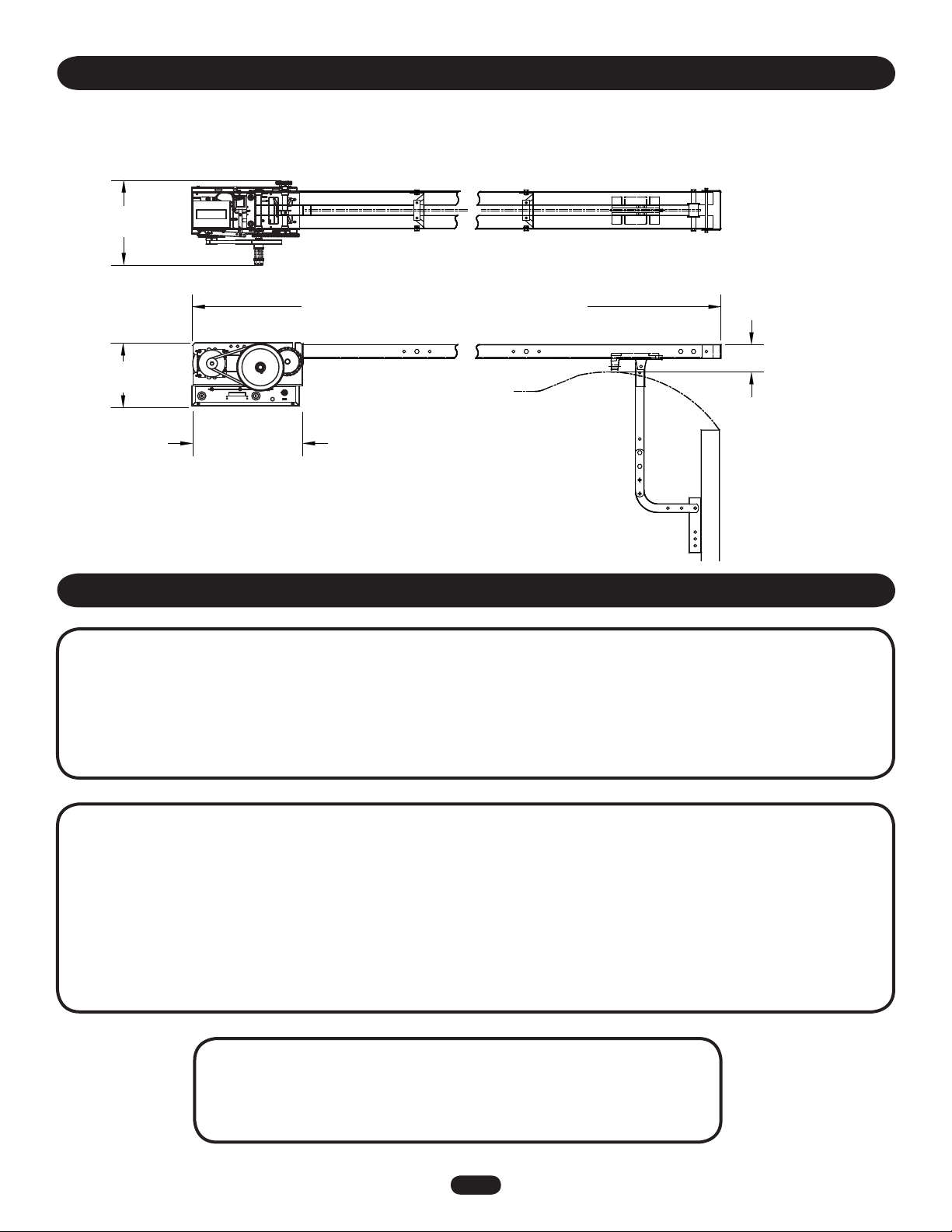
OPERATOR DIMENSIONS
WEIGHTS AND DIMENSIONS
HANGING WEIGHT:80-110 LBS. (36.29-49.9 kg) (Including Track)
12-1/2"
(31.75 cm)
Door Height Plus 4 feet (1.22 m) (minimum)
9-1/2"
(24.13 cm)
16-3/16"
(41.12 cm)
Path Of Highest Point On
Door
4"
(10.16 cm)
OPERATOR SPECIFICATIONS
MOTOR
TYPE: . . . . . . . . . . . . . . . . . . . . . . . . . . . . . . . . . . . Limited duty
HORSEPOWER: . . . . . . . . . . . . . . . . . . . . . . . . 1/2 Horsepower
VOLTAGE: . . . . . . . . . . . . . . . . . . . . 115Vac, Single Phase, 60Hz
FULL LOAD AMPS:. . . . . . . . . . . . . . . . . . . . . . . . . . . 6.0 Amps
MECHANICAL
DOOR SPEED:. . . . . . . . . . . . . . . . . . . . 12" (30.48 cm) / second
OUTPUT FORCE:. . . . . . . . . . . . . . . . . . . . . . . . . 125 ft. lbs/ sec.
BRAKE (BMT ONLY): . . . . . . . . . . Solenoid actuated disc brake
LIMIT ADJUST:. . . . . .Fully adjustable up to 14' door maximum
DUTY: . . . . . . . . . . . . . . . . . . . . . .12 Cycles per hour maximum
50 Cycles per day maximum
BEARINGS: . . . . . . . . . . . . . . . . . . . . . . . . . . . Maintenance Free
FINISH: . . . . . . . . . . . Powder coated, Corrosion Resistant Steel
ELECTRICAL
OPERATOR VOLTAGE: . . . . . . . . . 115 Vac, Single Phase, 60 Hz
WIRING TYPE: . . . . . . . C2 Standard B2 configurable (see Basic
Programming section)
CONTROL WIRING: . . . . . . . . . . . . . . . . . . . . . . . . . .16-22 AWG
SAFETY
DISCONNECT . . . . . . . . . . . . . . . . . . Quick disconnect door arm
for emergency manual door operation.
ENTRAPMENT PROTECTION: . . . . Supports both monitored and
non-monitored safety devices including LiftMaster CPS
photo-eyes and industry standard sensing edges.
ENVIRONMENTAL
LOCATION: . . . . . . . . . . . . . . . . . . . . . . . . . . . . . . . . . . . . . . . Indoor, dry location
OPERATING TEMPERATURE: . . . . . . . . . . . . . . . -4˚ F to +122˚F (-20C˚ to + 50˚C)
4
Page 5

CARTON INVENTORY
^
^
OPEN
CLOSE
O
STOP
WARNINGWARNING
WARNING
Before beginning your installation check that all components
were provided.
15
1
14
8
4
9
3
7
13
2
12
11
ITEM DESCRIPTION QTY
1 Operator 1
2 Track (left & right)
Door height plus 2' 2
3 Track Spacers 2
4 Front Idler 1
5 Trolley 1
6 Take-up Bolt 1
7 Chain 1
8 Master Links 2
9 Header Bracket 1
10 Header Pivot Shaft 1
11 Curved Door Arm 1
12 Straight Arm 1
13 Door Bracket 1
10
14 3-Button Station 1
15 Warning Sign 2
NOT SHOWN
Installation Manual 1
Quickstart Guide 1
User’s Guide 1
Caution Label 1
Installation Hardware Bag 1
6
Complete with: Bolts 3/8"-16 x 3/4 " (10),
Flanged Hex Nuts 3/8"-16 (14), Bolt 3/8"-16 x 1
(3), Lockwashers 3/8" (3), Cotter Pins (2) and
Carriage Bolts (2)
NOTE: Depending on door height, the quantity of track
5
spacers and hardware may vary.
NOTE: The tracks are shipped separately. Actual track length
will exceed door height by 2'. Example: The track for
12' door will be 14'.
PREPARATION
PREPARING YOUR DOOR
The manufacturer recommends 3' (91.4 cm) of clearance around
the operator for serviceability. Before you begin:
• Disable locks.
• Remove any ropes connected to door.
• Before the operator is installed, be sure the door has been
properly aligned and is working smoothly. Although each
installation will vary due to particular building characteristics,
refer to the following general procedures to install the operator.
To prevent possible SERIOUS INJURY or DEATH:
• DO NOT connect electric power until instructed to do so.
• If the door lock needs to remain functional, install an
interlock switch.
• ALWAYS call a trained professional door serviceman if door
binds, sticks or is out of balance. An unbalanced door may
not reverse when required.
• NEVER try to loosen, move or adjust doors, door springs,
cables, pulleys, brackets or their hardware, ALL of which are
under extreme tension and can cause SERIOUS personal
INJURY.
• Disable ALL locks and remove ALL ropes connected to door
BEFORE installing and operating door operator to avoid
entanglement.
5
Page 6
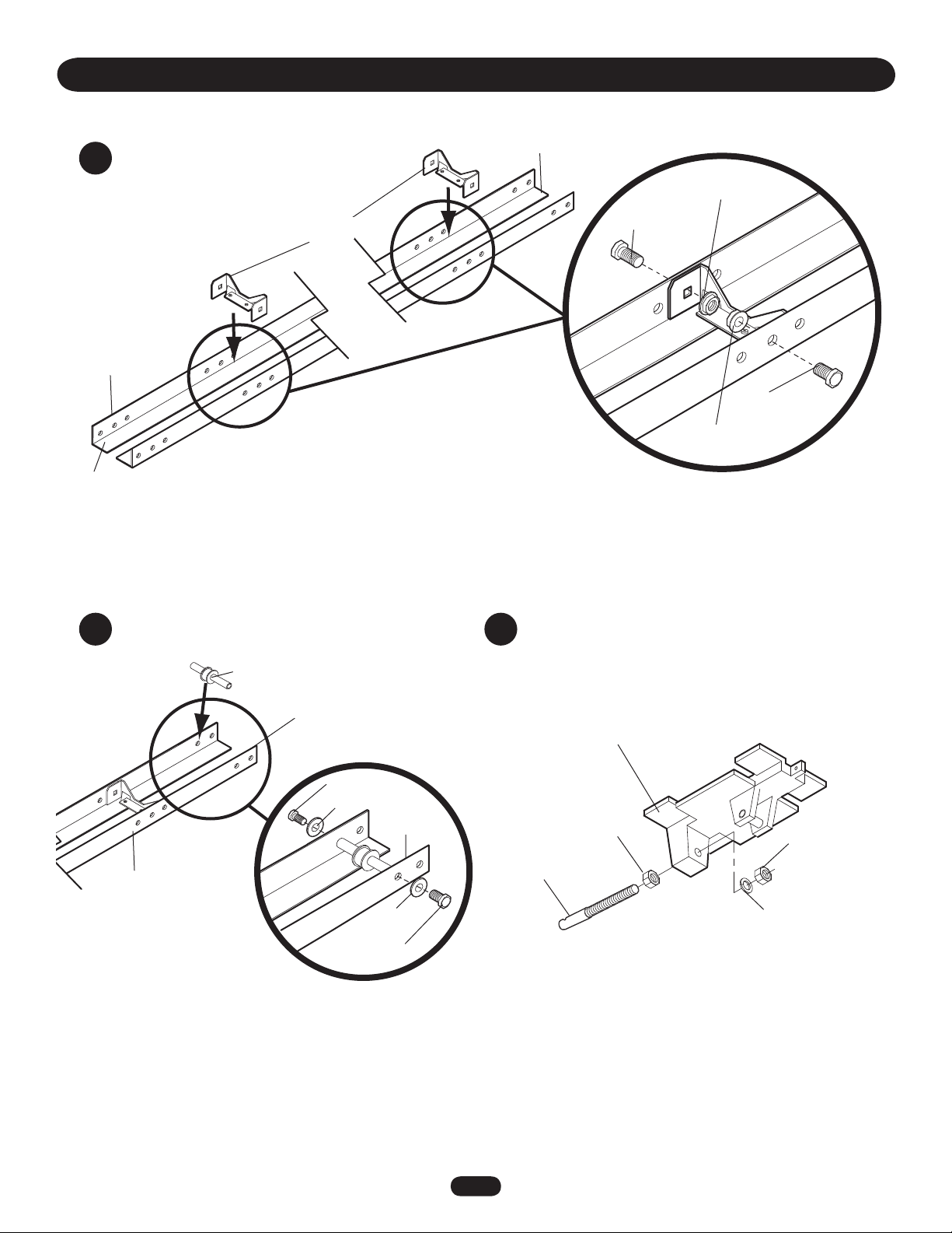
1
Track
Operator End
Install track spacers
Position the track spacers evenly
over the length of the track using
the pre-punched holes. For doors
up to 12' use 2 track spacers, for
14' doors use 3 spacers.
Track
Spacers
ASSEMBLY
Header End
Flange
Hex Nut
Bolt
3/8" - 16 x 3/4"
Bolt
3/8" - 16 x 3/4"
Flange
Hex Nut
Install front idler Assemble trolley
2 3
Front Idler
Header End
Bolt 3/8" -16 x 1"
Lock Washer
Header End
Track
Lock
Washer
Bolt 3/8" -16 x 1"
Take-Up Bolt
Trolley
Flange Nut
3/8" - 16
Flange Nut
3/8" - 16
Lock Washer
6
Page 7

Slide trolley onto the track
4
ASSEMBLY
Attach track to operator
5
Trolley
Track
Operator
End
Operator End
Trolley
Track
Bolt
3/8" - 16 x 3/4"
Operator
End
Flange Hex Nut
Track
Bolt
3/8" - 16 x 3/4"
Flange
Hex Nut
Header
End
Bolt
3/8" - 16 x 3/4"
Flange Hex
Nut
Bolt
3/8" - 16 x 3/4"
Operator
7
Page 8

Install chain
6
ASSEMBLY
Trolley
Attach chain
to front of
trolley
Chain
Master Link
Track
Front Idler
Chain
Run chain around
track in the direction
indicated
Wrap chain
around front
idler
Slide trolley 2" away from front idler
2"
Operator
Wrap chain
around drive
sprocket
Drive
Sprocket
Bottom of
Track
Adjust the
chain by
tightening the
inner nut
Chain
3"
Chain
Attach chain
to back of
trolley
Inner Nut
Master Link
Trolley
Bottom of
Track
More
than 3"
Chain
8
Page 9
TYPICAL INSTALLATION
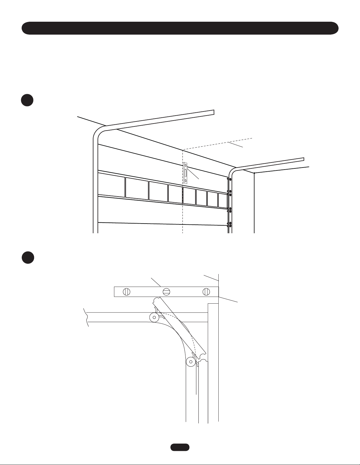
DETERMINE HEADER BRACKET MOUNTING LOCATION
The trolley operator is generally mounted over the center of the door. However, off center
mounting may be required due to interfering structures or location of door stile / top section
support. Typically, the operator may be mounted up to 24" (60.96 cm) off center on torsion
spring doors. Extension springs require center mounting.
Mark the center of the door
1
Level (Optional)
Mark the center line of the door.
Extend the line on to the header wall and
the ceiling.
Determine and mark the highest point of door travel
2
Level
Header Wall
High Point of
Door Travel
9
Page 10

Position header bracket
WARNING
CAUTIONCAUTION
WARNING
WARNING
3
TYPICAL INSTALLATION
Center header bracket over vertical center
line and horizontal line created in step 2.
Drill appropriate pilot holes to
accommodate mounting hardware.
Header Bracket
Horizontal Line
4" (10 cm)
Highest Point
of Door Travel
Attach rail to header bracket and position operator
5
To prevent possible SERIOUS INJURY or DEATH:
• Header bracket MUST be RIGIDLY fastened to structural
support on header wall or ceiling, otherwise door might not
reverse when required. DO NOT install header bracket over
drywall.
• Concrete anchors MUST be used if mounting header bracket
or 2x4 into masonry.
• NEVER try to loosen, move or adjust door, springs, cables,
pulleys, brackets, or their hardware, ALL of which are under
EXTREME tension.
• ALWAYS call a trained door systems technician if door
binds, sticks, or is out of balance.
Secure header bracket
4
Hardware
(Not Provided)
Swing the operator to a horizontal position and temporarily
secure with rope, chain or support from floor. Make sure that
the operator is aligned with the header bracket.
Temporary
Support
Temporary
Support
Temporary
Support
Level
NOTE: Secure the header bracket to the
header using the appropriate method.
Align holes in track with
holes in header bracket.
Cotter Pin
Torsion
Spring
Header Pivot Shaft
Track
Cotter Pin
Header
Pivot Shaft
10
Page 11

NO ECI
T
WARNING
CAUTIONCAUTION
WARNING
WARNING
Hang the operator
6
TYPICAL INSTALLATION
Secure the operator using appropriate fasteners
and locking hardware that will support the weight
of the operator.
Lock
Washer
Bolt
(Not Provided)
Nut
Bolt
(Not Provided)
To avoid possible SERIOUS INJURY from a falling operator,
fasten it SECURELY to structural supports of the garage.
Concrete anchors MUST be used if installing ANY brackets
into masonry.
Bolt
(Not Provided)
Nut
Lock
Washer
Nut
Lock
Washer
Attach door arm to trolley and door
7
Straight Door
Arm
Flange
Hex Nut
Lock
Curved
Door Arm
Nut
Bolt
3/8-16 x 3/4
Bolt
3/8-16 x 3/4
Door Bracket
Door Arm
Use appropriate hardware
to secure door bracket to
door (Not Provided).
Vertical
Center line
of Door
Vertical
Door
Door
Bracket
Vertical
NOTE: Refer to door manufacturer’s instructions for
recommended installation guidelines.
11
Page 12

TYPICAL INSTALLATION
WARNING
WARNINGWARNING
To reduce the risk of SEVERE INJURY or DEATH:
• ANY maintenance to the operator or in the area near the
operator MUST NOT be performed until disconnecting the
electrical power and locking-out the power via the operator
power switch. Upon completion of maintenance the area
MUST be cleared and secured, at that time the unit may be
returned to service.
• Disconnect power at the fuse box BEFORE proceeding.
Operator MUST be properly grounded and connected in
accordance with local electrical codes. The operator should be
on a separate fused line of adequate capacity.
POWER AND GROUND WIRING CONNECTIONS
NOTE: Power and control wiring must be run in separate conduit
in accordance with local electrical codes. Must use 14 AWG or
heavier wire for power wiring. Use conduit knockouts for wiring as
indicated on the electrical box labels.
IMPORTANT NOTE: Operator must be properly grounded. Failure
to properly ground the operator could result in electric shock and
serious injury.
Remove cover
8
• ALL electrical connections MUST be made by a qualified
individual.
• DO NOT install ANY wiring or attempt to run the operator
without consulting the wiring diagram.
• Reversing devices are recommended for ALL installations.
• ALL power wiring should be on a dedicated circuit and well
protected. The location of the power disconnect should be
visible and clearly labeled.
• ALL power and control wiring MUST be run in separate
conduit.
POWER WIRING CHART
DISTANCE GAUGE
50' 14 AWG
100' 12 AWG
200' 8 AWG*
350' 6 AWG*
500' 4 AWG*
1000' 2 AWG*
* Maximum wire gauge that can be connected to the
operator’s terminal is 12 AWG. When a larger wire gauge
is required, the wire must be gauged down to 12 AWG.
Attach power and ground wires to high voltage
10
terminal strip
Hot
Neutral
Ground
Power
Run wires to electrical box according to
9
local electrical codes
Conduit
Control
Line Power 115 Vac Single Phase
Do NOT turn power on until you have finished making ALL power and control wiring connections.
12
Page 13

^
O
OPEN
STOP
^
CLOSE
Install 3-button control station
^
O
OPEN
STOP
^
CLOSE
^
O
OPEN
STOP
^
CLOSE
AUXANT
^^^^
AUXANT
AUX ANT
D14
COMINTRLK STOP
LED
OPENCLOSE
WARNING
CAUTIONCAUTION
WARNING
WARNING
11
Select location for 3-button control station
Screws
Remove
cover
Secure using
appropriate
hardware
TYPICAL INSTALLATION
To prevent possible SEVERE INJURY or DEATH, install
reversing sensors when:
• The radio is used.
• The 3-button control station is out of sight of the door.
• Or ANY other control (automatic or manual) is used.
Reversing devices are recommended for ALL installations.
Select appropriate knockout and
run wire according to local
electrical code from operator to
3-button control station.
Wall
Wire 3-button control
station
Logic Board
Remove
factory jumper
if external
interlock is
used
TTC
5' (1.5 m)
3-Button
Control Station
LEARN
STOP CLOSE OPEN
TTC
1
234567
LMEP1LMEP2
R27
1
LMEP1 LMEP2
LEARN
D14
LED
23 4567
STOP CLOSE OPEN
COM INTRLK STOP
Stop
Close
OPEN
^
^
CLOSE
O
STOP
Power
Control
Open
OPENCLOSE
3-Button
Control Station
Common
Knockout
Secure warning signs
Warning
sign
Warning
sign
13
Page 14

WARNING
WARNINGWARNING
TYPICAL INSTALLATION
Setup radio antenna
12
Option A
Locate the wire antenna on the outside of the electrical box.
Cut the wire tie closest to the edge of the electrical box.
Cut this Wire Tie
Press the plastic standoff into the hole in the side of the
electrical box.
Option B
Locate the wire antenna on the outside of the electrical box.
Cut wire ties and discard standoff.
Cut these Wire Ties
Attach the antenna to the electrical box using the wire tie
holes. Bend antenna across the front of the electrical box,
ensuring that the antenna is 4" away from the front of the
electrical box.
Wire Ties
Standoff
Antenna
ADJUSTMENT
1
Adjust the limits
Depress retaining plate Adjust OPEN limit
Retaining Plate
OPEN Limit Nut
OPEN Limit Switch
CLOSE Limit Nut
CLOSE Limit Switch
Increase
Door Travel
Antenna
To avoid SERIOUS personal INJURY or DEATH from
electrocution, disconnect electric power BEFORE moving limit
nuts or adjusting clutch nut.
Adjust CLOSE limit
Increase
Door Travel
Decrease
Door Travel
Decrease
Door Travel
SAFETY
Limit Switch
NOTE: When retaining plate is released, verify that the retaining plate is fully seated with the notches of the limit nut.
14
Page 15

Adjust the clutch
2
• Apply power to operator
• Turn clutch nut to release tension.
• Re-tighten nut until there is just enough
tension to permit smooth operation.
• Secure clutch nut with cotter pin.
ADJUSTMENT
Remove Tape Holding Cotter Pin to Spring
Insert Cotterpin
A B
To
Loosen
Clutch Nut
Clutch Nut
To
Tighten
OPTIONAL SAFETY DEVICE CONFIGURATIONS
Bend
ends of
cotterpin
to secure
clutch
nut
To protect against accidental entrapment or injury from a
moving door it is recommended that a safety device (sensing
edge or photo eyes) be installed.
IMPORTANT INFORMATION ABOUT SAFETY DEVICES
PHOTO EYES
When properly connected and aligned, the photo eye will detect
an obstruction in the path of its invisible light beam. If an
obstruction breaks the light beam while the door is closing, the
door will stop and typically reverse to the full open position.
The photo eyes must be installed facing each other across the
door, no more than 6" (15 cm) above the floor.
SENSING EDGES
When properly connected, the sensing edge will make contact
with an obstruction while the door is closing, the door will stop
and typically reverse to the full open position.
The sensing edge must be installed on the bottom of the door.
See Optional Safety Device Configurations for wiring information.
Photo Eyes
Safety Edge
15
Page 16

^^^^
AUX ANT
AUX ANT
D14
COM INTRLK STOP
LED
OPENCLOSE
TTC
LEARN
1
LMEP1 LMEP2
23 4567
STOP CLOSE OPEN
^^^^
AUX ANT
AUX ANT
D14
COM INTRLK STOP
LED
OPENCLOSE
TTC
LEARN
1
LMEP1 LMEP2
234567
STOP CLOSE OPEN
^^^^
AUX ANT
AUX ANT
D14
COM INTRLK STOP
LED
OPENCLOSE
TTC
LEARN
1
LMEP1 LMEP2
234567
STOP CLOSE OPEN
^^^^
XANT
ANT
D14
COM INTRLK STOP
LED
OPENCLOSE
TTC
LEARN
1
LMEP1 LMEP2
234567
STOP CLOSE OPEN
CPS Photo-Eyes
OPTIONAL SAFETY DEVICE CONFIGURATIONS
(White)
(White/Black)
NOTE: When installing model CPS-LN4, connect the brown wire to
terminal 1 and the blue wire to terminal 2.
CPS Photo-Eyes with 2-wire sensing edge
2-wire electric or pneumatic sensing edge
(White)
(White/Black)
CPS Photo-Eyes with 4-wire sensing edge
(White/Black)
4-wire electric sensing edge
(White)
2-Wire electric or pneumatic sensing edge
2-wire electric or pneumatic sensing edge
(White/Black)
(White)
16
Page 17

LOGIC BOARD LAYOUT
3
2
4
5
1
6
AUX ANT
AUX ANT
7
^^^^
TTC
LEARN
D14
LED
1
23 45 67
LMEP1 LMEP2
8
STOP CLOSE OPEN
COM INTRLK STOP
9
OPENCLOSE
10
ITEM DESCRIPTION FUNCTION
1 Open Button Open Door
2 Close Button Close Door
3 Stop Button Stop Door
4 Learn Button Programs the remote controls and
performs additional programming
5 Timer to Close Button Programs the Timer to Close
6 Purple Wire Antenna Primary Antenna
7 Auxiliary Antenna Connection For use with external antenna kit -
EXT-ANT. Not Provided
8 LED Used during programming and
diagnosing error codes
9 Field Wiring Terminal Field wiring connections
10 Factory Wiring Connector Factory wiring harness connection
17
Page 18

BASIC PROGRAMMING
WARNING
CAUTIONCAUTION
WARNING
WARNING
DETERMINE THE WIRING TYPE
The functionality of this operator is based on the wiring type. The
operator is shipped from the factory in standard C2 wiring type
(factory default). Some wiring types will require an optional
safety device. Refer to the following descriptions of wiring types,
requirements and programming.
NOTE: 1. The LED on the logic board will blink once when in C2
and twice when in B2.
2. The operator will automatically convert to B2 wiring
(option D) when Monitored Safety Device is installed. If
the Monitored Safety Device is removed, the operator
will go into a Restricted Close mode**. Turn power
OFF and ON to reset wiring type.
** Restricted close mode requires a constant pressure close
command. The operator will begin closing after a 5 second
delay and will continue to close to the close limit switch. The
operator will stop if the pressure to close is released before
reaching the close limit.
To prevent possible SEVERE INJURY or DEATH, install
reversing sensors when:
• The radio is used.
• The 3-button control station is out of sight of the door.
• Or ANY other control (automatic or manual) is used.
Reversing devices are recommended for ALL installations.
C2 WIRING TYPE WITHOUT MONITORED SAFETY DEVICE
A
(Factory Default)
• Momentary contact to open and stop with constant
pressure to close.
• Open override that reverses when closing by any opening
device.
• Wiring for safety device to reverse. NOTE: The operator
will automatically convert to B2 wiring (option D) when
Monitored Safety Device is installed. (See accessories
page for Monitored Safety Devices)
• Timer to Close (TTC) feature not available.
NON-MONITORED SAFETY DEVICE
Sensing Edge
RESET TO C2 WIRING TYPE (Factory Default)
Remove any monitored safety devices.
Disconnect then reconnect power to the operator.
Press and hold the LEARN and STOP buttons until the LED goes
out (approximately 3 seconds).
Electrical Box
Logic Board
C2 WIRING TYPE WITH MONITORED SAFETY DEVICE
B
• Momentary contact to open and stop with constant
pressure to close.
• Open override that reverses when closing by any opening
device.
• Wiring for safety device to reverse. NOTE: The operator
will automatically convert to B2 wiring (option D) when
Monitored Safety Device is installed. (See accessories
page for Monitored Safety Devices)
• Timer to Close (TTC) feature not available.
MONITORED SAFETY DEVICE
Photo Eye
TO PROGRAM
Press and hold the LEARN and CLOSE buttons until the LED goes
out (approximately 3 seconds).
Electrical Box
Logic Board
L5
^^^^
C18
R27
TTC
LED
1234567
LMEP1 LMEP2
R25
U1
C21
C31
D14
K2
LT
LEARN
STOPCLOSE OPEN
C29
R24
P1
STOP CLOSE OPEN
INTRLKCOM
LED
D14
LEARN
STOP CLOSE OPEN
1 23 45 67
C9
AUX ANT
AUXANT
L5
^^^^
C18
R27
D14
TTC
LED
1234567
LMEP1 LMEP2
R25
U1
C21
C31
K2
LT
LEARN
STOPCLOSE OPEN
C29
R24
P1
STOP CLOSE OPEN
INTRLKCOM
LEARN
STOP CLOSE OPEN
LED
D14
1 23 45 67
C9
AUX ANT
AUXANT
J2
D9
D7
D5
U4
D6
D4
J4
014A1030
C32
C20
TP1
J2
D9
D7
D5
U4
D6
D4
J4
014A1030
C32
C20
TP1
18
Page 19

BASIC PROGRAMMING
B2 WIRING TYPE WITHOUT MONITORED SAFETY DEVICE
C
Requires a non-monitored safety device.
• Momentary contact to open, close and stop.
• Open override that reverses when closing by any opening
device.
• Wiring for safety device to reverse. NOTE: The operator
will automatically convert to B2 wiring (option D) when
Monitored Safety Device is installed. (See accessories
page for Monitored Safety Devices)
• Timer to Close (TTC) feature not available.
B2 WIRING TYPE WITH MONITORED SAFETY DEVICE
D
• Momentary contact to open, close and stop.
• Open override that reverses when closing by any opening
device.
• Wiring for safety device to reverse. NOTE: The operator
will automatically convert to B2 wiring when Monitored
Safety Device is installed. (See accessories page for
Monitored Safety Devices)
• Timer to Close (TTC) feature available.
NON-MONITORED SAFETY DEVICE MONITORED SAFETY DEVICE
Sensing Edge Photo Eye
TO PROGRAM
Start with operator in factory default C2 mode.
Press and hold the LEARN and CLOSE buttons until the LED goes
out (approximately 3 seconds).
Logic BoardElectrical Box
D7
D5
U4
D6
D4
J4
014A1030
C32
C20
TP1
L5
^^^^
C18
R27
TTC
LED
1234567
LMEP1 LMEP2
R25
U1
C21
C31
D14
K2
LT
LEARN
STOPCLOSE OPEN
C29
R24
P1
STOP CLOSE OPEN
INTRLKCOM
LED
D14
LEARN
STOP CLOSE OPEN
1 23 45 67
C9
AUX ANT
AUXANT
J2
D9
NO PROGRAMMING REQUIRED
19
Page 20

L
O
OPEN
BASIC PROGRAMMING
REMOTE CONTROLS
SINGLE BUTTON REMOTE CONTROL
Built in 315 MHz radio receiver permits as many as 20
Security✚
combination.
TO PROGRAM
1. Press and release the LEARN button (LED will light).
2. Press and hold the button on the remote control until the
3. Repeat steps 1 and 2 for additional remote controls.
Electrical Box
3-BUTTON REMOTE CONTROL TO OPERATE AS A
WIRELESS 3-BUTTON CONTROL STATION
NOTE: The feature will use 3 of the 20 memory channels in the
operator.
TO PROGRAM
1. Press and hold the LEARN button
2. Press the desired button on the logic
3. Press and hold the desired button of the remote control until
4. Repeat steps 1 through 3 to program additional buttons.
TO ERASE ALL REMOTE CONTROLS
Press and hold the LEARN button (over 5 seconds) until the
LED goes out. All programmed remote controls will be erased.
Electrical Box
NOTICE: To comply with FCC and or Industry Canada (IC) rules, adjustment or modifications of this
receiver and/or transmitter are prohibited, except for changing the code setting or replacing the
battery. THERE ARE NO OTHER USER SERVICEABLE PARTS.
Tested to Comply with FCC Standards FOR HOME OR OFFICE USE. Operation is subject to the
following two conditions: (1) this device may not cause harmful interference, and (2) this device
must accept any interference received, including interference that may cause undesired operation.
®
remote controls or dip switch remote controls in any
LED flashes rapidly, then release to complete programming
(LED will go out).
Logic Board
STOP CLOSE OPEN
LEARN
D14
L5
^^^^
C18
R27
D14
TTC
LED
1234567
LMEP1 LMEP2
R25
U1
C21
C31
K2
LT
LEARN
STOPCLOSE OPEN
C29
R24
P1
STOP CLOSE OPEN
INTRLKCOM
C9
AUX ANT
AUXANT
J2
D9
D7
U4
D6
J4
014A1030
C32
C20
TP1
(LED will light).
D5
D4
LED
23 45 67
1
EP1 LMEP2
COM INTRLK STOP
OPENCLOSE
Close
Stop
Open
board (OPEN, CLOSE or STOP). Release both buttons.
LED flashes rapidly, then release.
Logic Board
STOP CLOSE OPEN
LEARN
D14
L5
^^^^
C18
R27
D14
TTC
LED
1234567
LMEP1 LMEP2
R25
U1
C21
C31
K2
LT
LEARN
STOPCLOSE OPEN
C29
R24
P1
STOP CLOSE OPEN
INTRLKCOM
C9
AUX ANT
AUXANT
J2
D9
D7
D5
U4
D6
D4
J4
014A1030
C32
C20
TP1
LED
23 45 67
1
EP1 LMEP2
COM INTRLK STOP
OPENCLOSE
TIMER TO CLOSE (TTC)
Timer to Close feature enables the operator to close from the
open limit after a preset time, adjustable from 5 to 60 seconds.
Requires LiftMaster monitored safety device.
TO PROGRAM
1. Begin with door in fully closed position.
2. Press and release the LEARN button (LED will light).
3. Press and release the TTC button.
4. Every press and release of the STOP button will add 5 seconds
to the Timer to Close. Example: 30 second TTC = 6 presses of
the STOP button.
5. Press and release the TTC button to exit programming mode.
6. The LED will flash once per 5 seconds of timer setting.
The TTC will become active after completion of the next open
cycle.
NOTE: The LED does not indicate that timer is running.
TO VERIFY TIMER TO CLOSE (TTC) SETTING
1. Press and release the LEARN button.
Press and release the TTC button.
2.
3. Press and release the TTC button a second time.
4. The LED will flash once per 5 seconds of timer setting.
Timer To Close Button
TTC
LMEP1 LMEP2
D14
LED
1
2345
LEARN
STOP CL
COM INTRLK STOP
C
J4
C32
R25
U1
K2
LT
C29
R24
P1
Logic Board
D7
D5
U4
D6
D4
C31
Electrical Box
C20
TP1
C9
L5
^^^^
AUX ANT
AUXANT
C18
R27
J2
D14
LEARN
STOPCLOSE OPEN
TTC
LED
1234567
LMEP1 LMEP2
INTRLKCOM
D9
014A1030
C21
STOP CLOSE OPEN
CLEAR THE TIMER TO CLOSE (TTC)
1. Press and release the LEARN button (LED will light.)
2. Press and hold the TTC button for 6 seconds.
3. Release the TTC button (LED will go out).
The TTC will no longer be active.
TIMER DEFEAT
The TTC can be temporarily disabled by pressing a STOP button.
TTC will become enabled after the next open command.
RADIO OPERATION
MODE OPEN CLOSE STOP REVERSE WHILE TTC
CLOSING RESET
B2 X X X X
B2 X
with X (3 button X X X WHEN
TTC remote) OPEN
C2 X X X
20
Page 21

WARNING
WARNINGWARNING
NO ECIT
WARNING
CAUTIONCAUTION
WARNING
WARNING
TESTING
Turn on power, LED will flash 7 times on power up. Test all
controls and safety devices to make sure they are working
properly. It may be necessary to refer back to the Adjustment
section for adjustment of the limits.
IMPORTANT NOTES:
• Do not leave power to the operator on unless all safety and
entrapment protection devices have been tested and are
working properly.
• Be sure you have read and understand all safety instructions
included in this manual.
• Be sure the owner or person(s) responsible for operation of the
door have read and understand the safety instructions, know
how to electrically operate the door in a safe manner and how
to manually disconnect the door from the operator.
TEST 3-BUTTON CONTROL STATION
1. Press OPEN button. (The door should move in the open
direction.)
2. Press STOP button. (The door should stop.)
3. Press CLOSE button. (The door should move in the close
direction.)
4. Release CLOSE button. Door should stop if in C2 mode. (The
door should continue closing if in B2 mode.)
5. Press STOP button. (The door should stop.)
TEST LIMIT ADJUSTMENT
1. Press OPEN button. (The door should open.)
2. Allow the door to fully open.
3. Press CLOSE button. (The door should close.)
4. Allow the door to fully close.
5. If the limits are not set properly, remove power and adjust
limits (refer to Adjustment section).
To avoid SERIOUS PERSONAL INJURY or DEATH from
electrocution, disconnect ALL electric power BEFORE
performing ANY maintenance.
TEST THE SAFETY DEVICES (IF INSTALLED)
1. Open the door.
2. Place an obstruction in the path of the photo eyes or sensing
edge.
3. Press the CLOSE button.
The door should not close if photo eyes are installed. The door
should close to obstruction and reverse if sensing edge is
installed.
4. Remove the obstruction.
5. Press CLOSE button. Door should close.
If door did not reverse from obstruction, check safety devices.
TEST REMOTE CONTROL
* Requires B2 wiring type and compatible LiftMaster remote
control. In C2 wiring the remote control will open the
door only.
1. Press remote control button.
2. Door should open. Allow the door to fully open.
3. Press remote control button.
4. Door should close. Allow door to fully close.
Emergency
Disconnect
Door
MANUAL DISCONNECT
To prevent possible SERIOUS INJURY or DEATH from a falling
door or arm:
• DO NOT stand under the door arm when pulling the
emergency release.
• If possible, use emergency release handle to disengage trolley
ONLY when door is CLOSED. Weak or broken springs or
unbalanced door could result in an open door falling rapidly
and/or unexpectedly.
• NEVER use emergency release handle unless doorway is clear
of persons and obstructions.
TO DISCONNECT DOOR FROM OPENER TO RECONNECT DOOR ARM TO TROLLEY
Emergency
Disconnect
Emergency
Release Handle
Door Arm
21
Pull emergency
release handle
straight down.
Emergency
disconnect will
open.
Emergency
Disconnect
Door
Arm
Lift free end of
door arm to trolley.
Pull emergency
handle to allow arm
to engage roll pin.
Release handle.
Emergency
disconnect will
close.
Page 22

TROUBLESHOOTING
Technical Support 1-800-528-2806
CONDITION POSSIBLE CAUSE FIX
OPERATOR WILL NOT
RESPOND TO ANY
COMMANDS
OPERATOR MAKES
NOISE BUT DOOR DOES
NOT MOVE
OPERATOR MOVES IN
THE WRONG DIRECTION
DOOR DRIFTS AFTER
OPERATOR STOPS
DOOR OPENS/CLOSES
TOO FAR
DOOR REVERSES
UNEXPECTEDLY
TTC NOT FUNCTIONING
RADIO FUNCTIONALITY NOTE: Built in radio receiver compatible with all LiftMaster 315Mhz remote control devices.
NO RESPONSE
REMOTE CANNOT BE
LEARNED
A) No power
B) Stop circuit not complete
C) Stuck button on 3-button
control station
D) Interlock input activated
E) Motor overload tripped
F) Accessory failure
G) Possible component failure
A) Clutch slipping
B) Brake not releasing (if present)
C) Door operation problem
OPEN and CLOSE button wiring
connection reversed
A) Door not balanced properly
B) Clutch slipping
C) Brake not functioning properly
Limits not adjusted properly
Intermittent Safety Device
activation
A) Monitored Safety Devices
B) TTC temporarily disabled
C) TTC not programmed properly
A) Remote control is not
programmed
B) Remote control not compatible
C) Low battery
A) Low battery
B) Remote control not compatible
➤ Verify primary line voltage (120Vac,60Hz) is present at terminals L1 & L2. The
LED will flash when power is present.
➤ Verify Stop Button input (terminals 3 & 5) is properly wired and stop button is
not stuck.
➤ Verify that all buttons are actuating freely and releasing properly.
➤ Verify jumper is located at terminals 3 & 4 if interlock is not present.
➤ Verify interlock is properly wired and not activated.
➤ Overload is internal within motor. Allow to cool and retry.
➤ Attempt to close by holding the CLOSE button for more than 5 seconds. If
door closes, check accessory for proper wiring, polarity, connections or
damage.
➤ Verify safety eyes are aligned or safety edge is not activated.
➤ Call Technical Support for assistance.
➤ Adjust clutch, see ADJUSTMENT section.
➤ Verify brake assembly operation and wiring.
➤ Disconnect trolley and check door for proper operation.
➤ Check 3-button control wiring.
➤ Disconnect trolley assembly and check door for proper operation.
➤ Adjust clutch, see ADJUSTMENT section.
➤ Check brake mechanism to ensure brake lever is free and brake pads are
engaging the brake disc.
➤ Adjust limits. See ADJUSTMENT section.
➤ Check all connections.
➤ Check all connections. Verify Photo eyes are not blocked and the sensing edge
is not activated.
➤ Close and Open the door. TTC will be re-enabled.
➤ Reprogram TTC. See PROGRAMMING TTC section.
➤ See PROGRAMMING REMOTE CONTROLS section.
➤ Obtain qualified LiftMaster remote control device.
➤ Replace battery.
➤ Replace battery.
➤ Obtain qualified LiftMaster remote control device.
POOR RADIO RANGE
A) Low battery in remote
B) Antenna not configured
C)
Ambient radio interference or
building structural issue
➤ Replace battery.
➤ See SETUP RADIO ANTENNA.
➤ Use EXTERNAL ANTENNA kit (see ACCESSORIES page).
22
Page 23

TROUBLESHOOTING
ANT
J2
AUX ANT
COM INTRLK STOP
LED
OPENCLOSE
TTC
LEARN
1
LMEP1 LMEP2
234567
STOP CLOSE OPEN
OPEN
CLOSE
STOP
The status of the operator can be determined by counting the number of flashes of the LED on the logic board.
DIAGNOSTIC LED TABLE
# OF LED FLASHES STATUS FIX
1 System OK. Operating in C2 mode none
2 System OK. Operating in B2 mode none
3 Stuck CLOSE button Check for stuck close button or shorted close wire
4 Monitored Safety Device failure Check for: 1) Misaligned or blocked photo eyes. 2) Issue with Monitored
Sensing Edge and/or wiring.
5 Incorrect motor direction Reverse the yellow and red motor wires on the capacitor.
6 Maximum run timer has timed out
(Maximum run time = 90 seconds)
7 Logic Board Failure Replace Logic Board. NOTE: It is normal for the logic board LED to flash 7 times
Check clutch adjustment. Door height or speed may exceed the range the
operator can travel. Call Technical Support for assistance.
when power is applied or cycled to the operator. (Not a logic board failure.)
DIAGRAM
Green
** If interlock is not used,
wires are capped together.
Brake (BMT only)
Capacitor
Motor
Open
Limit
Switch
Blue*
Blue*
Brown
**
Brown**
Purple
* If brake is not supplied,
wires are capped separately
Yellow
Red
Yellow
Orange
Yellow
Grey
Grey
Safety
Limit
Switch
Close
Limit
Switch
Red
Black
Black
L2
L1
Remove Jumper to install
external door interlock.
23
Page 24

ELECTRICAL BOX
REPAIR PARTS
K5
4
K3
K4
1
K2
2
K1
SERVICE KITS
ITEM PART # DESCRIPTION
K1 K72-33872-1
Limit Switch Shaft Kit
Complete with: Limit shaft, limit
nuts, limit bearings, limit sprocket,
washers, compression ring, roll pin
and e-ring.
K2 K72-12493 Limit Switch Kit
Complete with: Limit nut retainer,
switch plates, backup plate, depress
plate, limit switches (3), standoffs,
screws and locknuts.
K3 K94-33961 Wiring Harness Assembly
Complete with: harness and
wire ties
K4 K1A6424-2 Logic Board Assembly, Medium
Duty “E”, 315 MHz
K4 K1A6424-3 Logic Board Assembly, Medium
Duty “E”, 390 MHz
K5 K74-31243 MOV assembly
* To order complete electrical box kit, add a (K-) prefix to the
model number for the operator.
3
SERVICE KITS
ITEM PART # DESCRIPTION
1 13-10024
Limit Nut (1)
2 23-10041 Limit Switch (1)
3 29-10338 Capacitor
4 K10-33850 Cover
24
Page 25

REPAIR PARTS
1
2
K6
15
17
15
14
14
K1
3
21
20
5
K3
14
6
14
18
6
7
K5
16
9
8
10
4
11
12
K2
K4
13
K1
19
25
Page 26

REPAIR PARTS
SERVICE KITS
ITEM PART # DESCRIPTION
K1 K75-33877
Complete with: Brake hub/pulley,
brake release lever assembly, brake
solenoid and bracket, springs and
cotter pin.
K2 K20-5150-LD-1 Motor Kit, Medium Duty 1/2 hp,
115 Volt.
K3 K75-12870 Door arm kit
Complete with: Curved arm, straight
arm, door bracket and hardware.
K4 K72-33875 Clutch shaft kit
Complete with: Clutch shaft, clutch
plate, clutch pulley, bearings, belt,
washers, spring, castle nut, cotterpin,
and push on fastener.
K5 K72-33873 Output shaft kit
Complete with: Output shaft,
bearings, roller chain with master
link, limit chain, washers, roll pins,
push ring and sprockets
K6 K75-10259 Track Spacer Kit
Complete with: 1 spacer and 2 nuts
and 2 bolts
Brake assembly kit, Medium duty
INDIVIDUAL PARTS
ITEM PART# DESCRIPTION
1 11-10130 Header Pivot Shaft
2 75-10174 Front Idler Assembly
3 75-10170 Trolley
4 10-10205 Header Bracket
5 22-120 115V Brake Solenoid
6 15-48B10GXX Sprocket 48B10x3/4" I.D.
7 15-48B24GXX Sprocket 48B24x3/4" I.D.
8 39-10167 Clutch Disc
9 10-10166 Clutch Plate
10 17-10336 Pulley 4L, 7" Motor Pulley
11 18-10164 Clutch Spring
12 84-SH-76 Castle Nut, 3/4-16
13 16-4L290 Cogged Belt 4L290 (29")
14 12-10029 Bearing, 3/4" I.D.
15 87-P-075 Push on fastener, 3/4", 1 part
16 19-48033MB Chain, #48x33 Pitch with
Master Link
17 19-48027MB Chain, #48x27 Pitch
with Master Link
18 K75-10359 Brake Plate Pad Assembly
20 10-5810-P Track for doors 8' to 10'
10-5812-P Track for doors 10' to 12'
10-5814-P Track for 14' doors
21 19-5810 #48 Chain for doors 8' to 10'
19-5812 #48 Chain for doors 10' to 12'
19-5814 #48 Chain for 14' doors
26
Page 27

OPEN
CLOSE
OPEN
CLOSE
OPENOPEN
CLOSECLOSE
ACCESSORIES
OPEN
OPEN
1
2
4
5
7
8
*
0
3
6
9
#
OPEN
OPEN
CLOSE
TO
PRESS
RING
OPEN
CLOSE
OPEN
OPEN
TO
PRESS
RING
OPEN
CLOSE
TO
PRESS
RING
OPEN
CLOSE
OPEN
OPEN
CLOSE
OP
E
N
TO
PRESS
RING
OP
E
N
CLOSE
REMOTE CONTROLS 315MHz
371LM
373LM
333LM
WPB1LM
WPB3LM
WKP5LM
1-Button SECURITY✚® Remote Control:
Includes visor clip.
3-Button SECURITY✚® Remote Control:
Includes visor clip.
3-Button Tri-Colored Dip Switch
Remote Control:
Includes visor clip.
Wireless Single Push Button Control
SECURITY✚®:
Rugged composite housing. (Wireless
controls can not be used in place of
hardwired controls.)
Wireless 3 Button Control Station
SECURITY✚®:
Rugged composite housing. (Wireless
controls can not be used in place of
hardwired controls.)
Wireless Access Control Keypad
SECURITY✚®:
Rugged composite housing. (Wireless
controls can not be used in place of
hardwired controls.)
ENTRAPMENT PROTECTION DEVICES
Monitored
CPS-LN4
Commercial Protector System®:
Provides protection on doors up
to 45' wide. NEMA-4 rated.
CPS-L
Commercial Protector System®:
Provides protection on doors up
to 30' wide.
Non-Monitored
65-8202
Vehicle Detection System
Pneumatic Sensing Edge Kit
ANTENNA
EXT-ANT
86LM (15')
86LMT (25')
External Antenna:
The external antenna can be used to
increase the radio receiver range.
Antenna Extension Kit:
The antenna extension kit can be used with
EXT-ANT for maximum radio receiver
range.
CONTROL STATIONS
02-102
02-103
02-109
2-Button Control Station:
Steel enclosure.
WIRE
65-7WIREL
7 Conductor 20 AWG Wire (500'):
Recommended for control wiring.
3-Button Control Station:
27
21-2LM
50-104-1
2-Strand 22 AWG Wire (500'):
Color coded, white and white/black.
Coil Cord 18 AWG Wire (20'):
Black coil cord, 2 wire, 18 AWG, 20'
extended.
Steel enclosure.
OPEN
^
^
CLOSE
O
STOP
Key Control Station:
Indoor flush mount, NEMA 1.
Page 28

n
CONTROL CONNECTION DIAGRAM
IMPORTANT NOTES:
1. The 3-Button Control Station provided must be connected for operation.
2. If a STOP button is not used, a jumper must be placed between terminals 3 and 5.
3. If INTERLOCK is not used a jumper must be placed between terminals 3 and 4.
4. When adding accessories, install them one at a time and test each one after it is added to ensure proper installation and operatio
with the Commercial Door Operator.
3 BUTTON STATION OR 3 POSITION KEYSWITCH WITH SPRING RETURN TO CENTER AND STOP BUTTON
STANDARD
7 6 3 5
Open
Close
2 OR MORE KEY LOCKOUT
7 6 3 5
7 6 3 5
Open
Open
Close
Open
Close
Close
Stop
Stop
2 BUTTON STATION OR 3 POSITION KEYSWITCH WITH SPRING RETURN TO CENTER
STANDARD
7 6 3
C2
MODE ONLY
Open
Close
DEVICE TO REVERSE
Note: For photo-eyes connection options see
OPTIONAL SAFETY DEVICE CONFIGURATION section.
1
2
See note 2.
Stop
Stop
Keyswitch
2 OR MORE
7 6 3
Open
Close
EXTERNAL INTERLOCK
Remove Factory Installed Jumper
When Interlock is Used
3
4
Open
Close
C2
MODE ONLY
See note 2.
3
4
Sensing Device
ONE 2 OR MORE
01-34210B © 2008, The Chamberlain Group, Inc.
All Rights Reserved
All Wiring Types
 Loading...