

Page 1
ESTATE SERIES
INSTALLATION MANUAL
HEAVY DUTY, HIGH CYCLE, INDUSTRIAL BARRIER GATE OPERATOR
B3
MODEL BG 3000-B3
MODEL BG 3000-B3 IS FOR VEHICULAR PASSAGE GATES
ONLY, NOT INTENDED FOR PEDESTRIAN PASSAGE GATE USE
3 YEAR WARRANTY
Serial # _____________________
(located on electrical box)
Installation Date ______________
Page 2

TABLE OF CONTENTS
SAFETY SUMMARY.................................................................................................................1
BASIC INSTALLATION HINTS AND RULES........................................................................... 2
PART 1 SITE PREPARATION................................................................................................ 3
A. LOCATION AND LAYOUT .................................................................................................... 3
B. PAD AND MOUNT................................................................................................................ 4
C. POWER WIRING.................................................................................................................. 5
D. LOOP DETECTORS............................................................................................................. 5
E. MASTER/SLAVE INTERCONNECTION (MASTER/SLAVE SYSTEM ONLY)......................... 5
F. OTHER CONNECTIONS ...................................................................................................... 5
G. GROUNDING........................................................................................................................ 5
PART 2 SYSTEM INSTALLATION........................................................................................ 6
A. MOUNTING GATE OPERATOR ........................................................................................... 6
B. CONNECTING POWER........................................................................................................6
C. RUNNING INPUT WIRING.................................................................................................... 7
D. SETTING GATE OPEN DIRECTION SWITCHES S2 AND S3...............................................7
E. POWER UP PROCEDURE...................................................................................................7
F. USING MANUAL CONTROLS............................................................................................... 8
G. GATE ARM INSTALLATION ................................................................................................. 8
H. GATE ARM ADJUSTMENT FOR TYPICAL INSTALLATION.................................................. 9
I. LIMIT CAMS ......................................................................................................................... 9
J. GATE SENSITIVITY ADJUSTMENTS................................................................................ 10
K. CONNECTING INPUT WIRING........................................................................................... 12
L. SETTING GATE CONTROL SWITCH S1 AND RECLOSE TIMER POT R94....................... 13
M. POST INSTALLATION PROCEDURES............................................................................... 15
N. FINAL ASSEMBLY OF GATE OPERATOR ......................................................................... 16
PART 3 MODEL BG 3000-B3 OPTIONS............................................................................. 17
A. LIFTMASTER LOOP DETECTOR BOARDS ....................................................................... 17
B. GATE OPERATOR ARM..................................................................................................... 17
PART 4 TROUBLESHOOTING AND MAINTENANCE........................................................ 18
A. TROUBLESHOOTING ........................................................................................................ 18
B. FAULT LIST........................................................................................................................ 21
C. FAULTS AND THEIR CAUSES........................................................................................... 21
D. MAINTENANCE.................................................................................................................. 23
APPENDIX A SYSTEM OPERATION REFERENCE........................................................... 25
CONTROLS, INDICATORS, INPUTS AND ADJUSTMENTS..................................................... 25
APPENDIX B MODEL BG 3000-B3 PARTS LIST............................................................... 30
APPENDIX C LIMIT CAMS.................................................................................................. 31
1. REPLACING AND ADJUSTING LIMIT CAMS IN A TYPICAL INSTALLATION..................... 32
2. REPLACING AND ADJUSTING LIMIT CAMS IN A RESTRICTED INSTALLATION............. 33
GLOSSARY............................................................................................................................. 34
NOTICE TO CANADIAN USERS............................................................................................ 35
Rev E Doc 01-20206 (6001521)
Page 3

TABLE OF FIGURES
Figure 1. Barrier Gate Operator Layout.......................................................................................3
Figure 2. Pad and Mount. ...........................................................................................................4
Figure 3. AC Wiring. ................................................................................................................... 6
Figure 4. Gate Direction & Option Switch Location......................................................................7
Figure 5. Manual Controls, Location and Use..............................................................................8
Figure 6. Gate Arm Installation....................................................................................................8
Figure 7. Gate Arm Adjustment...................................................................................................9
Figure 8. Gate Sensitivity Adjustments Location........................................................................10
Figure 9. Control Board Wiring..................................................................................................12
Figure 10. Gate Control Switch S1 Location And Details...........................................................13
Figure 11. Reclose Timer Enable and Adjustment Location.......................................................14
Figure 12. Gate Operator Final Assembly. .................................................................................16
Figure 13. Setting Limit Cams For A Typical Installation.............................................................32
Figure 14. Setting Limit Cams For A Restricted Installation. .......................................................33
Rev E Doc 01-20206 (6001521)
Page 4

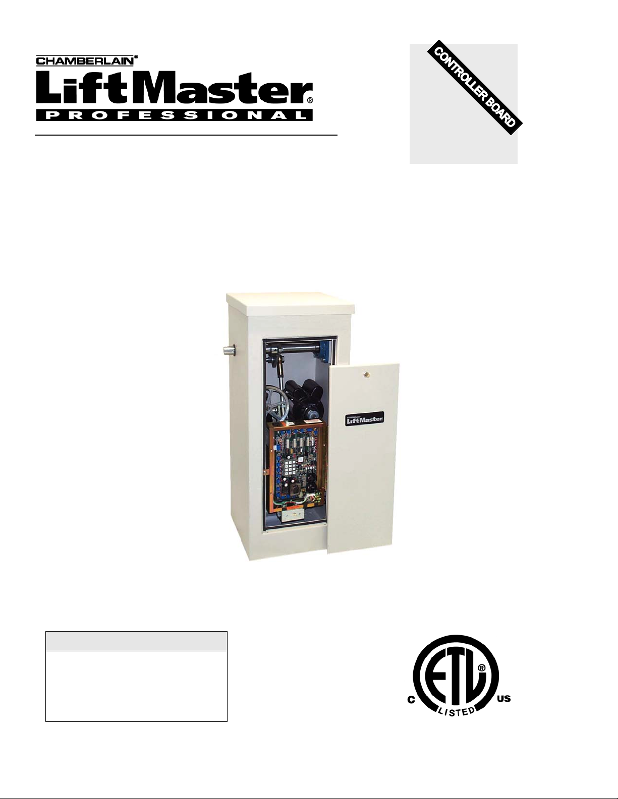
The LiftMaster Model BG 3000-B3
The LiftMaster Systems model BG 3000-B3 Barrier Gate Operator is a full featured commercial gate operator
with master/slave wiring capability. The BG 3000-B3 contains the following standard features:
• Dynamic motor braking limits gate overtravel.
• Alternate action OPEN/CLOSE inputs.
• Manual switch inputs override other commands.
• Adjustable reclose timer.
• Gate lock relay can be used for electromagnetic locks and CCTV cameras or
lights.
• Master-slave operation for two operators on bi-part gates and vehicle trap
gates.
• Selectable anti-tailgate function prevents two cars from entering on one open
command.
• Open Motor detection indicates when the motor is not drawing any current.
• Maximum run time feature stops a run-away motor.
• Motor Overload sensing protects the gate operator from excessive motor
current.
• Senses obstructions through adjustable Peak and fixed average motor current
senses.
• Two separate peak motor current sense adjustments; one for upward motion
and the other for downward motion of the arm.
• Start-up current sense adjustment offsets initial inrush current to the motor.
• Selectable Automatic Gate Closure feature closes the gate when power is
restored after an outage if gate is at open limit.
• Two 115 VAC accessory plugs provided.
• 24 VAC accessory power provided.
• 60:1 worm gear reducer provides quiet operation.
• 90 degree arm rotation in less than 4.3 seconds.
• Handles any gate weight up to 10 pounds and length up to 12 feet.
• Diagnostic LEDs on controller board indicate gate operator actions and assist in
troubleshooting.
• Optional loop detector add-on boards plug into the controller board for
Interrupts, shadow and exit loops.
• Interrupt Bar input is included for use with edge sensors.
Inside and outside Interrupt Loops and Photo-Sensor Inputs enhance gate
•
control and distinguish between entering and exiting traffic.
• Optional arm for safe and long service life.
DIMENSIONS WEIGHT ELECTRICAL
Height 44” 242 Lbs. 115 VAC, Single Phase, 60 Hz., 15 amp
Width 17” (A separate 20 AMP circuit is
Depth 17” required by most codes.)
Rev E Doc 01-20206 (6001521)
Page 5

SAFETY SUMMARY
It is important for everyone involved in the installation and operation of the LiftMaster model BG
3000-B3 Barrier Gate Operator reads the following warnings.
WARNING!
• A vehicle gate is a large, heavy object that is moved by an electric motor. A moving
gate can cause serious injury or death! The safety and well-being of others depends
on the installation of a safe system.
• Improper installation of a gate operator can result in a dangerous system.
• Gate operators can present serious hazards to persons in the immediate area when
not controlled in a safe manner. Choose one or more controls which together will
allow complete control of the gate. Most importantly, the gate must be able to be
stopped at all times in case of emergency, and the emergency control should be
conveniently located, clearly marked and visible.
• All controls must be kept out of the reach of small children. Serious injury or death
can result from children playing with the controls.
• All controls should be located so the person operating them can see the full area of
gate movement.
• Gate operators and associated control equipment should be installed by qualified
professional installers who should observe the following safe installation procedures:
1. Power should always be disconnected whenever installing, wiring or servicing a
gate operator. Moving chains and belts in gate operators can catch clothing or
fingers and cause severe injury.
2. Installation of wiring should comply with all local building and electrical codes.
3. All manual gate locks should be disabled to avoid damage to the gate or gate
operator should the lock become engaged after the operator is installed.
4. All operator controls and safety equipment should be tested at the conclusion of
installation to be sure they are functioning properly.
5. The operation of the gate controls and safety equipment should be reviewed with
the owner and/or end user of the automated gate system. They should also be
informed of the need to maintain control and safety equipment on a regular basis.
Safety equipment should be checked monthly to ensure it is working properly. All
installation manuals and safety information should be left with the owner.
6. Moving gates have pinch points and entrapment zones which can be extremely
dangerous to pedestrians, especially small children.
Rev E Doc 01-20206 (6001521) 1 of 36
Page 6

BASIC INSTALLATION HINTS AND RULES
PLEASE READ THIS SECTION CAREFULLY BEFORE BEGINNING YOUR INSTALLATION.
The sections that follow contain detailed procedures for installation of a model BG 3000-B3 system. In
addition to these specific procedures, there are a number of general hints and rules which will help
ensure that your installation will be done correctly and efficiently. These are discussed below.
1. UNDERSTAND THE SYSTEM AND INSTALLATION SITE THOROUGHLY. The BG 3000-B3 is a
flexible and reliable gate operator system, but the quality of service depends directly on the quality of
installation. Please read these instructions carefully and study the applicable diagrams before planning
your installation. In particular, understand any site characteristics that may affect the system
installation.
WARNING
2. INSTALL PERMANENT WIRING. U.L. specifications require the BG 3000-B3 system to be
permanently wired. Refer to your local wiring code for specific information.
WARNING: Damage caused by faulty wiring is not covered by warranty.
3. GROUND THE SYSTEM. The system contains parts which may be damaged by static discharge. A
proper earth ground connected to the gate operator housing (see Figure 3) will significantly reduce the
chances of damage or improper operation. The shielding in the cables specified for all remote sensors
and controls should also be connected to earth ground at the controller end of the cable only.
To be effective, the ground connection must be made by running 12 awg copper wire to a good ground
point (e.g., an electrical panel, a metallic cold water pipe that runs into the earth, or a grounding rod at
least 10 feet in length that is driven into the earth) within 12 feet of the system. Even if you have a
good earth ground, you should try to discharge any static before handling the circuit boards.
WARNING: Damage caused by static discharge and lightning is not covered by warranty.
4. PROVIDE POWER FROM A DEDICATED SOURCE. The outlet into which you connect the Gate
Operator should be wired to its own circuit breaker. This will reduce the line noise introduced into
system power and minimize the risk of having other equipment interrupt system operation. In a
Master/Slave system, Master and Slave must each have separate circuits (see the manual,
Installation and Operation, Master/Slave Systems for Series B3 Gate Operators).
5. DO NOT OVERLOAD THE TERMINAL BLOCKS. The terminal blocks used in the gate operator are
removable and the pins are soldered into the boards. To connect your wires, remove the "head" from
the correct terminals and open the screws. Insert the wire into the correct opening on the front and
tighten the screw until the wire is held firmly. When you have made all connections for a given "head",
plug it back onto the pins designated for that terminal block.
Stranded wire must be between 16 and 24 awg. Solid wire must be between 18 and 24 awg. This is
the total thickness measurement so, if you are putting two wires in, the combined thickness must fall
within this range. NEVER try to insert more than two wires per terminal.
6. ENSURE GOOD CONNECTIONS. A light tug on the wire will tell you if the connection is secure.
When reconnecting system components, make sure all pins are straight on chips, connectors, and
terminal block heads.
7. READ THE MARKINGS CAREFULLY. The connection points are marked on the boards clearly.
Before making any connection, be sure to read the marking and check it against the corresponding
figure in these instructions so that you understand the connection you are making.
8. TRAIN YOUR CUSTOMERS THOROUGHLY. Although customer responsibility is limited to proper
installation, the quality of service is determined by the care of system setup. Ensure that the customer
has a copy of this manual to guide them. It will save you and them lots of inconvenience and
aggravation later.
Rev E Doc 01-20206 (6001521) 2 of 36
Page 7
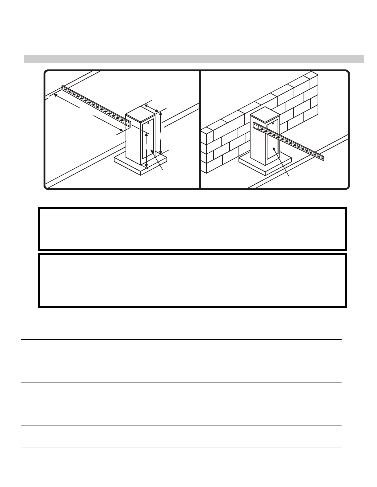
A. LOCATION AND LAYOUT
TYPICAL INSTALLATION RESTRICTED INSTALLATION
12' Max.
PART 1
SITE PREPARATION
17"
44"
35"
Access Door
Access Door
01-20206F1
Figure 1. Barrier Gate Operator Layout.
NOTE
Figure 1 shows two different single gate installations. For location and layout details of Bi-Parting,
Bi-Parting Latch, Trap and Tandem gates, see Installation and Operation of Master/Slave Systems
for Series B3 Gate Operators.
1. Always install the gate operator on the inside of the gate perimeter. NEVER install on the
public side of the perimeter.
2. All manual controls and activating devices should be mounted at least 6 ft. away from the gate
to provide safety.
3. Allow enough clearance around the gate and the gate operator for installation and service.
INSTALLATION NOTES
Rev E Doc 01-20206 (6001521) 3 of 36
Page 8
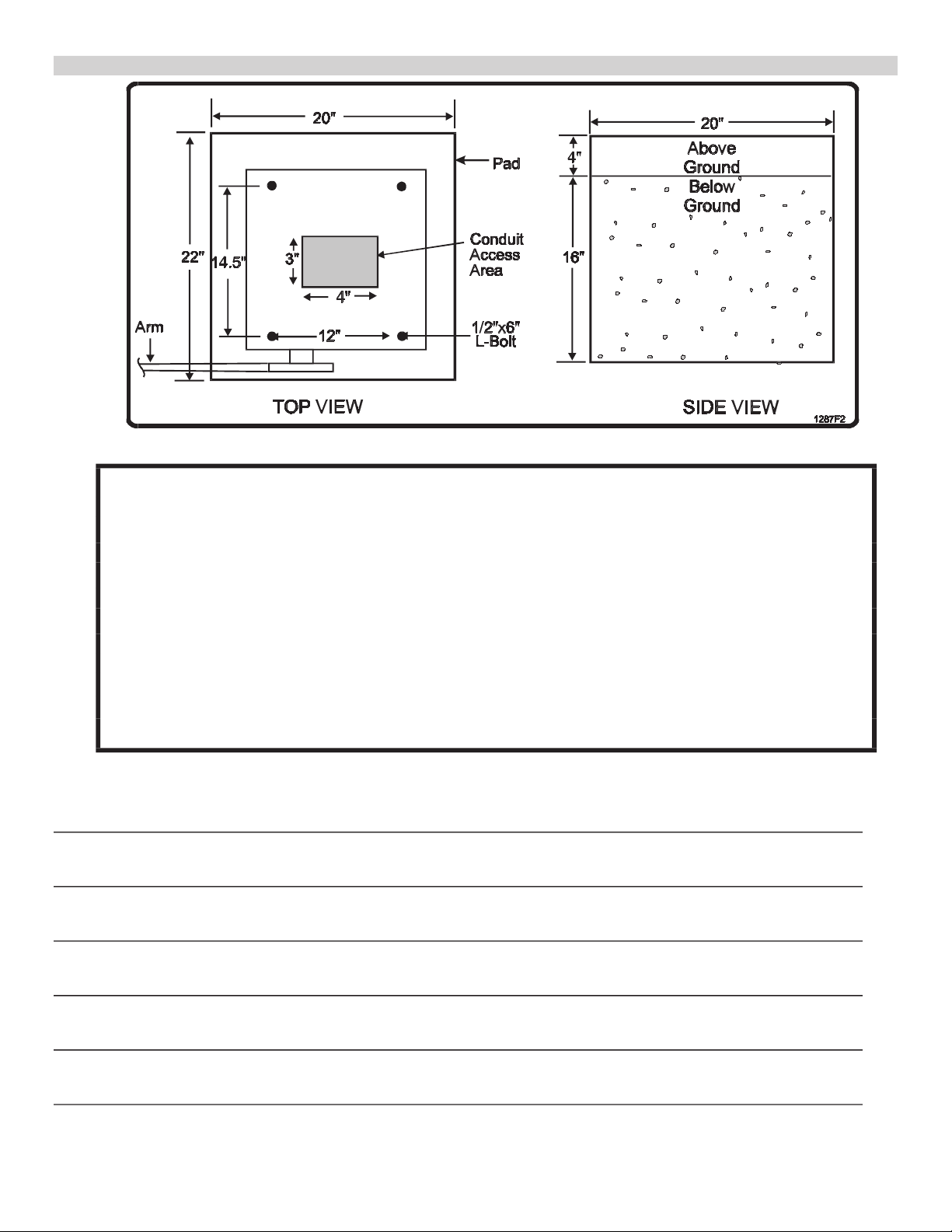
B. PAD AND MOUNT
The concrete pad must be sufficient to support the gate operator and the dynamic forces
1.
created by the moving gate. LiftMaster recommends a pad 20” wide by 22” long by 20” deep.
2. Four anchor bolts are required to secure the gate operator to the pad. The mounting holes in
the gate operator are 5/8” in diameter. L-bolts 1/2” x 6“ are recommended.
3. The pad should be level and about 4” above grade to prevent water entrance. Allow concrete
to set at least two days before installing gate.
4. Be sure to provide access for wiring conduits. In Master/Slave systems, remember to include
conduit stubs for separate inputs (if any) and for the Master/Slave connection cable between
gate operators. For more information, see Installation and Operation of Master/Slave Systems
for Series B3 Gate Operators.
NOTE: The only access area for the conduit stub is at the center of the pad, indicated as the
shaded area in Figure 2 Top View. Allow a minimum three-foot-long conduit stub.
Figure 2. Pad and Mount.
INSTALLATION NOTES
Rev E Doc 01-20206 (6001521) 4 of 36
Page 9

C. POWER WIRING
1.
Provide a separate conduit stub for the AC power.
2. Each gate operator requires a 115 VAC 20 AMP single phase circuit. NOTE: Master and
Slave units each require separate circuits to prevent false overcurrent faults.
3. Wire Size/Length Requirement: comply with the local Electrical Code for operating a 1/2 HP
motor (suggest 12 AWG/up to 300’ and 10 AWG/up to 500’).
4. Be sure to pull a ground wire in the conduit for the connection to the gate operator. Do not rely
on metallic conduit for earth ground.
D. LOOP DETECTORS
1.
The gate operator has a shelf that can support non-LiftMaster loop detector electronics. Power
for the loop detector can come from the auxiliary 115 VAC plugs in the gate operator or from
the 24 VAC provided by the gate operator control board.
NOTE: The auxiliary plugs have power regardless of the unit power switch setting.
2. Conduit provisions should be made for the “loop” wire entrance to the loop detector.
3. Available shelf space: 13" x 7".
4. Wire Size/Length Requirement: 16-24 AWG stranded or 18-24 AWG solid wire/up to 3000’.
NOTE: Optional LiftMaster-supplied loop detector add-on boards are available, both pre-installed
and for installation in the field. See Part 4, BG 3000-B3 Options.
E. MASTER/SLAVE INTERCONNECTION (MASTER/SLAVE SYSTEM ONLY)
A conduit between the Master and Slave units should be provided for the Master/Slave
1.
interconnection cable.
2. Wire Size/Length Requirement: Two shielded twisted pair wire 16 AWG to 24 AWG/up to 3000’
will be connected between the two units through the conduit at TB1 on the controller board.
NOTE: Do not run the Master/Slave cable and AC power wires in the same conduit.
F. OTHER CONNECTIONS
1.
Provisions should be made for conduit entrance into the gate operator for external
activating devices such as key switches, telephone entry systems, loops, etc.
2. Wire size/Length Requirement: 16-24AWG stranded or 18-24AWG solid wire/up to 3000’.
G. GROUNDING
1.
The system contains parts which may be damaged by static discharge. A proper earth
ground connected to the gate operator housing will significantly reduce the chances of
damage or improper operation. The shielding in the cables specified for all remote sensors
and controls should also be connected to earth ground at the controller end of the cable
only.
2. To be effective, the ground connection must be made by running 12 AWG copper wire to a
good ground point (e.g., an electrical panel, a metallic cold water pipe that runs into the
earth, or a grounding rod at least 10 feet in length that is driven into the earth) within 12 feet
of the system. Even if you have a good earth ground, you should try to discharge any static
before handling the boards.
Rev E Doc 01-20206 (6001521) 5 of 36
Page 10
SYSTEM INSTALLATION
A. MOUNTING GATE OPERATOR
To avoid injury, always turn off the unit power switch before working on gate.
1. Mount the cabinet on the cement pad using the previously installed anchors. Be sure the
operator mounting is level and square, and that the gate operator access door faces away
from the driveway (see Typical Installation, Figure 1).
2. Slightly loosen the mounting screws of the control box clear plastic cover. Slide the
cover out.
3. Swing the control box open fully to allow connection of the conduits. Run the conduits
through the bracket in the lower back of the control box.
4. Cut excess conduit and use 90 degree conduit fittings to attach conduits to the control box.
Note: the input power conduit need not go through the bracket and can be attached to the
control box directly.
After attaching the conduits to the control box, make sure that: a) the conduits fold to the right
during control box closure; and b) the control box swings freely open or closed.
PART 2
WARNING
IMPORTANT NOTE
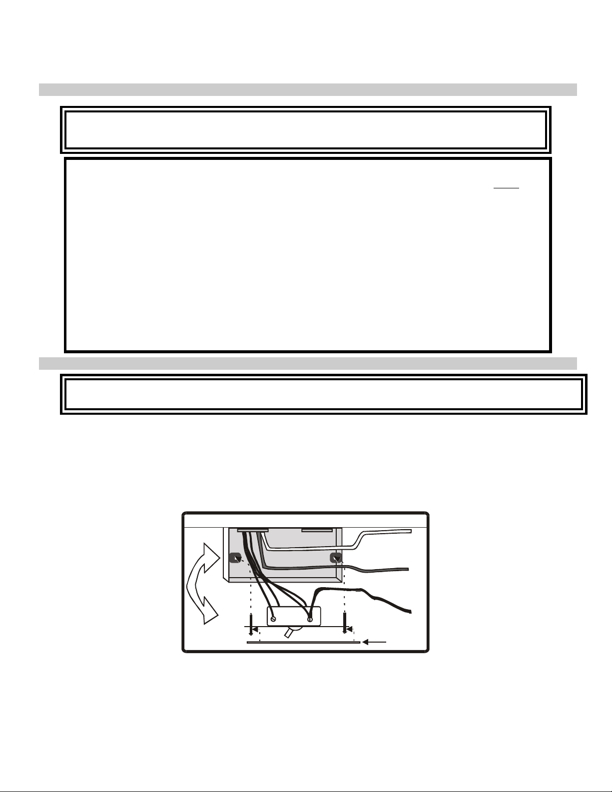
B. CONNECTING POWER
Ensure that the AC power circuit breaker is turned off before wiring power to the switchbox.
Run power cables through the conduit to Gate Operator, then connect wires to the switch box (see
Figure 3).
1. Wire nut the hot (black) wire to the black pig tail.
2. Wire nut the neutral (white) wire to the white pig tail.
3. Wire nut the ground (green) wire to the green pig tail.
4. Dress all wiring inside the switch box and install switch and face plate.
01-20206F2
CAUTION
CONTROL BOX
SWITCH
White Wire
Green Wire
Black Wire
Face Plate
Figure 3. AC Wiring.
Rev E Doc 01-20206 (6001521) 6 of 36
Page 11
C. RUNNING INPUT WIRING
1. Run wires from input components and Master/Slave conduits into control box.
2. For Master/Slave wiring, refer to Installation and Operation of Master/Slave Systems for
Series B3 Gate Operators.
WARNING
Route but do not connect input wires at this time. If inputs are connected now, the gate operator
may activate at random during installation, potentially injuring installation personnel.
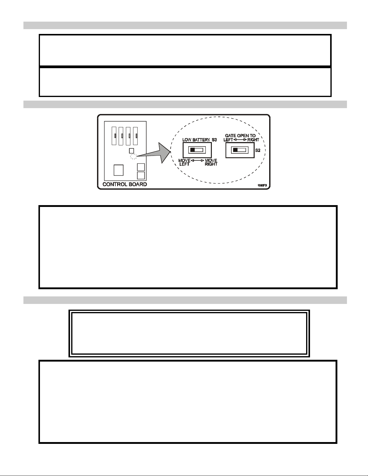
D. SETTING GATE OPEN DIRECTION SWITCHES S2 AND S3
Figure 4. Gate Direction & Option Switch Location.
1. Gate opening direction is set by switch S2, located on the control board. The switch is sensed
only on power up, so it should be set when the power is off.
2. Ensuring power is off, set switch S2 to the left if the cabinet access door faces away from the
driveway (typical installation), or to the right if the access door faces the driveway (restricted
installation).
3. Set S3 switch to the direction you wish the gate to move (open or closed) after a power outage
when LOW BATTERY input is activated by an Uninterruptable Power Supply (UPS). Switch
set to left: gate fully opens after power outage. Switch set to right: gate fully closes after
power outage.
E. POWER UP PROCEDURE
If gate is positioned at the 'open' limit, gate will automatically close if Reclose
Timer is enabled and power is switched on. Position gate either at the closed
limit or at no limit when preparing to switch power on. Always use extreme
caution and follow all warning in the Safety Summary.
1. Turn on circuit breaker that provides power to gate operator.
2. On Manual Input Terminal TB2, connect the STOP terminal to the COMMON terminal (see
Figure 5).
3. Turn on gate operator power switch and verify that the row of LEDs on the right side of the
controller board all turn on, then turn off sequentially, starting from the bottom. The only LEDs
that should remain on are Power ON, MAGLOCK, and CLOSE LIMIT or OPEN LIMIT, if one of
the limit switches are engaged.
NOTE: If the LEDs do not follow this pattern, the controller board may not be working
correctly. Stop installation and call LiftMaster Technical Support for assistance.
CAUTION
Rev E Doc 01-20206 (6001521) 7 of 36
Page 12
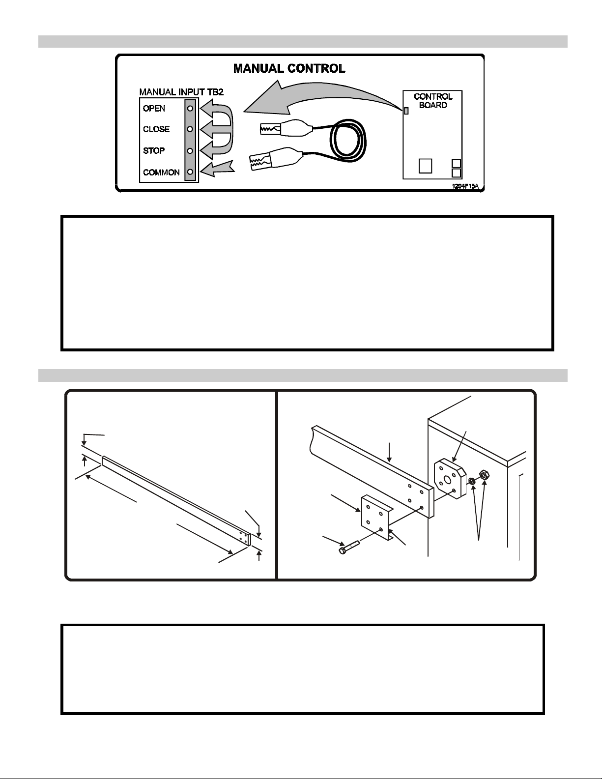
F. USING MANUAL CONTROLS
Figure 5. Manual Controls, Location and Use.
If necessary, use the manual controls on Manual Input Terminal TB2 (OPEN, CLOSE, and STOP,
as shown in Figure 5), to move the gate arm during system installation.
• To open the gate: connect the OPEN and STOP terminals to the COMMON terminal.
• To close the gate: connect the CLOSE and STOP terminals to the COMMON terminal.
• To stop the gate: disconnect the STOP terminal from the COMMON terminal.
If the STOP terminal is disconnected from the COMMON terminal, the gate is prevented
from moving and no command will affect the gate.
IMPORTANT NOTE
G. GATE ARM INSTALLATION
ARM FABRICATION
3"
12' Max.
NOTE: Use 1"X6" Pine or Redwood.
1. ARM FABRICATION
1. Use 1" x 6" clear pine or redwood (not supplied).
2. Cut arm to the desired length (up to 12 feet), then taper to dimensions shown in Figure 6.
Tapering the arm reduces weight and reduces warping.
3. Using the arm clamp as a template, drill four 1/2" diameter holes in the wide end of the arm.
4. Finish the arm using an exterior grade paint. Add striping with paint or tape.
ARM ATTACHMENT
Arm
Clamp
5 1/2"
Hex Bolt
1/2-13 X 2 1/4
(4 places)
Figure 6. Gate Arm Installation.
Gate
Arm
Unfolded
Edge
Hub
Flange
Lockwasher,
1/2" Hex Nut
(4 places)
01-20206F3
Rev E Doc 01-20206 (6001521) 8 of 36
Page 13

CAUTION
The total weight of the gate arm must not exceed ten (10) pounds. The lighter and/or shorter the
gate arm, the longer the life of the gear reducer and motor.
1. ARM ATTACHMENT
1. Secure the hub flange to the output shaft using the two set screws and the key from the
accessory kit.
2. Align the holes in the gate arm with the attachment holes on the hub flange and arm clamp.
3. Install and tighten the four supplied hex bolts, lock washers and hex nuts (see Figure 6).
NOTE: Make sure the arm clamp is oriented as shown in the figure.
H. GATE ARM ADJUSTMENT FOR TYPICAL INSTALLATION
Although preset at the factory, the turnbuckle may have to be adjusted to ensure the gate arm is
level. If required, adjust the turnbuckle as follows:
1. Make sure the unit power switch is off.
2. Rotate the gearbox pulley by hand until the crank arm is in parallel with the turnbuckle shaft
at its lowest point of travel (see Figure 7).
3. If the gate arm is not level, loosen both turnbuckle jam nuts and rotate the shaft until the gate
arm is parallel with the ground, then retighten the two jam nuts.
Figure 7. Gate Arm Adjustment.
I. LIMIT CAMS
0
Gate operator limit cams are factory adjusted for 90
arm swing and are not to be adjusted in the
field except during limit cam or limit switch bracket replacement.
Rev E Doc 01-20206 (6001521) 9 of 36
Page 14

J. GATE SENSITIVITY ADJUSTMENTS
The gate operator monitors both average and peak motor current. When the gate encounters an
obstruction, the gate operator senses the change in motor current and stops or reverses the gate.
Three sensitivity adjustments are factory-set for most installations:
• Right gate motion (R78) @ 11:00 o'clock
• Left gate motion (R81) @ 11:00 o'clock
• Inrush current (R119) @ 9:00 o'clock
If your installation requires different sensitivity adjustments, use the following procedures:
♦ For Typical Installation, set switch S2 to “Open to Left” position and use the “Typical
Installation" adjustment procedures below. For Restricted Installation, set S2 to “Open to
Right” position and use the “Restricted Installation" adjustment procedures.
♦ The minimum sensitivity is full clockwise and maximum sensitivity is full counter clockwise.
These adjustments must be made while the gate is in motion.
♦ Before starting the adjustments, verify that the Left and Right obstruction pots are set fully
clockwise, and the Inrush pot is set to the 9 o’clock position (see Figure 10).
IMPORTANT: Current flow varies with temperature. Do not tune the sensitivity measurements too
finely, or they may cause false overcurrent fault to occur during cold weather.
♦ Make all adjustments in the order listed.
Figure 8. Gate Sensitivity Adjustments Location.
1. TYPICAL INSTALLATION ADJUSTMENTS
"Left Obstruction" Adjustment (R81)
1. Initiate opening the gate.
2. Wait 1 to 2 seconds, then lightly "tug” against the edge of the gate to simulate an obstacle.
3. If the gate does not stop, reclose the gate and adjust the pot slightly counterclockwise.
4. Repeat steps 1-3 until the gate stops when tugged and has the desired sensitivity.
"Right Obstruction" Adjustment (R78)
1. Open the gate fully, then initiate closing the gate.
2. Wait 1 to 2 seconds, then lightly "bump" the leading edge of the gate to simulate an obstacle.
3. If gate does not stop or back up, reopen the gate and adjust the pot slightly counterclockwise.
4. Repeat steps 1-3 until gate stops or backs up when bumped and has the desired sensitivity.
Rev E Doc 01-20206 (6001521) 10 of 36
Page 15

2. RESTRICTED INSTALLATION ADJUSTMENTS
"Right Obstruction" Adjustment (R78)
1. Initiate opening the gate.
2. Wait 1 to 2 seconds, then lightly "tug” against the edge of the gate to simulate an obstacle.
3. If the gate does not stop, reclose the gate and adjust the pot slightly counterclockwise.
4. Repeat steps 1-3 until the gate stops when tugged and has the desired sensitivity.
"Left Obstruction" Adjustment (R81)
1. Open the gate fully, then initiate closing the gate.
2. Wait 1 to 2 seconds, then lightly "bump" the leading edge of the gate to simulate an obstacle.
3. If the gate does not stop or back up, reopen the gate and adjust the pot slightly
counterclockwise.
4. Repeat steps 1-3 until the gate stops or backs up when bumped and has the desired
sensitivity.
3. START-UP CURRENT ADJUSTMENT (R119)
1. Turn the pot fully counterclockwise.
2. Initiate opening the gate.
3. If the gate stops due to a fault condition, slightly adjust the pot clockwise.
4. Repeat steps 2 and 3 until the gate cycles without a fault.
5. Open the gate fully, then initiate closing gate.
6. If the gate stops or backs up due to a fault condition, slightly adjust the pot clockwise.
7. Repeat steps 6 and 7 until the gate cycles without a fault and has the desired sensitivity.
Rev E Doc 01-20206 (6001521) 11 of 36
Page 16

K. CONNECTING INPUT WIRING
GROUND LUG
EXTERNAL GROUND
(SEE PAGE 5)
Figure 9. Control Board Wiring.
IMPORTANT: Before proceeding, see NOTES below.
1. Wire all external control devices to their connections on the control board as shown. See
Appendix A for details on how each control input affects the gate operator.
2. Connect the Master/Slave interconnect cable (see Master/Slave Systems for B3 Series
Gate Operators, Part 1).
Rev E Doc 01-20206 (6001521) 12 of 36
Page 17

NOTES
1. Disconnecting the STOP terminal from the COMMON terminal stops the gate and prevents all
commands from having any effect. Manual Open does not activate the Reclose Timer.
IMPORTANT: As per UL325 standards, install Manual Input and Fire switches in the line of
sight with the gate.
2. If gate(s) are used for bi-directional traffic, the Exit Loop should be a directional loop detector.
3. Inside and Outside Interrupt Loops:
♦ For maximum safety, Inside and Outside Interrupt loops require separate loop detectors.
♦ Bipart or Bipart Latch: If only one loop detector is used, the Outside loop must also be
connected to the Inside loop detector.
L. SETTING GATE CONTROL SWITCH S1 AND RECLOSE TIMER POT R94
NOTE: For complete details on controls, indicators, adjustments and inputs, see Appendix A.
GATE CONTROL SWITCH (S1) OVERVIEW
Figure 10. Gate Control Switch S1 Location And Details.
TIMER Sets the Reclose Timer to OFF (left) or ON (right). When enabled, the
(S1-1) timer controls how long the gate waits at the open limit before closing.
The Reclose Timer can be set from 0-250 seconds by adjusting the
Reclose Timer pot (R94). During a power outage, if the gate is fully
open and TIMER is ON, the Reclose Timer starts after the restoration of power,
causing the fully open gate to close automatically.
ATG Sets Anti-Tailgate function to OFF (left) or ON (right). The Anti-Tailgate
(S1-2) feature helps prevent two cars from entering on one OPEN command.
See Paragraph 2 below for setting instructions. ATG is not functional
with swing gates.
SLIDE Use this switch with S1-4 to configure the gate type. To set the gate to
(S1-3) SWING, set switch to OFF (left).
SWING Use this switch with S1-3 to configure the gate type. To set the gate to
(S1-4) SWING, set switch to ON (right).
MASTER/ Set in conjunction with S1-6 and S1-7, configures the gate operator for
SINGLE master/slave operation. For settings, see B3 Series Master/Slave
(S1-5) Systems.
Rev E Doc 01-20206 (6001521) 13 of 36
Page 18

BIPART Set in conjuction with S1-5 and S1-7, configures the gate operator for
(S1-6) master/slave operation. For settings, see B3 Series Master/Slave
Systems.
LATCH/TRAP Set in conjunction with S1-5 and S1-6, configures the gate operator for
(S1-7) master/slave operation. For settings, see B3 Series Master/Slave
Systems.
(NOT USED) This switch is not used.
(S1-7)
1. SETTING RECLOSE TIMER SWITCH (S1-1) AND POT (R94)
Figure 11. Reclose Timer Enable and Adjustment Location.
The Reclose Timer pot (R94) is adjustable from 0 to 250 seconds. Turning the pot clockwise
increases the reclose time. NOTE: Pot in figure is set to 0 seconds.
1. To enable the Timer, set switch S1-1 (TIMER) to ON (right).
2. Turn the pot fully counterclockwise.
3. Open the gate. Gate should close almost immediately when it reaches the open limit.
4. Adjust the pot slightly clockwise.
5. Open the gate. Note delay between gate reaching it's open limit and starting to close.
6. Repeat steps 4 and 5 until the desired relcose time is set.
2. SETTING GATE TYPE TO SWING (Switches S1-3 and S1-4)
1. Set switch S1-3 (SLIDE) to OFF (left).
2. Set switch S1-4 (SWING) to ON (right).
3. SETTING MASTER/SINGLE GATE (Switch S1-5)
• For a single gate, set switch S1-5 (MASTER/SINGLE) to ON (right).
• For a master/slave gates:
1. Master: Set switch S1-5 (MASTER/SINGLE) to ON (right).
2. Slave: Set switch S1-5 (MASTER/SINGLE) to OFF (left)
3. See B3 Series Master/Slave Systems for further instructions.
Rev E Doc 01-20206 (6001521) 14 of 36
Page 19

M. POST INSTALLATION PROCEDURES
1. Setup
1. Turn on the main power at the gate operator's circuit breaker.
2. Verify that switch S2 (the Gate Open Direction switch) is set to the correct position.
3. Turn on the unit power switch.
2. Manual inputs
1. Verify that Manual Open fully opens the gate and that the open limit switch stops the gate.
2. Verify that Manual Close fully closes the gate and that the close limit switch stops the gate.
3. Verify that Manual Stop stops the gate.
Note: If the gate stops due to a Obstruction Fault, readjust the gate sensitivity pots.
3. Mechanical
Use the Manual Input commands to verify that:
1. The gate swings open and closed smoothly.
2. There is no squeak or vibration in the gate when it is moving .
3. There is no belt slippage when the gate moves or stops.
4. Both gates open and close at the same time (Bi-Parting gates only).
4. Gate sensitivity
1. Left/Right Obstruction sensitivity:
Apply a bump to the opening and closing gate and verify that the gate reverses.
2. Start-up (Gate response time) :
Apply a bump to the gate as it initiates opening and closing and verify that the gate
responds to the bump within a second.
5. Entry inputs
1. Activate the CYCLE input (entry system), RADIO input (radio transmitter), and EXIT Loop
input (driving over the exit loop) and verify that they fully open the gate. If Reclose Timer is
ON, it will close the gate.
2. Activate the FIRE input (fire department switch) and verify that the gate fully opens and then
closes immediately. If Reclose Timer is ON, it will close the gate.
6. Alternate Action
1. If you want the CYCLE input (Entry system) or RADIO input (Transmitter) to both open and
close the gate, on switch S1 set TIMER to OFF and ATG to OFF.
2. Activate the CYCLE command, wait until the gate is fully open, then activate the CYCLE
command again. The gate should close, verifying Alternate Action operation.
Note: If you select Alternate Action, you cannot use ATG = ON and TIMER = ON in
procedures 8 and 9 that follow.
Rev E Doc 01-20206 (6001521) 15 of 36
Page 20

7. Reclose Timer
1. If you want a fully open gate to automatically close after a period of time, on switch S1, set
TIMER to ON and adjust Reclose Timer pot R94 to set the time period.
2. If you don't want the gate to close automatically, on switch S1, set TIMER to OFF.
3. Activate any entry command (except Manual OPEN) to open the gate and verify the Reclose
Timer operation.
NOTE: Reclose Timer is not functional when the Manual Open command is used.
8. Inside Interrupt Loop and ATG (when exiting)
1. If you want a closing gate to open when a vehicle drives on the Interrupt Loop, on switch S1,
set Gate Type = Barrier and ATG to OFF.
2. If you want a closing gate to stop when a vehicle drives on the Interrupt Loop and an
opening or closing gate to close when the vehicle drives off the Interrupt Loop, on switch S1,
set Gate Type = Barrier and ATG to ON.
3. Activate the CYCLE command, drive over the Interrupt Loop, and verify its operation.
9. Interrupt Bar
While the gate is opening , push on the Interrupt Bar. The gate should reverse.
10. Automatic Gate Closure
1. To automatically close a fully open gate after power is restored, on switch S1, set TIMER to
ON.
2. Open the gate fully, then cycle the unit power switch to verify Automatic Gate Closure
operation.
N. FINAL ASSEMBLY OF GATE OPERATOR
Figure 12. Gate Operator Final Assembly.
1. Install gate operator top cover and secure with two wing nuts.
2. Swing hinged control box into cabinet and secure in place with hardware provided.
3. Install clear cover on control box and secure with the four screws provided.
4. Make sure that gate operator unit power switch is turned on.
5. Install gate operator cabinet access door and lock.
6. Cycle the gate to ensure it is operating properly.
Rev E Doc 01-20206 (6001521) 16 of 36
Page 21

PART 3
MODEL BG 3000-B3 OPTIONS
A. LIFTMASTER LOOP DETECTOR BOARDS
The model BG 3000-B3 has connectors for four LiftMaster-supplied loop detector add-on boards. These
boards interface with Interrupt and Exit loop sensors, which simply plug into the control board. The add-on
boards can be ordered pre-installed, or can be installed in existing model BG 3000-B3 units.
B. GATE OPERATOR ARM
• The standard arm is 12 feet long and weighs 10 pounds. It is tapered to reduce weight and to
prevent warping, and is painted white with black striping to enhance its visibility.
• An optional articulated arm is available for installations with limited overhead space.
Rev E Doc 01-20206 (6001521) 17 of 36
Page 22

PART 4
TROUBLESHOOTING AND MAINTENANCE
A. TROUBLESHOOTING
This section is designed to help you troubleshoot your unit(s) with a minimum of effort. Directly below are
some hints to help you test, then a list of problems in order of most severe to least. Next comes a quickreference list of faults and how to clear them, and then a list of faults and their causes.
Testing Control Board inputs: To test an input, connect the input terminal to the COMMON
terminal on the Control Board and verify that its LED turns on momentarily. Normally, the Close
limit switch and Maglock LED's are on if the gate is fully closed, and Open limit switch and
Reclose Timer LED's are on if the gate is fully open. The Power ON and Manual STOP LED's
are always on.
Low input AC voltage: The voltage across connector J1 pins 1 (red wire) and 3 (white wire)
on the Control Board must measure 100VAC to 130VAC.
CAUTION HIGH VOLTAGE. Measure with care.
Fault Causes: Refer to the end of trouble shooting section.
1. OPERATOR IS DEAD
When the unit power switch is cycled, no LED turns on.
1. The main circuit breaker is off.
2. The unit power switch is off.
3. The input power connector is not connected securely to the Control Board.
4. Low input AC voltage.
5. Bad Control Board.
2. OPERATOR DOES NOT RUN
When the unit power switch is cycled, LED's blink simultaneously or turn on randomly:
1. Low input AC voltage.
2. The processor was installed improperly into Control Board by the installer.
3. Bad Control Board.
When the unit power switch is cycled, all LED's turn on and off (except Power On) at the
same time:
1. On Manual Input Terminal TB2, the STOP terminal is disconnected from the COMMON
terminal.
2. An input is continuously activated (Stuck).
3. Low input AC voltage.
4. Bad Control Board.
When the unit power switch is cycled, all LED's (except Power On) turn on at the same
time and off one after another with the bottom LED turning off first (normal power up).
1. An input is continuously activated (stuck).
2. Both limit switches are stuck closed.
3. Stalled motor.
Rev E Doc 01-20206 (6001521) 18 of 36
Page 23

3. MOTOR DOES NOT RUN
Motor is dead:
1. The resettable motor thermal overload switch has popped.
2. The interconnecting cable between the motor and the control board is disconnected.
3. Bad control board.
4. Bad motor.
Motor is stalled:
1. Frozen motor or gearbox.
2. V-belt is too tight.
3. Gate is too heavy.
4. THE CONTROL BOARD RESETS RIGHT AFTER GATE STARTS MOVING
1. Low AC voltage.
2. Inadequate and undersized power wiring between the main circuit breaker and the gate
operator.
5. GATE STOPS IMMEDIATELY AFTER IT STARTS
1. A Fault has occurred.
Mostly in cold weather or mornings:
2. Motor Overcurrent Fault has occurred; Start-up pot adjustment is set too low.
6. GATE STOPS A FEW SECONDS AFTER IT STARTS
1. Stuck limit switch.
2. Motor Overcurrent Fault.
7. GATE STOPS WHILE OPENING OR REVERSES WHILE CLOSING
Motor Overcurrent Fault.
8. OPENING GATE STOPS WHEN A VEHICLE APPROACHES THE GATE
Gate Type on switch S1 is set improperly, causing the Interrupt loop to stop the gate.
9. GATE OPENS BUT DOES NOT CLOSE
1. Reclose Timer is OFF.
2. One of the inputs is continuously activated (a stuck input).
3. Entry system is connected to the Manual Input.
Rev E Doc 01-20206 (6001521) 19 of 36
Page 24

10. GATE DOESN'T STOP AT THE LIMIT
1. Limit cams are out off adjustments.
2. Limit switch cable is disconnected either from the control board or the limit switches.
3. Bad or miswired limit switch.
11. GATE IS TOO SLOW
1. Low input AC voltage
2. Slipping belt.
12. GATE DOESN'T STAY OPEN/CLOSED WITH MANUAL/FIRE INPUTS
1. Manual inputs or Fire were only activated momentarily not continuously.
13. GATE DOES NOT CLOSE AUTOMATICALLY
1. Reclose timer setting is OFF.
2. The entry system is connected to Manual open by mistake.
3. An input is continuously activated (stuck ).
14. ALTERNATE ACTION DOES NOT WORK
1. ATG or Reclose Timer is ON.
2. Entry system is connected to the Manual Input.
15. GATE DOES NOT OPEN TO THE CORRECT DIRECTION
1. Improper setting on switch S2
2. The power was not cycles after changing the setting of switch S2.
16. AN OPEN GATE DOES NOT CLOSE AT POWER UP
1. An input is continuously activated (Stuck).
2. The gate was not on the open limit switch when the power went out.
3. TIMER on switch S1 is set to OFF.
17. ATG (ANTI-TAILGATE) DOES NOT WORK
1. The ATG setting on switch S1 is OFF.
2. Entry system is connected to Manual Open.
3. Interrupt loop or loop detector is not working properly.
18. INTERRUPT LOOP DOES NOT ACT PROPERLY
1. Improper Gate Type and ATG settings on switch S1.
2. Bad loop sensor or loop detector.
3. Bad connection between the loop sensor, loop detector and the Control Board.
Rev E Doc 01-20206 (6001521) 20 of 36
Page 25

19. MASTER/SLAVE SYSTEM
Units are not synchronized:
Improper switch S1 Master/Slave settings.
Dynamic braking in one gate causes an obstruction fault in the other (moving) gate:
1. Both units are wired to the same circuit breaker.
2. Undersized power wires.
B. FAULT LIST
The following conditions can cause a fault:
1. Instantaneous motor overcurrent (left/right obstruction sense) due to an object
physically obstructing the gate or gate track (UL 325 requirement).
2. Average motor overcurrent (overload) caused by excessive motor current (UL 325
requirement.
3. Interrupt Bar activation (edge sensor) due to physical contact with the edge sensor.
4. Inoperative motor caused by an open motor winding, broken or unconnnected input
motor wires, thermal overload, or unsupervised motor (UL 325 requirement).
5. Limit switch staying closed when gate is supposed to move, caused by a broken
V-belt, defective limit switch, or defective limit cams.
6. Maximum motor run time exceeding 75 seconds.
A. If faults 1 through 3 occur only once during opening or closing, the gate reverses a few
inches and stops. Fault may be cleared by removing the obstruction and cycling any
command (Manual Inputs, FIRE, Cycle, Radio, EXIT).
B. If two sequential faults (a combination of faults 1 through 3 and Photo-Sensor
activation) occur during opening or closing, gate stops and Obstruction Alarm sounds
off for 5 minutes. Fault may be cleared by removing the obstruction and cycling Manual
Inputs or FIRE.
C. If fault 4 occurs, gate stops and Obstruction Alarm sounds off for 5 minutes. Fault may
be cleared by cycling Manual Inputs or FIRE.
D. If faults 5 through 6 occur, gate stops. Fault may be cleared by cycling any command.
C. FAULTS AND THEIR CAUSES
1. IF OBSTRUCTION LED IS ON
1. The gate is blocked by an object.
2. OBSTRUCTION or STARTUP adjustment is set too low.
3. Cold weather: frozen motor or frozen gate wheels.
4. The Maglock does not disengage from the gate at the start of gate opening.
5. A sudden increase in input power.
6. Bad Control board.
7. Belt is too tight.
2. IF INTERRUPT BAR LED IS TURNED ON
Edge Sensor is activated. Clear obstruction and cycle the gate.
Rev E Doc 01-20206 (6001521) 21 of 36
Page 26

3. IF OPEN MTR LED IS TURNED ON
1. The motor thermal overload switch is popped.
2. The wires connecting the motor to the Control Board are disconnected
3. Bad motor.
4. Bad Control Board.
4. IF STUCK-LIMIT LED IS TURNED ON
1. A limit switch is stuck closed.
2. The belt was broken before the start of the gate movement.
3. Stalled motor at open or close limit.
4. Bad limit switch.
5. IF MAX RUN TIME LED IS TURNED ON
1. Limit cams do not engage the limit switches.
2. The belt or chain has been broken.
3. The belt slips during gate movement.
4. Limit switch cable is disconnected.
5. Bad limit switch.
6. Stalled motor.
Rev E Doc 01-20206 (6001521) 22 of 36
Page 27

D. MAINTENANCE
WARNING
To avoid injury, always turn off the unit power switch before working on gate.
Regularly performance of preventive maintenance is essential for reliable system operation because it
corrects small problems before they turn into emergencies. LiftMaster recommends performing
preventive maintenance every 6 to 12 months, depending upon gate usage.
• If the gate is installed in a private residence or small apartment house where usage is not
severe, yearly preventive maintenance is acceptable
• If the gate is installed in a high-traffic application, semi-annual preventive maintenance is
essential.
PREVENTIVE MAINTENANCE TASKS
1. Gate: must swing freely without any impediment. Tighten set screws if loose !. Check hub,
grease if necessary.
2. Limit switches: contacts must bounce back rapidly when they are pressed and released.
3. Belt: Check for wear and tension (20 to 25 lbs.). Adjust the AC motor up or down to set proper
tension.
4. Pulleys: must all line up and be firmly secured to their shafts. Tighten set screws if loose !.
5. Gear Box: Check for no oil leakage around the bushings. Do not oil gearbox.
6. Control board: Check for water damage or burned spots. All connectors secured to the board.
7. Wiring: Check all wirings for any insulation damage. Check for loose wire connections.
8. No Rust: Check for rust throughout the unit. Check corners for water entrapment.
9. Fire Open: Activate Fire department switch to verify emergency gate opening.
10. Gate Sense: Check for the gate sensitivity (refer to Part 2, System Installation, paragraph J,
Gate Sensitivity Adjustments).
11. External Sensors (loop, edge, photo): Check for proper operation.
NOTES: !: To prevent loosening, LOCTITE threadlocker 242 is applied.
Rev E Doc 01-20206 (6001521) 23 of 36
Page 28

The following table was provided to help you keep a record of the maintenance schedule. Write the inspection
date in the left-hand box and check (!) the boxes across as you perform your maintenance procedures.
MAINTENANCE SCHEDULE TABLE
Date Gate Arm
Limit
Switches
Belt Pulleys Gear Box
Control
Board
Date Wiring No Rust Fire Open Gate Sense Sensors
Rev E Doc 01-20206 (6001521) 24 of 36
Page 29

APPENDIX A
SYSTEM OPERATION REFERENCE
CONTROLS, INDICATORS, INPUTS AND ADJUSTMENTS
For detailed explanations of the Gate Operator's various, controls, indicators, inputs and adjustments,
refer to the following pages.
CONTROLS
SWITCH S1 (OFF/ON DIP switch with functions listed on right side of switch.)
TIMER Sets the Reclose Timer to OFF (left) or ON (right). When enabled, the
(S1-1) timer controls how long the gate waits at the open limit before closing.
The Timer can be set from 0-250 seconds by adjusting the Reclose
Timer pot (R94). During a power outage, if the gate is fully open and
TIMER is ON, the Reclose Timer starts after the restoration of
power, causing a fully open gate to close automatically.
ATG The ATG feature helps prevent two cars from entering on one OPEN
(S1-2) command.
ATG ON: Inside or Outside Interrupt Loop activation does not affect an
opening gate, and Inside Interrupt Loop deactivation closes an opening
gate. Inside or Outside Interrupt Loop activation stops a closing gate,
and when the loop deactivates the gate closes.
ATG OFF: Loops have no effect on an opening gate. Inside or Outside Interrupt
Loop activation opens a closing gate.
SLIDE Set in conjunction with switch S1-4; these switches select one of four
(S1-3) GATE TYPES (Slide, Swing, Barrier, or Linear).
SWING Set in conjunction with switch S1-3; these switches select one of four
(S1-4) GATE TYPES (Slide, Swing, Barrier, or Linear).
MASTER/ Sets the unit to MASTER or SLAVE for two-gate (one master and one
SINGLE slave) operation.
(S1-5)
BIPART When set in conjuction with switch S1-7, these switches select one of
(S1-6) four Master/Slave configurations (Bipart, Bipart-Latch, Trap, Tandem).
LATCH/TRAP When set in conjunction with switches S1-6, these switches select one
(S1-7) of four Master/Slave configurations (Bipart, Bipart-Latch, Trap, Tandem)
(NOT USED) This switch is not used.
(S1-8)
SETTING THE GATE TYPE
SLIDE Set switch S1-3 ON (right) and S1-4 OFF (left).
SWING Set switch S1-3 OFF (left) and S1-4 ON (right).
BARRIER Set switch S1-3 OFF (left) and S1-4 OFF (left).
LINEAR Set switch S1-3 ON (right) and S1-4 ON (right).
NOTES:
1. If Gate Type is set to SLIDE, gate brakes whenever it stops.
2. If Gate Type is set to SWING, gate brakes only when it reaches the open or close limit.
3. If Gate Type is set to BARRIER or LINEAR, the gate never brakes.
Rev E Doc 01-20206 (6001521) 25 of 36
Page 30

SETTING SWITCH S1 FOR MASTER/SLAVE OPERATION (DUAL-GATE SYSTEM)
MASTER/SINGLE On the master Gate Operator, set switch S1-5 ON (right). On the
(S1-5) slave gate operator, set switch S1-5 to OFF (left).
BIPART Set switch S1-6 ON (right) and switch S1-7 OFF (left).
BIPART-LATCH Set switch S1-6 ON (right) and switch S1-7 ON (right).
TRAP Set switch S1-6 OFF (left) and switch S1-7 ON (right).
TANDEM Set switch S1-6 OFF (left) and switch S1-7 OFF (left).
SWITCH S2
GATE OPEN TO Selects the direction the gate will open (left/right).
LEFT/RIGHT
SWITCH S3
LOW BATTERY Selects the direction the gate will move (left/right) and remain when
LEFT/RIGHT the Low Battery input is activated by an Uninterruptible Power Supply
(UPS).
INDICATORS
LED indicators light when controls and inputs are active. Additional indicators are as follows:
LEFT LIMIT Indicates that the LEFT limit switch is activated.
RIGHT LIMIT Indicates that the RIGHT limit switch is activated.
MTR LEFT Indicates that the gate is moving to the left.
MTR RIGHT Indicates that the gate is moving to the right.
XMIT Indicates data is being sent to the other unit in a Master/Slave system.
RECV Indicates data is being received from the other unit in a Master/ Slave
system.
TIMER ON Indicates the Reclose Timer is running. Timer is set at pot R94.
OBSTRUCTION Indicates the peak motor current threshold was reached. See Fault List in
Part 4, Troubleshooting and Maintenance.
INTERRUPT BAR Indicates Interrupt Bar (Edge Sensor) switch was activated
(EDGE SENSOR) and the motor was stopped.
OPEN MTR Indicates the motor is engaged, but is not drawing any current. The
thermal overload switch on the motor may need to be reset. See Fault
List in Part 4, Troubleshooting and Maintenance.
STUCK LIMIT Indicates that a limit switch is stuck closed.
MAX RUN TIME Indicates the motor ran for more than 75 seconds without reaching a limit
switch, and was stopped. Usually requires mechanical service. See
Fault List in Part 4, Troubleshooting and Maintenance.
MAGLOCK Indicates the Mag Lock is engaged.
OBSTRUCTION Indicates the Obstruction alarm has sounded after two
ALARM consecutive gate obstruction faults.
Rev E Doc 01-20206 (6001521) 26 of 36
Page 31

FUNCTIONAL INPUTS
NOTES: " The term "activation" means closing an input circuit (via a relay or switch), and may be
momentary or continuous. Momentary activations are superceded by any command.
Continuous activations are superceded only by an overriding command.
# Activating any command when gate is at the open limit stops the Reclose Timer. When
the command (except Manual CLOSE and STOP) is cleared, the Reclose Timer is reset.
MANUAL INPUTS: OPEN, CLOSE, AND STOP (TB2)
MAN OPEN Activation fully opens the gate. Continuous activation holds gate open.
MAN OPEN overrides Anti-Tail-gate (ATG), Reclose Timer, and all controls
but MAN STOP.
MAN CLOSE Activation fully closes the gate. Continuous activation holds gate closed.
MAN CLOSE overrides all controls but MAN STOP, MAN OPEN and FIRE.
MAN STOP De-activation stops opening and closing gates. MAN STOP overrides
Reclose Timer and all other controls, manual or automatic. If MAN STOP is
disconnected from its COMMON, no commands affect the gate.
ENTRY SYSTEM/FIRE SWITCH INPUTS (TB9)
CYCLE Reclose Timer OFF:
Activation opens the gate, which remains open until another command is
received. A CYCLE command when the gate is fully open closes the gate.
This Alternate action allows a single command to both open and close the
gate. CYCLE also opens a closing gate. If Anti-Tailgating (ATG) is ON,
Alternate Action is disabled. With ATG ON, the gate begins closing as soon
as the INTERRUPT LOOP clears.
Reclose Timer ON:
Activation opens the gate, then the Reclose Timer closes the gate. A
CYCLE command also opens a closing gate, but will not close a fully open
gate if the Reclose Timer is ON. If Anti-Tailgating (ATG) is ON, the gate
closes as soon as the INTERRUPT LOOP clears.
FIRE Activation opens the gate. Continuous activation holds the gate open. If
Reclose Timer is OFF, when FIRE is deactivated, gate closes immediately. If
Reclose Timer is ON, when FIRE is deacitvated, the Reclose Timer starts.
FIRE overrides all faults and commands but Manual STOP.
EXIT LOOP/SHADOW LOOP DETECTOR INPUTS (TB10)
EXIT LOOP Same as CYCLE, but does not close the gate when it is fully open.
SHADOW LOOP Activation prevents the gate from opening or closing so the gate won't hit a
vehicle. If the gate is already moving, or if the gate is not fully opened or
closed, this input has no effect (swing gates only).
INSIDE/OUTSIDE INTERRUPT LOOP DETECTOR (TB16)
IF GATE TYPE IS SWING OR LINEAR (ATG IS NOT FUNCTIONAL):
Inside Interrupt Loop:
Activation stops an opening or closing gate and deactivation opens the gate.
Outside Interrupt Loop:
Activation opens a closing gate.
IF GATE TYPE IS SLIDE OR BARRIER AND ATG IS OFF:
Inside Interrupt Loop:
Activation opens a closing gate.
Outside Interrupt Loop:
Activation opens a closing gate.
Rev E Doc 01-20206 (6001521) 27 of 36
Page 32

IF GATE TYPE IS SLIDE OR BARRIER AND ATG IS ON:
Inside Interrupt Loop:
Activation/deactivation closes an opening gate. Activation stops a closing gate
and deactivation closes the gate.
Outside Interrupt Loop:
Activation stops a closing gate and deactivation closes the gate.
INSIDE/OUTSIDE PHOTO-SENSOR (TB3)
IF GATE TYPE IS SWING OR LINEAR:
Inside Photo Sensor:
Activation stops a moving gate and deactivation restarts the gate.
Outside Photo Sensor:
Activation stops a closing gate and deactivation restarts the gate.
IF GATE TYPE IS SLIDE OR BARRIER:
Inside Photo Sensor:
Activation stops an opening gate and deactivation restarts the gate.
Outside Photo Sensor:
Activation stops a closing gate and deactivation restarts the gate.
INTERRUPT BAR INPUTS (TB11)
INTERRUPT BAR Activation causes gate to stop and reverse a few inches.
INS./OUTS. INT. SENSE / SHADOW SENSE / EXIT SENSE (TB12/TB13/TB14/TB15) INPUTS
INSIDE Input from an Inside Interrupt loop provides the signal for an
INTERRUPT optional LiftMaster loop detector add-on board. Operation is the
SENSE same as the Interrupt Loop input, above.
OUTSIDE Input from an Outside Interrupt loop provides the signal for an
INTERRUPT optional LiftMaster loop detector add-on board. Operation is the
SENSE same as the Interrupt Loop input, above.
SHADOW Input from shadow loop provides signal for optional LiftMaster loop
SENSE detector add-on board. Operation is the same as Shadow Loop
input, above.
EXIT Input from exit loop provides signal for optional LiftMaster loop
SENSE detector add-on board. Operation is the same as Exit Loop input, above.
RADIO INPUT (TB6)
RADIO RECV Convenience terminals provide power (24VAC, 200mA) and signal
connection for a radio receiver. Activation is the same as CYCLE.
MAG LOCK INPUT (TB4)
MAG LOCK NO and COM inputs can close a circuit (i.e., MagLock) when the Close Limit
switch is activated (the gate is fully closed).
NC and COM inputs close a circuit (security camera, camcorder, light, etc.)
when the Close Limit switch is deactivated (when gate is not fully closed).
MASTER/SLAVE I/O INPUT (TB1)
Input/output terminals are used to communicate with a second gate operator
in a Master/Slave system.
LOW BATTERY (TB18)
Activation fully opens or closes the gate, depending the setting of Switch S3.
Rev E Doc 01-20206 (6001521) 28 of 36
Page 33

OBSTRUCTION ALARM (TB17)
Relay contacts close to provide 24VDC alarm power if the gate has two
consecutive obstruction faults.
ADJUSTMENTS
OBSTRUCTION Adjustable pot controls gate sensitivity to blockages by the
RIGHT (R78) instantaneous rise in motor current. When the limit is exceeded,
gate stops and reverses a minimum of 2 inches.
OBSTRUCTION Adjustable pot controls gate sensitivity to blockages by the
LEFT (R81) instantaneous rise in motor current. When the limit is exceeded,
gate stops and reverses a minimum of 2 inches.
NOTE: LiftMaster gate operators have left and right obstruction sense adjustments
where other gate operators have only one. This allows greater flexibility of
installation. For instance, you can install a gate on an incline and not worry
about sacrificing downhill gate sensitivity.
START-UP Adjustable pot controls the delay in sensitivity to obstruction
(R119) sense inputs. This delay in sensitivity prevents the initial motor
start up current from causing a fault condition. The weight of the
gate determines this setting.
RECLOSE Adjustable pot controls the time delay between gate reaching full
TIMER (R94) open and starting to reclose. The Reclose Timer is adjustable
from 0-250 seconds.
CONNECTORS
PWR INPUT (J1) Connector for AC input power.
MOTOR POWER (J3) Connector for the motor cable.
LIMIT SWITCH (J4) Connector for the left/right limit switch cable.
LOOP DETECTOR Connector for optional LiftMaster Outside Interrupt Loop
(J15) detector add-on board.
LOOP DETECTOR Connector for optional LiftMaster Inside Interrupt Loop detector
(J12) add-on board.
LOOP DETECTOR Connector for optional LiftMaster Shadow Loop detector add-on
(J13) board.
LOOP DETECTOR Connector for optional LiftMaster Exit Loop detector add-on
(J14) board.
OBSTRUCTION Connector for factory installed Alarm.
ALARM
Rev E Doc 01-20206 (6001521) 29 of 36
Page 34

APPENDIX B
MODEL BG 3000-B3 PARTS LIST
14
8
16
13
10
9
15
12
11
19
20
18
27
7
6
5
4
3
2
1
17
21
22
24
23
01-20206F5
Rev E Doc 01-20206 (6001521) 30 of 36
25
26
Page 35

ITEM # PART # PART NAME ITEM # PART # PART NAME
1 10-18023 BG3000 Shelf 15 12-8032 Pillow Block
2 74-18028 Limit Switch Assy. 16 11-8031 Shaft
3 23-20087 Limit Switch 17 16-8001 4L340 V-Belt
4 10-18027
5 96-18016B Limit Switch Cable 19 10-18022 Top Cover
6 75-18015 Limit Cam Assy. 20 84-WN-3855 Wing Nut
7 13-8001 Rubber Grommet (Shaft) 21A 75-18024 BG3000 Motor Assy.
8A 75-18026 BG3000 Gear Box Assy. 21B 20-1050B-1R 1/2 HP AC Motor
8B 32-8001 60:1 Gear Reducer 22 17-2002 2" Pulley
9 17-2001 8" Pulley 23 96-18008B Motor Cable Assy.
10 07-8003 Lower Crank 24 74-18025 Control Box Assy.
11 12-8033 Lower Rod End 25 23-20088 DPST Switch
12 07-8005 Crank Link 26 10-8017 Door
13 12-8034 Upper Rod End 27 80-8001 Lock Assy.
14 07-8004 Upper Crank
Limit Switch Support
Bracket
18 13-8000
Door Gasket
Material
PARTS NOT SHOWN
PART NUMBER PART NAME
SN1110168 B3 Controller Board
44-18020 Control Box Cover
40-G0579 Service Disconnect Label
40-10231 115V 4A Label
77-18018 BG3000 Accessory Kit
07-8007 Arm Hub
10-8007M Arm Clamp
40-3505 DORCMA Warning Sign
01-20206 BG3000 -B3 Installation Manual
01-20201 B3 Master/Slave Manual
02-103 3-Button Control
Rev E Doc 01-20206 (6001521) 31 of 36
Page 36

APPENDIX C
LIMIT CAMS
Gate operator limit cams are factory adjusted for 900 arm swing, and never need to be adjusted in the
field. However, if long-term use requires replacing the limit cams, use the following procedure to install
and adjust the replacement limit cams.
• Remove old limit cams by loosening the locking screws and removing cams from the shaft.
• When installing replacement limit cams, ensure that the limit cams are centered over their
corresponding limit switches.
• Small adjustments are magnified by the length of the gate.
• To avoid damage to the gate and gate operator due to the gate overrunning its limits, perform
the following steps carefully:
1. REPLACING AND ADJUSTING LIMIT CAMS IN A TYPICAL INSTALLATION
Figure 13. Setting Limit Cams For A Typical Installation.
1. Make sure that switch S2 is set to the "Left" position.
2. Turn on gate operator power switch.
3. Using manual CLOSE and STOP, move the gate to its proper closed limit position.
4. If not already loose, loosen the locking screw on the left limit cam and turn the cam counterclockwise until it just barely closes the limit switch.
5. Tighten the left limit cam locking screw.
6. Using manual OPEN and STOP, move the gate to its proper opened limit position.
7. If not already loose, loosen the locking screw on the right limit cam and turn the cam clockwise
until it just barely closes the limit switch.
8. Tighten the right limit cam locking screw.
9. Open and close the gate to check the limit cam settings. If required, readjust the limit cams
until they are set properly.
Rev E Doc 01-20206 (6001521) 32 of 36
Page 37

2. REPLACING AND ADJUSTING LIMIT CAMS IN A RESTRICTED INSTALLATION
Figure 14. Setting Limit Cams For A Restricted Installation.
1. Make sure that switch S2 is set to the "Right" position.
2. Turn on gate operator power switch.
3. Using manual CLOSE and STOP, move the gate to its proper closed limit position.
4. If not already loose, loosen the locking screw on the right limit cam and turn the cam clockwise
until it just barely closes the limit switch.
5. Tighten the right limit cam locking screw.
6. Using manual OPEN and STOP, move the gate to its proper open limit position.
7. If not already loose, loosen the locking screw on the left limit cam and turn the cam counterclockwise until it just barely closes the limit switch.
8. Tighten the left limit cam locking screw.
9. Open and close the gate to check the limit cam settings. If required, readjust the limit cams
until they are set properly.
Rev E Doc 01-20206 (6001521) 33 of 36
Page 38

GLOSSARY
AC: Alternating Current. An electric current or voltage that reverses direction at regular intervals.
Alternate Action: Ability to open and close a fully open gate by using the same open command.
Arc: The area that is swept by a swing gate from fully closed to fully open position.
ATG: Anti-tailgating refers to a method of immediately closing an opening gate behind a vehicle so that
an unauthorized vehicle can not follow the authorized vehicle through the gate.
DC: Direct Current. An electric current of constant value flowing in one direction only.
Dynamic braking: Stopping the gate by activating the forward and reverse windings of the gate
operator motor in each half AC cycle.
Fault: An abnormal condition which causes the gate to stop to protect the gate and the user.
Gate sensitivity: The response of the gate operator to an exerting force against the gate.
Gear Box: A device that changes the speed and power of its driving force (motor).
Inrush current: Initial current drawn into an electrical device due to its capacitive or inductive nature.
Interrupt Bar or Edge: A switch which is installed at the edge of a gate to protect an object which is
situated between the gate and the gate frame.
LED: Light Emitting Diode. LEDs are indicators placed on the controller board which light up to
indicate an action in the system.
Limit switch: A switch which its closure indicates the gate has reached its open or close limit, causing
the gate to stop. There are two limit switches, open and close.
Limit cam: An object which its excursion corresponds to the gate traveling distance and closes the
limit switch at the open or close limit of the gate.
Loop sensor: A wire embedded in the ground for magnetically sensing large metallic objects (cars).
$ Exit or Open Loop: activation opens the gate.
$ Interrupt or Reverse or Reopen Loop: activation reverses or stops the gate.
$ Shadow Loop: activation prevents a fully open or closed gate from moving while a vehicle
is inside the arc of a swing gate.
Loop detector: An electronic device that is activated by a loop sensor sensing a metallic object.
Master/Slave: A synchronized system containing a pair of gate operators.
Maglock: An electric magnet which is used to secure the closed gate.
Pulley: A grooved wheel which transfers power via a belt.
Reclose Timer: An electronic timer which closes the fully open gate automatically.
RPM: Rotation Per Minute is a term to indicate the speed of an rotary object.
Sprocket: A toothed wheel which transfers power via a chain.
Thermal overload: A condition at which a heat producing device shuts off automatically when it
reaches a critical and damaging temperature level.
Torque: A force that causes rotation.
Rev E Doc 01-20206 (6001521) 34 of 36
Page 39

NOTICE TO CANADIAN USERS
NOTICE: The Industry Canada label identifies certified equipment. This certification means that the
equipment meets telecommunications network protective, operation and safety requirements as
prescribed in the appropriate Terminal Equipment Technical Requirements document(s). The
Department does not guarantee the equipment to the user’s satisfaction.
Before installing this equipment, users should ensure that it is permissible to be connected to the
facilities of the local telecommunications company. The equipment must also be installed using an
acceptable method of connection. The customer should be aware that compliance with the above
conditions may not prevent degradation of service in some situations.
Repairs to certified equipment should be coordinated by a representative designated by the supplier.
Any repairs or alterations made by the user to this equipment, or equipment malfunctions, may give the
telecommunications company cause to request the user to disconnect the equipment.
Users should ensure for their own protection that the electrical ground connections of the power utility,
telephone lines and internal metallic water pipe system, if present, are connected together. This
precaution may be particularly important in rural areas.
Caution: Users should not attempt to make such connections themselves, but should contact the
appropriate electric inspection authority, or an electrician, as appropriate.
Rev E Doc 01-20206 (6001521) 35 of 36
Page 40

COPYRIGHT© 2002
ALL RIGHTS RESERVED
This document is protected by copyright and may not be copied or adapted without the prior written
consent of LiftMaster. This documentation contains information proprietary to LiftMaster and such
information may not be distributed without the prior written consent of LiftMaster. The software and
firmware included in the LiftMaster product as they relate to this documentation are also protected by
copyright and contain information proprietary to LiftMaster.
FOR TECHNICAL SUPPORT OR TO ORDER REPLACEMENT PARTS, CALL OUR TOLL FREE NUMBER:
(800) 528-2806 Tucson, AZ Monday thru Friday 5 AM – 6 PM, Saturday, 7 AM – 3:30 PM (PST)
Visit us at www.liftmaster.com
 Loading...