

Page 1
AUTO RECONNECT TROLLEY
KIT (ARK)
Models MT and T
(1/3 & 1/2HP only)
PACKING LIST
1. Disconnect trolley straight arm from door curved arm.
2. Locate masterlinks at either end of trolley slider and disconnect
drive chain.
3. Remove front idler assembly at the head of the track. Remove
trolley slider.
PART # DESCRIPTION QTY
10-10203 Curved Arm 1
10-10204 Door Bracket 1
10-10205 Track Header Bracket 1
10-10371 Straight Arm 1
Trolley / Slide Caution Label 2
Door Opening Warning Sign 1
K75-10259 Track Spacer 2
K75-10387 Trolley Slider (Carriage) 1
K75-10388 Front Idler (Chain Tensioner) Assembly 1
K75-10406 Drive Link Assembly 1
Hardware Bag With (2) Two
#48 Master Links 1
Hex Head Bolt 3/8-16 X 3/4" 12
Hex Head Bolt 3/8-16 X 1-1/4" 3
Carriage Bolt 5/16-18 X 2" 2
Lock Nut, Serrated Flange 5/16-18 2
Lock Nut, Serrated Flange 3/8-16 14
Lock Nut, Nylon 3/8-16 1
1
Instructions to install Auto Reconnect Trolley Kit (ARK). Spring
loaded trolley features nylon inserts for quiet operation. Autoreconnect feature eliminates the need to manually re-attach the
door arm to the trolley after emergency disconnect.
BEFORE INSTALLATION
• Refer to disassembly instructions below for all existing
installations.
• Refer to owner's manual provided with operator for all
mounting and wiring instructions.
• Refer to backside for pre-assembly instructions of auto
reconnect trolley kit.
• Disconnect power to operator.
EXISTING INSTALLATIONS
If this kit is being installed on a existing trolley operator, you will
be required to disassemble track and operator assembly to allow
removal of the front idler and the trolley slider.
Ensure you have adequate support of the operator as you
disassemble. It may be necessary to completely detach operator
from the overhead supports and reassemble trolley reconnect kit
at floor level.
To prevent possible SERIOUS INJURY or DEATH, disconnect
electric power to operator BEFORE installing.
ALL installations and electrical connections MUST be made by
a qualified individual.
WARNING
WARNING
Page 2
TROLLEY CARRIAGE / CHAIN ATTACHMENT
1. Uncoil the chain and run it up through the front idler of the
chain tensioner assembly. Pull it towards the operator running
it over the nylon spacer brackets and over the top of the trolley
carriage. Pull the chain around the final drive sprocket on the
operator and back toward the trolley carriage. Pull the release
clip on the carriage and push one end of the chain through the
chain slot (see illustration). Using one of the masterlinks
connect the drive link to one end of the chain. Pull the drive link
toward the free end of the chain and determine where to cut
chain for proper adjustment. Be sure the chain tensioning bolt
is loose before removing links. Using the other masterlink
fasten the adjusted chain to the free end of the drive link.
2. Slide the trolley carriage back and forth past the drive link to
assure that there will be no binding. Turn the chain tensioner
adjustment bolt to take out most of the chain lack.
• With trolley positioned at either end of the track, a properly
adjusted chain will sag about 3" at the midpoint. If necessary,
remove links from the chain to achieve proper adjustment.
3. Tie the release cord to the trolley carriage as shown.
4. Reconnect power to operator.
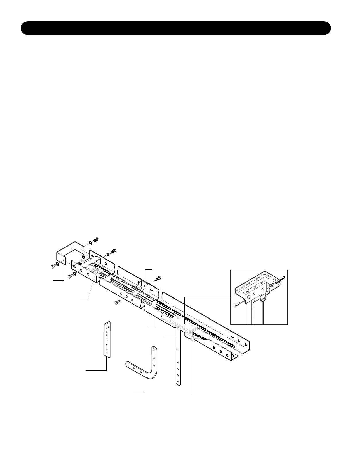
TRACK ASSEMBLY
1. Using the 3/8"-16 x 3/4 " bolts and flange hex nuts provided,
assemble the operator track by installing and tightening the
track spacer brackets. Position the spacers evenly over the
length of the track.
NOTE: The nylon pad on the spacer bracket should face up.
2. Using (2) 3/8"-16 x 3/4" bolts and flange hex nuts, install the
front idler assembly to the second set of holes of one end of
the track. Be sure the take-up bolt faces the front(toward door).
Refer to the illustration below.
3. Slide the trolley carriage onto the track so that the hole of the
door arm faces the front (towards door).
OPERATOR ATTACHMENT
1. Position the track assembly on the frame of the operator so
that the motor side of operator is in back (away from door ).
2. Align both the first and third holes from the end of the track
with holes located in the operator.
3. Connect the track to the operator by fastening four
3/8"-16 x 3/4" bolts and nuts through the frame and the end
holes in track. Tighten all four bolts to secure the track to
the operator.
© 2005, The Chamberlain Group, Inc.
01-12151C All Rights Reserved Printed in Mexico
INSTALLATION
Header
Bracket
Chain Tensioner
(Front Idler)
Door Bracket
Curved Arm
Track
Straight Arm
Refer To Instruction Manual
Provided With Operator For
Complete Mounting Instructions.
Spacer Bracket
Trolley Carriage
 Loading...