

Page 1
©
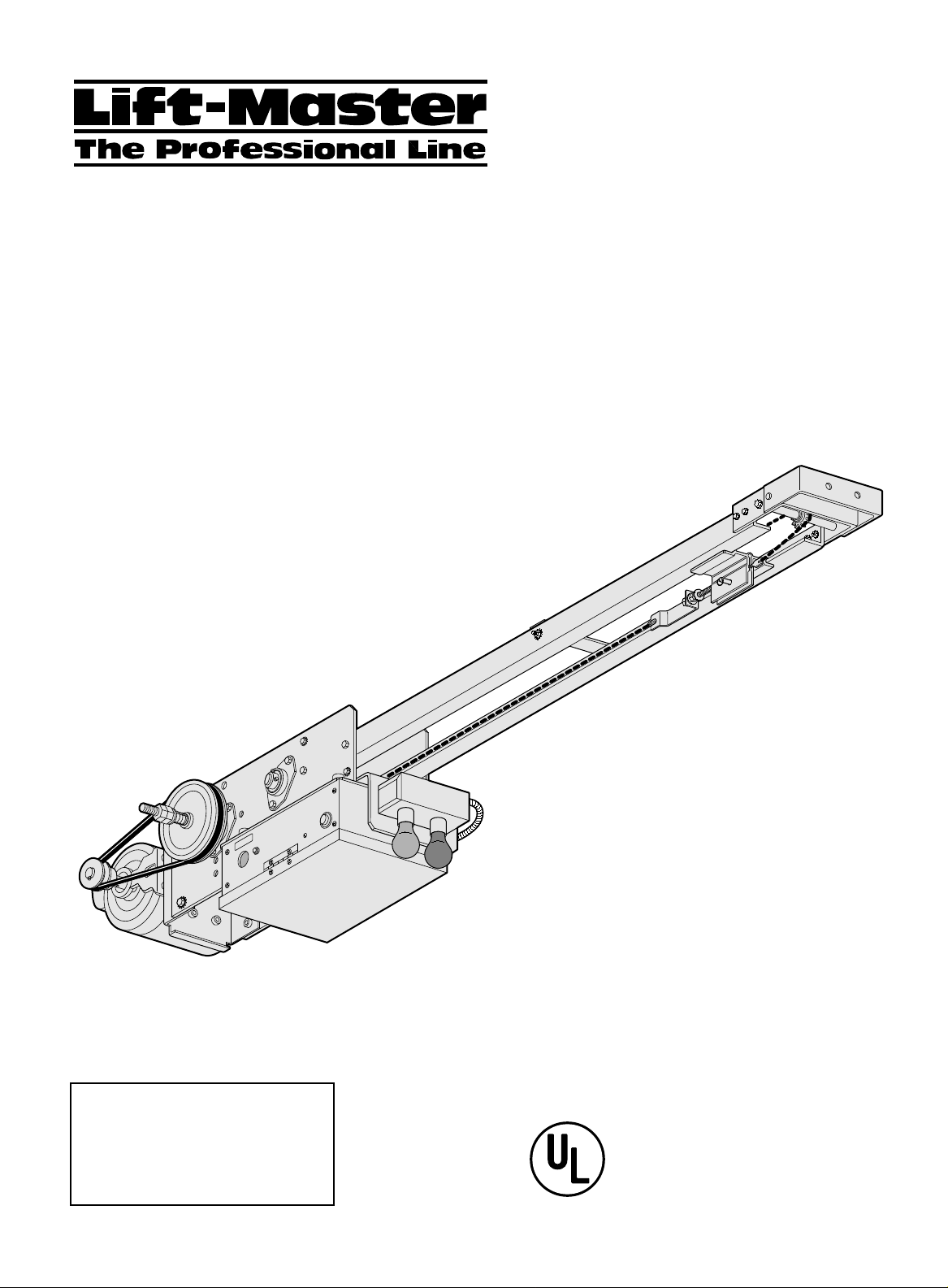
OWNER'S MANUAL
MODEL APT 211
SOLID STATE
HEAVY DUTY, HIGH CYCLE
BELT DRIVEN TROLLEY OPERATOR
The Chamberlain Group, Inc.
A DUCHOSSOIS ENTERPRISE
845 Larch Avenue
Elmhurst, Illinois 60126
Serial # ___________________
(located on electrical box cover)
Date of Installation __________
Wiring Type________________
COMMERCIAL DOOR OPERATOR
®
LISTED
NOT FOR RESIDENTIAL USE
Page 2
SPECIFICATIONS
MOTOR
(RESILIENT MOUNTING)
TYPE:...................................................Continuous duty
HORSEPOWER:.................................................1/2 Hp
Single phase
SPEED:.........................................................1725 RPM
VOLTAGE:........................................................115 Volt
CURRENT:........................................................10 AMP
MECHANICAL
DRIVE REDUCTION:
1st Reduction:....................Heavy duty (4L) V-Belt
2nd Reduction:................#48 Chain and sprockets
Output:................................................... #48 Chain
OUTPUT SHAFT SPEED:...........................144 R.P.M.
DOOR SPEED:..................................11" – 13" per sec.
BEARINGS:............................Heavy duty ball bearings
BRAKE: ......................... Optional solenoid drum brake
VIBRATION ISOLATION KIT.........................Standard
ELECTRICAL
CONTROL VOLTAGE:........................................5V dc
AUXILIARYVOLTAGE:.....................................24V dc
CONTROL STATION:.....................................3 Button
OPEN/CLOSE/STOP, NEMA 1
WIRING TYPE:.......................................B2 (Standard)
Momentary contact to OPEN/CLOSE/STOP plus
wiring for sensing device to reverse and auxiliary
devices to open and close with open override (other
types available. See chart.)
LIMIT ADJUST:..............Linear driven, fully adjustable
screw type cams. Adjustable to 22 feet.
SAFETY
DISCONNECT: ........................................Spring loaded
trolley disconnect arm
CLUTCH: ...................................Adjustable friction type
REVERSING EDGE:......................................(Optional)
Electric or pneumatic sensing device attached to the
bottom edge of door. Strongly recommended for
all
commercial operator installations.
when the 3 button control station is out of sight
of door or any other control (automatic or
manual) is used. See page 8.
Required
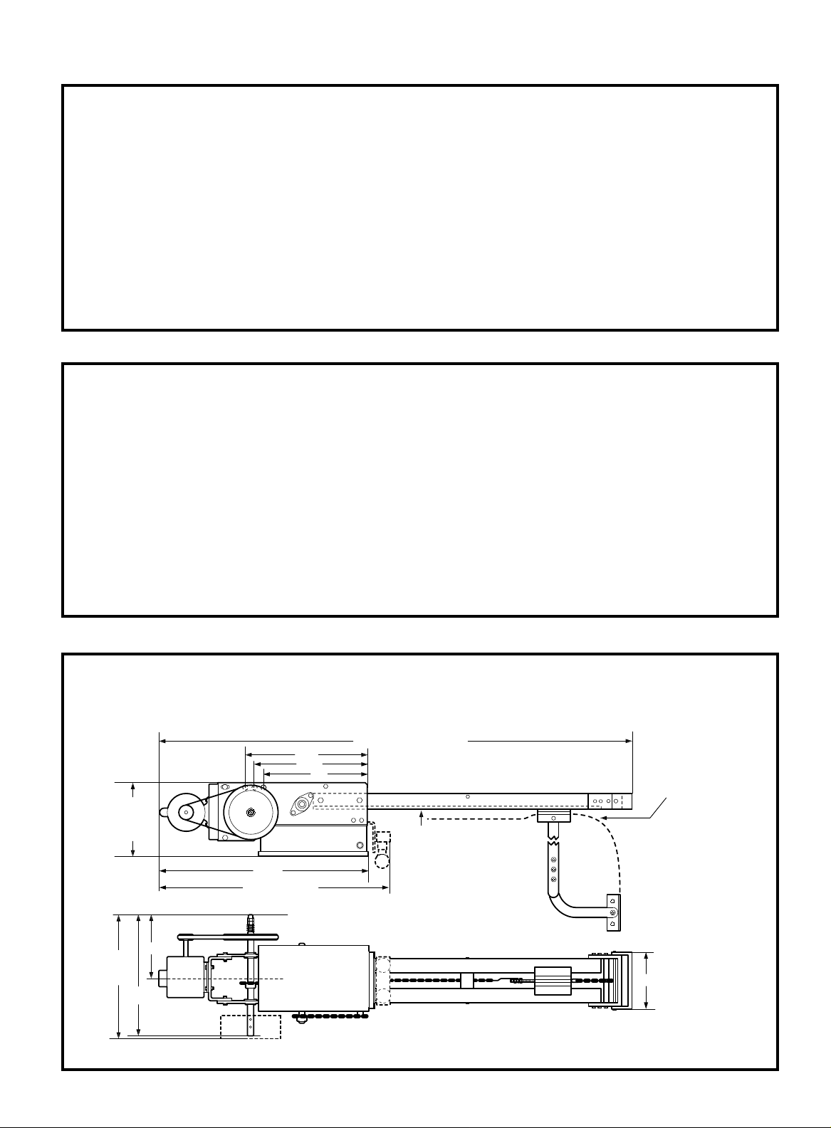
WEIGHTS AND DIMENSIONS
POWER HEAD WEIGHT .........55 LBS.
14.5"
13.75"
9.5"
with or
without
brake
27.4"
30" with light box
with
brake
16.1"
9"
C
L
16.25"
DOOR HEIGHT + 4' - 2 3/8"
13"
MIN. CLEARANCE OF 2"
FROM HIGH ARC OF DOOR
TO BOTTOM OF TRACK
7-1/2"
2
Page 3
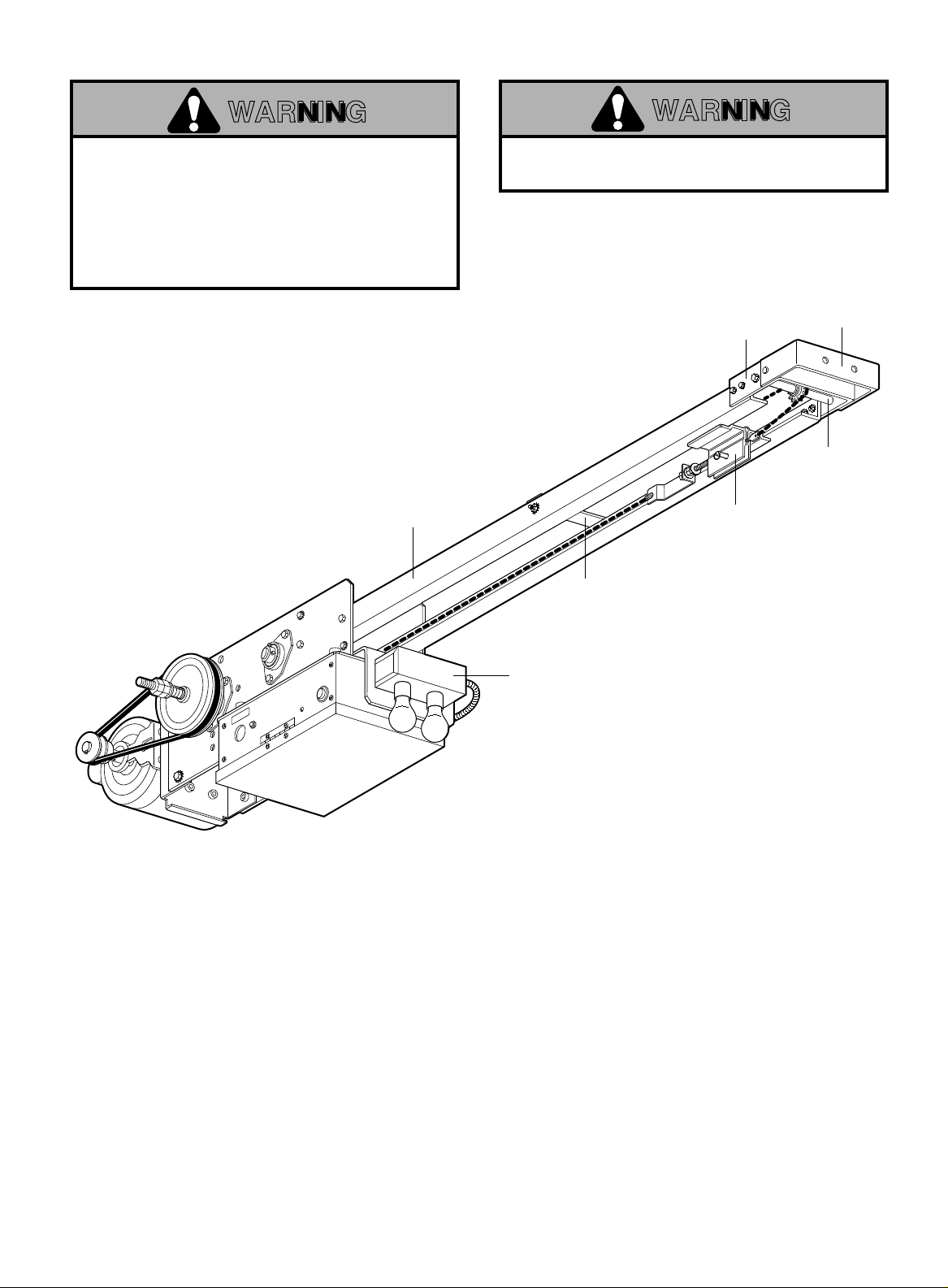
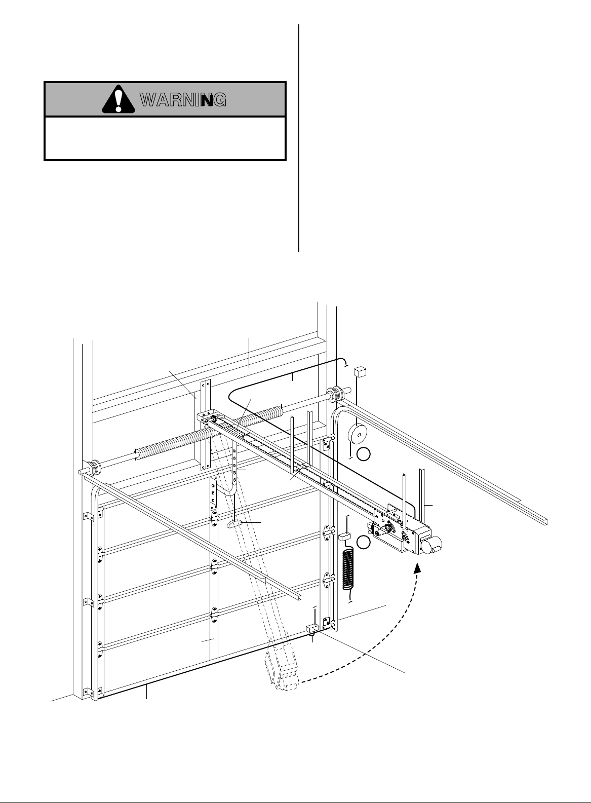
ASSEMBLE TRACK AND OPERATOR
Track
Track
Spacer
Trolley
Track Idler
Shaft
Header
Bracket
Idler Shaft
Bracket
Light Control
Module (Optional)
FIGURE 1
WARNING
KEEP DOOR BALANCED. STICKING OR BINDING
DOORS MUST BE REPAIRED. DOORS, DOOR
SPRINGS, CABLES, PULLEYS, BRACKETS AND
THEIR HARDWARE MAY BE UNDER EXTREME
TENSION AND CAN CAUSE SERIOUS PERSONAL
INJURY OR DEATH. CALL A PROFESSIONAL DOOR
SERVICEMAN TO MOVE OR ADJUST DOOR
SPRINGS OR HARDWARE.
WARNING
DO NOT CONNECT ELECTRIC POWER UNTIL
INSTRUCTED TO DO SO.
If possible, install the door opener 7 feet or more
above floor with the manual release handle
mounted 6 feet above the floor.
Check the identification tag mounted on the electrical
box to be sure the voltage, phase and h.p. are correct
for your needs.
1. Fasten track to the operator frame. DO NOT
TIGHTEN BOLTS. See Figure 1.
2. Position the trolley on the track. Attach track
spacer(s).
3. Place idler shaft bracket over end of track. There
are two holes on each side of bracket (Fig. 1).
Fasten shaft bracket to end of rail assembly.
4. Align track so that trolley moves easily and does
not bind. Tighten all bolts.
5. Run chain around front and rear sprockets and
attach to trolley assembly with master links. Adjust
chain only until excessive slack is removed. To
retain proper tension, tighten 3/8" lock nut.
3
Page 4
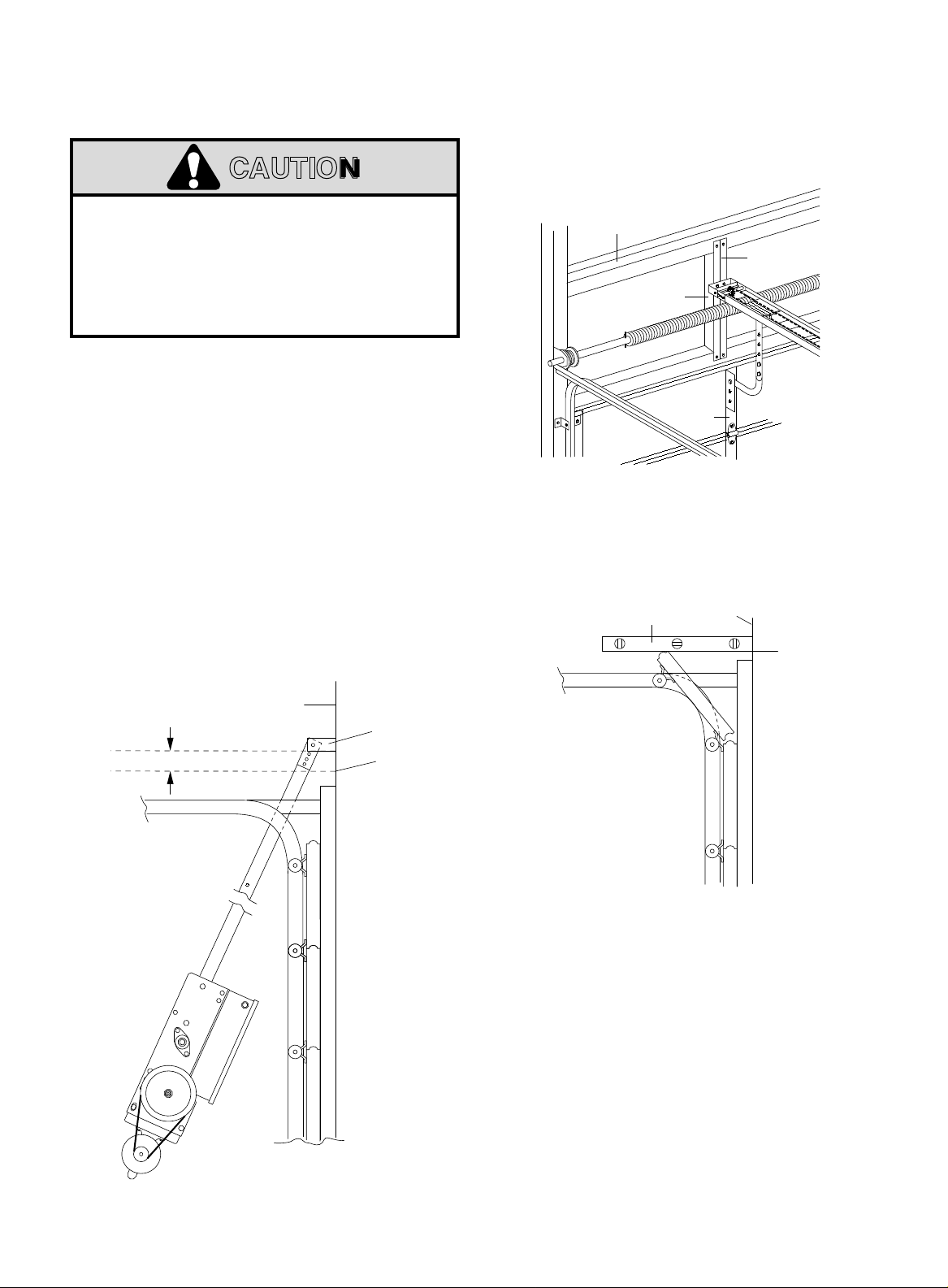
INSTALL OPERATOR
CAUTION: AT LEAST TWO PERSONS AND A STRONG, SAFE WORKING PLATFORM ARE
REQUIRED FOR THE INSTALLATION OF OPERATOR.
CAUTION
TO AVOID DAMAGE TO DOOR AND OPERATOR,
MAKE ALL DOOR LOCKS INOPERATIVE. SECURE
LOCK(S) IN "OPEN" POSITION.
IF THE DOOR LOCK NEEDS TO REMAIN
FUNCTIONAL, INSTALL AN INTERLOCK SWITCH.
DO NOT RUN THE OPERATOR BEFORE MAKING
LIMIT SWITCH ADJUSTMENTS.
FOR METAL BUILDINGS ONLY: A strong mounting
surface for the operator front header bracket is
needed. On the wall above the center stile, weld or
bolt a 2"x2"x1/4" piece of angle iron or another
suitable, heavy-duty material as shown in Figure 2.
6. Draw a vertical line on header (or reinforcement
material) above center stile of door.
7. Raise the door to its high arc point. Use a
carpenter's level to locate high arc point on wall
above door center stile as shown in Figure 3. Make
a horizontal line, intersecting the vertical centerline
mark.
FIGURE 4
URE 4
Header
2" Header
Wall
Bracket
High Arc
Point of Door
FIGURE 2
FIGURE 3
Building
Support
2"x 2"x 1/4"
Carpenter's
Angle Iron
Level
Vertical
Centerline
Center
Stile
Header
Wall
High Arc
Point
8. Close the door and refer to Figure 4. Position
operator chassis on the floor with the bottom edge of
header bracket 2" above horizontal mark and
centered on vertical line. Mark mounting holes.
FOR METAL BUILDINGS: Drill 3/8" holes for fastening
bolts. FOR CONCRETE BUILDINGS: Drill 3/8" holes
for anchor bolts, following manufacturer's instructions.
NOTE: Be sure header bracket is level before
tightening the bolts.
4
Page 5
9. Raise operator straight up until the door can be
raised to the full open position. See Figure 5.
Temporarily secure to ceiling or rafters with rope
or other suitable means.
WARNING
FAILURE TO SUSPEND THE OPERATOR
SECURELY MAY RESULT IN SERIOUS PERSONAL
INJURY OR DEATH, AND/OR PROPERTY DAMAGE.
10. Raise door to full open position. Place a 2x4
board on top of leading edge of door. Lower
operator to rest on 2x4 board.
Make four hangers from 2"x2"x1/4" angle iron. IT IS
RECOMMENDED THAT RAIL BE CENTERSUPPORTED AS WELL. Bolt the operator into place.
Building
Support
COIL CORD (OPTIONAL)
REFER TO (A) IN ILLUSTRATION
Connect operator end of coil cord to junction box (not
supplied) fastened to the wall approximately half-way
up the door opening.
Electrician must hardwire the junction box to the
operator electrical box in accordance with local
codes.
REEL (OPTIONAL)
REFER TO (B) IN ILLUSTRATION
Take-up reel should be installed 12" above the top of
the door.
2"x2"x1/4"
Angle Iron
Door
Bracket
Center
Stile
Trolley
Door
Arm
Wire 5V dc
Track
Spacer
Rope
Release
Air Hose
B
A
Hanger Angles
2"x2"x1/4"
Reversing
Edge
Pneumatic Air Switch
Not Required or Supplied
When Electric Reversing
Edge is Used
FIGURE 5
5
Page 6
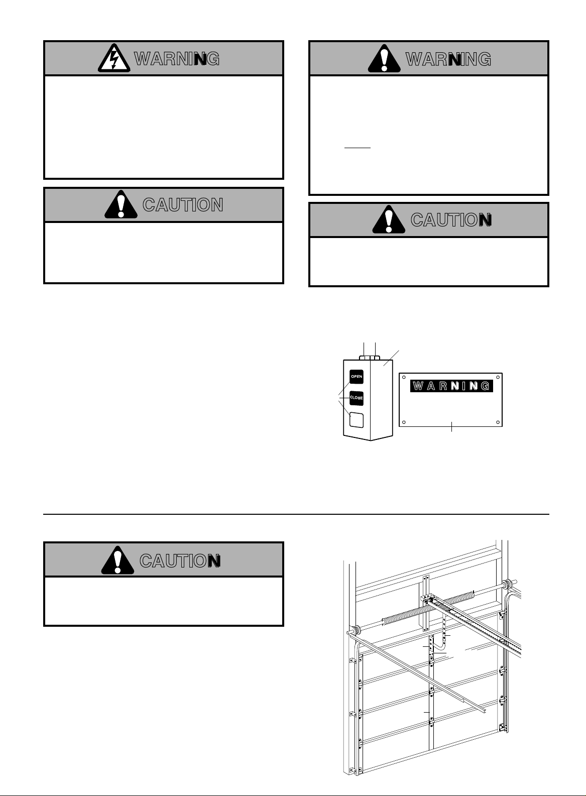
CONNECT OPERATOR TO POWER SUPPLY AND INSTALL CONTROL STATION
WARNING
DISCONNECT POWER AT THE FUSE BOX BEFORE
PROCEEDING.
OPERATOR MUST BE PROPERLY GROUNDED AND
CONNECTED IN ACCORDANCE WITH LOCAL
ELECTRICAL CODES. THE OPERATOR SHOULD BE
ON A SEPARATE FUSED LINE OF ADEQUATE
CAPACITY.
ALL ELECTRICAL CONNECTIONS MUST BE MADE
BY A QUALIFIED INDIVIDUAL.
INSTALL THE CONTROL STATION WHERE THE
DOOR IS VISIBLE, BUT AWAY FROM THE DOOR AND
ITS HARDWARE. IF CONTROL STATION CANNOT BE
INSTALLED WHERE DOOR IS VISIBLE, OR IF ANY
DEVICE OTHER THAN THE CONTROL STATION IS
USED TO ACTIVATE THE DOOR,
EDGE MUST
THE DOOR.
EDGE UNDER THESE CIRCUMSTANCES MAY
RESULT IN SERIOUS INJURY OR DEATH TO
PERSONS TRAPPED BENEATH THE DOOR.
BE INSTALLED ON THE BOTTOM OF
FAILURE TO INSTALL A REVERSING
WARNING
A REVERSING
CAUTION
TO AVOID DAMAGE TO DOOR AND OPERATOR,
MAKE ALL DOOR LOCKS INOPERATIVE. SECURE
LOCK(S) IN "OPEN" POSITION.
IF THE DOOR LOCK NEEDS TO REMAIN
FUNCTIONAL, INSTALL AN INTERLOCK SWITCH.
DO NOT ALLOW TROLLEY TO OVERRUN FRONT
IDLER SPROCKET OR RUN INTO OPERATOR HEAD.
LIMIT SWITCHES MAY NOT BE IN THE PROPER
POSITIONS. (See Limit Adjustments).
REFER TO MASTER WIRING DIAGRAM.
MAKE CONNECTION THROUGH THE 1-1/16" DIA. LABELED HOLE. DO NOT RUN CONTROL WIRES IN THE SAME
CONDUIT AS THE POWER WIRES.
11. Complete the electrical connections to operator and
control station (Refer to Control Connection Diagram,
Pg. 20). Fasten the control station to the wall.
FASTEN THE WARNING NOTICE BESIDE OR
BELOW THE PUSH BUTTONS.
Push
Buttons
OPEN
CLOSE
12. Apply power to operator. Press either the OPEN or
the CLOSE push button and observe direction of
STOP
trolley travel. Press the STOP button.
If trolley did not move in the correct direction, check
for improper wiring at control station or between
opener and control station.
If the operator is three phase and control station
wiring is correct, exchange any two of the three
incoming power leads.
If electrical problems persist, call our Toll Free number
(1-800-528-6563) for assistance.
13. Operate push button so that the trolley moves forward
(toward close position). Press STOP button when
trolley is approximately 10" from front wall.
CAUTION
Control Station
WARNING
TO PREVENT ENTRAPMENT
DO NOT START DOOR DOWNWARD
UNLESS DOORWAY IS CLEAR
WARNING Notice
CONNECT DOOR ARM AND BRACKET
CAUTION
REINFORCE CENTER STILE WITH A VERTICAL
BRACE. USE A PIECE OF ANGLE IRON THAT WILL
SPAN THE HEIGHT OF TOP PANEL. DO NOT CUT
HORIZONTAL STRUT.
14. With door CLOSED, snap door arm onto operator
trolley. Position door bracket against reinforced
center stile of top section of door. Make sure arm is
straight and centered on stile. Mark bracket holes.
Drill and fasten with 5/16" bolts.
NOTE 1: Choose a set of holes which aligns door
arm in a near vertical position.
NOTE 2: If door strut interferes with placement of
door bracket, position bracket below strut. DO NOT
CUT OR MODIFY STRUT.
Attach door arm to door bracket using 3/8"-16x1" screw
and lock nut.
Trolley
Door
Bracket Reinforcement
Center Stile
6
Door Arm
Brace
Page 7

EMERGENCY DISCONNECT SYSTEM
DOOR ARM IS RELEASED FROM TROLLEY
WHEN EMERGENCY DISCONNECT OPENS.
TO AVOID BEING STRUCK BY DOOR ARM, DO
NOT STAND UNDER THE ROPE OR DOOR ARM
Trolley
Track
WHEN PULLING THE EMERGENCY RELEASE.
WARNING
Header
Bracket
Emergency
Disconnect
Door
Bracket
12B0407
Door
Clevis
Pin
Straight
Door Arm
Assembly
1C3681
Curved
Door Arm
178B0045
NOTICE
Chain
Emergency
Release Handle
ADJUST LIMITS
WARNING
TO AVOID SERIOUS PERSONAL INJURY OR DEATH
FROM ELECTROCUTION, DISCONNECT ELECTRIC
POWER BEFORE MANUALLY MOVING LIMIT NUTS.
OLS
Open Limit
Switch
Actuator
Close Limit
Switch
Actuator
CLS
SLS
CLOSEOPEN
Emergency
Disconnect
TO DISCONNECT
DOOR FROM OPENER
Pull emergency release handle
Door Arm
straight down. Emergency
disconnect will open.
Emergency
Disconnect
Door Arm
Lift free end of door arm to trolley.
TO RECONNECT
DOOR ARM TO TROLLEY
Pull emergency handle to allow arm
to engage clevis pin. Release handle.
Emergency disconnect will close.
MAKE SURE THE LIMIT NUTS ARE POSITIONED
BETWEEN THE LIMIT SWITCH ACTUATORS
BEFORE PROCEEDING WITH ADJUSTMENTS.
1. Depress open limit switch. The operator should
stop.
2. To increase door travel, spin nut away from
actuator. To decrease door travel, spin limit nut
toward actuator.
3. Adjust open limit nut so that door will stop in open
position with the bottom of the door even with top
of door opening.
4. Repeat Steps 1 and 2 for close cycle. Be sure
close limit actuator is engaged as door fully seats
at the floor.
If other problems persist, call our toll-free number for
assistance - 1-800-528-6563.
Close Limit
Nut
Travel Nut
Retainer
Open Limit
Nut
Press Travel Nut Retainer
Down Toward Frame
TO DISENGAGE.
7
Page 8

ADJUST CLUTCH
Adjust clutch so that it is tight enough to open and
close the door but will slip when the door meets an
obstruction. Either loosen or tighten the clutch nut
with 1/4 turn increments. The clutch will require
periodic inspection and adjustment.
CAUTION: The adjustable friction clutch is NOT
an automatic reversing device. An electric or
pneumatic reversing edge can be added to
bottom edge of door if desired.
CONNECT REVERSING EDGE DEVICE (OPTIONAL)
WARNING
IF CONTROL STATION CANNOT BE INSTALLED
WHERE DOOR IS VISIBLE, OR IF ANY DEVICE OTHER
THAN THE CONTROL STATION IS USED TO ACTIVATE
THE DOOR,
ON THE BOTTOM OF THE DOOR.
A REVERSING EDGE UNDER THESE CIRCUMSTANCES
MAY RESULT IN SERIOUS PERSONAL INJURY OR
DEATH TO PERSONS TRAPPED BENEATH THE DOOR.
A REVERSING EDGE MUST BE INSTALLED
FAILURE TO INSTALL
Clutch Pad
Clutch Plate
Jam Nut
Adjusting Nut
Spring
Washer
Clutch Pulley
The operator has been pre-wired to accept
connection of a reversing edge device (Figure 5,
Page 5). Connect the normally open contacts to
terminals T4 and T8 on the low voltage terminal
block. A cut-off switch will de-activate the safety
device during the last few inches of the door's
downward travel.
MAINTENANCE SCHEDULE
Check at the intervals listed in the following chart.
EVERY EVERY EVERY
ITEM PROCEDURE 3 MONTHS 6 MONTHS 12 MONTHS
Drive Chain Check for excessive slack.
Check & adjust as required.
Lubricate.*
Sprockets Check set screw tightness ●✔
Clutch Check & adjust as required ●✔
Belt Check condition & tension ●✔
Fasteners Check & tighten as required ●✔
Manual Disconnect Check & Operate ●✔
Bearings & Shafts Check for wear & lubricate ●✔
✳ Use SAE 30 Oil (Never use grease or silicone spray).
✔ Repeat ALL procedures.
■ Do not lubricate motor. Motor bearings are rated for continuous operation.
●✔
■ Do not lubricate clutch or V-belt.
■ Inspect and service whenever a malfunction is observed or suspected.
■ CAUTION: BEFORE SERVICING, ALWA YS DISCONNECT OPERATOR FROM POWER SUPPLY.
8
Page 9

BRAKE INSTALLATION & ASSEMBLY PARTS
HTL/APT Shown
APT Bearings Shown.
Models HTL and APT
Brake Installation Identical
WARNING
A
Cotter
Pin
TO AVOID SERIOUS PERSONAL INJURY OR DEATH
FROM ELECTROCUTION, DISCONNECT ELECTRICAL
POWER TO OPERATOR BEFORE PROCEEDING.
1. Install brake drum on clutch pulley shaft as
illustrated in Fig. A.
2. Attach the three spacers provided to back of brake
assembly housing using three 5/16 x 5/8 sems
screws (Figs. B and C).
3. Push brake lever engaging nylon stud release
between brake shoes and align brake drum
between brake shoe assembly (Fig. B).
4. Adjust spring loaded bolt on brake shoe assembly
so that spring is compressed to 1".
5. Mount brake assembly housing with spacers
attached to operator frame using three 5/16 x 5/8
sems screws (See Fig. B).
6. Remove plug from 7/8" hole in electrical box and
attach conduit assembly.
7. Connect wires per master wiring diagram.
8. Reconnect power to the operator.
9. Test for proper brake operation and replace brake
cover.
ADJUSTMENT: The brake assembly is selfadjusting and should not require further
adjustment.
3/4" Washer
to Disengage Brake
Nylon
Stud
Release
5/16" x 5/8"
SEMS Screw
3/4" Washer
Brake Drum
Push Brake Lever
Shoe Assembly
Brake Shoe
Assembly
1
B
Brake
Drum
2
Pulley Shaft
Cotter
Pin
Spacer
Clutch
5/16" x 5/8"
SEMS Screw
Operator
Frame
C
11
REPAIR PARTS FOR BRAKE ASSEMBLY
ITEM PART NO. DESCRIPTION & QUANTITY
1 17D111 Brake Box (1)
2 204B118 Solenoid 115V (1)
204B118-1 Solenoid 230V (1)
3 113B49 Brake Lever Pivot (1)
4 179A46 Brake Release Stud
5 142A143 Brake Stud Plate (1)
6 1B4421 Brake Shoe Assy. (2)
12
8
3
4
7
6
5
ITEM PART NO. DESCRIPTION & QUANTITY
7 60B31 Brake Drum (1)
8 179B45 Brake Pivot Stud (3)
9 184A111 Brake Spacer (3)
10 1B4726 Conduit Assy. H-Series (1)
11 31D387 Cover (1)
12 31A388 Dome Plug (1)
9
9
10
Page 10

SOLID STATE SINGLE PHASE
WIRING DIAGRAM
OPEN
NC
White
Gry./Wht.
2
Yellow
Red
Yellow
3
Blue
Brown
1
RADIO CONTROL
LIMIT
SWITCH
C
POWER
INDUCTOR
Yellow
Red
White
Blue
NO
P7-
Remove Jumper
to Install Interlock
Blue
White
Blue
White
Yellow
Red
Black
E10
P1-
15
P6-
E12
Q7
E8
E9
P3-
P2-
U1
4
12345678910
TB1-
1
Open / Close
Orange
Q8
E14
E11
234
1
ON
Open
Close
Sensing Device
Yellow
White
Red
Q9
E13
P4-
OFF
Stop
White
E16
E17
NC
NO
Red
White
White
Q10
E15
E1
E2
E3
SENSING
SWITCH
E20
E19
LIMIT
C
NC
NO
Yellow
Orange
White
Q11
E18
N
L1
H
L3 L2
E4
E21
XMFR SECONDARY
CLOSE
LIMIT
SWITCH
C
*
Black
Black
Red
White
Black
White White
Neutral 115V
208-230V, 1Ø
Hot 115V
208-230V, 1Ø
Black
Black
Blue
Yellow
E6 E7
Yellow
Black
Black
Black
Black
Black 115V
Orange 208-230V
Blue
Blue
Yellow
Internal Interlock
(when used)
OVERLOAD
PROTECTOR
Blue
MOTOR
*THIS WIRE NOT USED
WITH POWER INDUCTOR
RedRedRed
OrangeOrange
TO
MECHANICAL
BRAKE
GND
White
Orange 115V
Black 208-230V
LINE
TRANSFORMER
LOAD
10
Page 11

STANDARD POWER AND
CONTROL CONNECTION DIAGRAM
(Solid State Board CDO - 115V, 208-230V, 1Ø)
123
RADIO CONTROL
(24V dc only)
TB1-
Remove Jumper
to Install Interlock
12 345678 910
Open
Close
Open / Close
Stop
Sensing Device
L1 N
L2 H
L3
GND
Neutral 115V, 208-230V, 1Ø
Hot 115V, 208-230V, 1Ø
The Chamberlain Group, Inc.
1Ø Standard Power & Control Connection Diagram
Solid State CDO
2/22/94 - 2/25/94
11
Page 12

NOTE: This equipment has been tested and found to comply with the limits for a Class A digital device, pursuant to Part 15 of the FCC Rules.
These limits are designed to provide reasonable protection against harmful interference when the equipment is operated in a commercial
environment. This equipment generates, uses, and can radiate radio frequency energy and, if not installed and used in accordance with the
instruction manual, may cause harmful interference to radio communications. Operation of this equipment in a residential area is likely to
cause harmful interference, in which case the user will be required to correct the interference at his own expense.
MEMO:
12
Page 13

MEMO:
OPTIONAL SETTINGS
Set Maximum Run Timer
Begin with door in closed position. Set dip switch to max. run timer
mode. Press control station open button to operate door from closed to
full open position without stopping. Set dip switch to desired operating
mode (B2, C2, D1, E2, T, TS).
Set Adjustable Mid Stop
Begin with door in closed position. Set dip switch to adj. mid stop mode.
Press control station open button to operate door from closed to mid
stop position and stop with control station stop button. Set dip switch to
desired operating mode (B2, C2, D1, E2, T, TS).
Set Timer to Close (NOTE: Requires P/N 1A4811 CPSII Option
Board with Timer to Close Function)
Set dip switch to timer to close mode. Momentarily press control station
open button to set timer duration in 5 second increments. (Red
diagnostic L.E.D. will flash to indicate the entry of each 5 second
increment into memory). To re-set timer memory to zero, press control
station close button. Set dip switch to (T or TS) operating mode after
timer is programmed.
Diagnostic Mode
Set dip switch to diagnostic mode. Flashing red diagnostic L.E.D.
indicates proper microprocessor function. If the diagnostic L.E.D. does
not light, the control logic board requires replacement.
Set
max.
run
timer
Set
adj.
mid
stop
Set
timer
to close
Diagnostic
mode
123
OFF
123
OFF
123
OFF
123
OFF
4
4
4
4
13
Page 14

OPERATING MODE
TYPE STATION
B2 3 Button, 1 Button, 1 & 3 Button Radio Control
Function: Momentary contact to open, close and stop, plus wiring for
sensing device to reverse and auxiliary devices to open and close
with open override.
C2 3 Button, 3 Button Radio Control
Function: Momentary contact to open and stop with constant pressure
to close, open override plus wiring for sensing device to reverse.
D1 2 Button, 3 Button Radio Control
Function: Constant pressure to open and close with wiring for sensing
device to stop.
B2
C2
123
OFF
123
OFF
4
4
E2 2 Button, 3 Button Radio Control
Function: Momentary contact to open with override and constant
pressure to close. Release of close button will cause door to reverse
(roll-back feature) plus wiring for sensing device to reverse.
T* 3 Button, 1 Button, 1 & 3 Button Radio Control
Function: Momentary contact to open, close, and stop, with open
override and timer to close. Every device that causes door to open,
except a reversing device, activates timer to close. Auxiliary controls
can be connected to open input to activate the timer to close. If the
timer has been activated, the open button and radio control can
recycle the timer. The stop button will deactivate the timer until the
close button is used to close the door. (NOTE: Requires P/N 1A4811
CPSII Option Board with Timer to Close Function.)
TS* 3 Button, 1 Button, 1 & 3 Button Radio Control
Function: Momentary contact to open, close, and stop with open
override and timer to close. Every device that causes door to open,
including a reversing device, activates timer to close. Auxiliary
controls can be connected to open input to activate the timer to close.
If the timer has been activated, the open button and radio control can
recycle the timer. The stop button will deactivate the timer until the
close button is used to close the door. (NOTE: Requires P/N 1A4811
CPSII Option Board with Timer to Close Function.)
D1
E2
T
TS
123
OFF
123
OFF
123
OFF
123
OFF
4
4
4
4
NOTE:
1. External interlocks may be used with all functional modes.
2. Auxiliary devices are any devices that have only one set of
contacts. Examples are: photocell, loop detector, pneumatic or
electrical treadles, residential radio controls, one button stations,
pull cords, etc.
3. Open override means that the door may be reversed while closing
by activating an opening device without the need to use the stop
button first.
14
Page 15

NEMA MOTOR WIRING DIAGRAMS
The Chamberlain Group, Inc.
NEMA Motor Wiring Diagrams
2/19/94
Motor
Cable
Motor
T2 White
T4 YellowYellow
115V
Blue
Yellow
Orange
SINGLE VOLTAGE
1/3 & 1/2HP 115V only
115V
T1 - BlueBlack
T4 - Yellow
T5 - Black
T8 - RedRed
1 PHASE
208-230V
Motor
T4 YellowOrange
Orange
Blue
Black
Red
Cable
Motor
Yellow
Black
Blue
Orange
Red
T5 Black
T3 Orange
T1 Blue
T8 Red
Black
Cable
Yellow
Blue
Red
T5-Black
T1 Blue
3 PHASE
1/3 & 1/2HP 3/4HP & OVER
Motor
Yellow
Black
Blue
Orange
Red
T1
T7
T2
T8
T3
T9
P2
P1
T7
T2
T8
T3
208-230V
T1
T4
T5
T6
T9
T8
RedT3Orange
T2
White
208-230V
T4
T5
T6
Cable
DENOTES WIRENUT CONNECTION
Cable
15
Page 16

ILLUSTRATED PARTS - SOLID STATE ELECTRICAL BOX
8
18
12
2
21
17
16
11
3
11
6
10
19
20
15
13
14
13
7
3
22
4
WIRING
CONTROL
1
2
NEC CLASS 2 CIRCUIT
3
9
1
5
16
Page 17

ELECTRICAL BOX PARTS LIST
FOR
APT 211 SOLID STATE
ITEM
PART NO. QTY. DESCRIPTION
NO.
1 1B3727 1 Terminal Assy. 3-Lug
2 41K4304 1 Switch Bracket Assy. (Aux. & Sensing)
3 1B3796 1 Limit Shaft-Sprocket Assy.
4 1B4681 1 Cover & Hinge Assy.
5 1C4691 1 Electric Box Assy.
6 1B4683 1 Wire Harness Limit Switch
7 11A012 1 Flanged Sleeve Bearing
8 12B552 1 Limit Bracket
9 31A388 1 Dome Plug
10 155B16 1 Heat Sink
11 133A182 2 Limit Nut 1/2"
12 171A411 4 Screw 4/40 x 1-1/2" Pan Head
13 216A184 2 Thrust Washer
14 216A191 1 Washer, Spring Curved
15 158A49 1 Retaining Ring 3/8"
16 184A109 4 Spacer - Stand Off - Round
17 180B133 2 Limit Switch
18 1D4650 1 PCB Assy.
19 180B159-4 1 Overload 10A
20 204B134 1 Transformer 115/230V
21 1B4682 1 Radio Control Harness
22 1B4824 1 Inductor Power Assembly
17
Page 18

ILLUSTRATED PARTS - OPERATOR MODEL APT 211
11
14
8
9
8
20
9
18
17
5
19
15
10
13
13
16
12
15
18
4
3
18
7
7
8
6
5
2
1
Page 19

19
REPAIR PARTS FOR MODEL APT 211
ITEM
NO. PART NO. QTY DESCRIPTION
1 1 Electrical Box Assy. (See detail)
2 1B4684 1 Motor Cable Assy.
3 123D141 1 Motor 1/2 hp 115V 1 Phase
4 1C4707 1 Motor Mounting Bracket Assy.
5 1A3742 2 Chain Assy. (43 Pitches)
6 81C172 1 Sprocket-10T
7 See Chart 2 L-Rail
8 1B4001 1 Trolley Assy.
9 1C3992 1 Bracket Assy.
10 1B4698 1 Clutch Shaft Assy.
11 184D106 Varies Spacer - Rail #48 Chain
12 144B44 1 Pulley 7" - 4L
13 41K4615 2 Ball Bearing Kit
14 1B4697 1 Shaft Assy. - Output
15 41K4301 1 Clutch Assy. Kit
16 20B12 1 V-Belt 30" - 4L
17 144A43 1 Pulley 1-5/8" - 4L
18 59D54-2 1 Frame Rt. Side
59D54-1 1 Frame Lt. Side
19 184B97 1 Spacer
20 41K4302 1 Header Bracket Assy.
HOW TO ORDER REPAIR PARTS
OUR LARGE SERVICE ORGANIZATION
SPANS AMERICA
INSTALLATION AND SERVICE INFORMATION
ARE AVAILABLE 6 DAYS A WEEK
CALL OUR TOLL FREE NUMBER - 1-800-528-6563
HOURS 7:00 TO 3:30 p.m. (Mountain Std. Time)
MONDAY through SATURDAY
IN CANADA
CALL OUR TOLL FREE NUMBER – 1-800-654-4736
WHEN ORDERING REPAIR PARTS
PLEASE SUPPLY THE FOLLOWING INFORMATION:
PART NUMBER DESCRIPTION MODEL
NUMBER
ADDRESS ORDER TO:
THE CHAMBERLAIN GROUP, INC.
Electronic Parts & Service Dept.
2301 N. Forbes Blvd., Suite 104
Tucson, AZ 85745
ITEM #7 ITEM #11
Door Chain #48 Chain 1 Set
Hts. Rail Qty. Assembly Qty. Master Link Qty. Spacer Kit Qty.
8 Feet 183C0137 2 1A4765-1 1 1A0995 1 1A4004 2
10' 183C0137-1 2 1A4765-2 1 1A0995 1 1A4004 2
12' 183C0137-2 2 1A4765-3 1 1A0995 1 1A4004 2
14' 183C0137-3 2 1A4765-4 1 1A0995 1 1A4004 3
16' 183C0138 2 1A4765-5 1 1A0995 1 1A4004 3
18' 183C0138-1 2 1A4765-6 1 1A0995 1 1A4004 3
20' 183C0138-2 2 1A4765-7 1 1A0995 1 1A4004 4
22' 183C0138-3 2 1A4765-8 1 1A0995 1 1A4004 4
Page 20

CONTROL CONNECTION DIAGRAM
ATTENTION: The 3-Button Control Station provided must be connected for operation.
3 BUTTON STATION OR 3 POSITION KEYSWITCH WITH SPRING RETURN TO CENTER AND STOP BUTTON
STANDARD
7645
Open
Close
Stop
2 BUTTON STATION OR 3 POSITION KEYSWITCH WITH SPRING RETURN TO CENTER
STANDARD
764
7645
2 OR MORE KEY LOCKOUT
Open
Close Close
Stop Stop
Open
2 OR MORE
764
®
7645
Open
Close
Stop
Keyswitch
D1 & E2
Open
Close
1 BUTTON STATION OR ANY AUXILIARY DEVICE
OPEN / CLOSE
14
SENSING DEVICE TO REVERSE OR STOP EXTERNAL INTERLOCK
48
MODE ONLY
B2, T & TS
MODE ONLY
Open
Close Close
RESIDENTIAL RADIO CONTROLS
OPEN TIMER TO CLOSE
RADIO CONTROL
REMOVE JUMPER
23
Open
4110
123
(24Vdc only)
D1 & E2
MODE ONLY
23
ONE
WIRING TYPES - ALL
2 OR MORE
© 1995, The Chamberlain Group, Inc.
114A1797C All Rights Reserved Printed in Mexico
 Loading...