

Page 1
1
CENTER MOUNT MODIFICATION
For Use With GH Operator
659001
PART # DESCRIPTION QTY
Instructions 1
10-10882 Chain Guard 1
11-5220 20' Cold Rolled Steel. 1" Round Bar 1
12-11438 Bearing 2
Nylon Shaft Collar 1" (Rework) 1
15-48B14LXX Sprocket #48B14 1" Bore 1
19-40013 Roller Chain #40, 13 Pitches 1
19-40ML Masterlink #40 1
75-10733 Chain Wheel 1
Eye Bolt 5/16-18 X 3-1/4" 2
Cable Clamp 2
80-206-10 Spacer 1-1/32 X 1-1/2 X 1/64 5
80-206-11 Spacer 1-1/16 X 1-1/2 X 1/16 5
86-RP08-108 Long Roll Pin 1/4 X 1-1/2" 1
86-RP10-208 Long Roll Pin 5/16 X 2-1/2" 2
86-RP10-100 Long Roll Pin 5/16 X 1" 2
Cable 1/16" 1
Sash chain-12' 1
APPLICATION
This modification is available for model GH operators. For use on
sectional doors only.
FUNCTIONS
This allows emergency hoist access to either side of the door.
Must be factory supplied with operator.
PREPARATION
We have set up the handing of the chain hoist based on your
order. If you find due to the job conditions that the chain hoist
needs to be on the opposite side of the operator, it can be moved.
If this is the situation, do this modification before mounting the
operator. Refer to the operator owner’s manual.
PACKING LIST
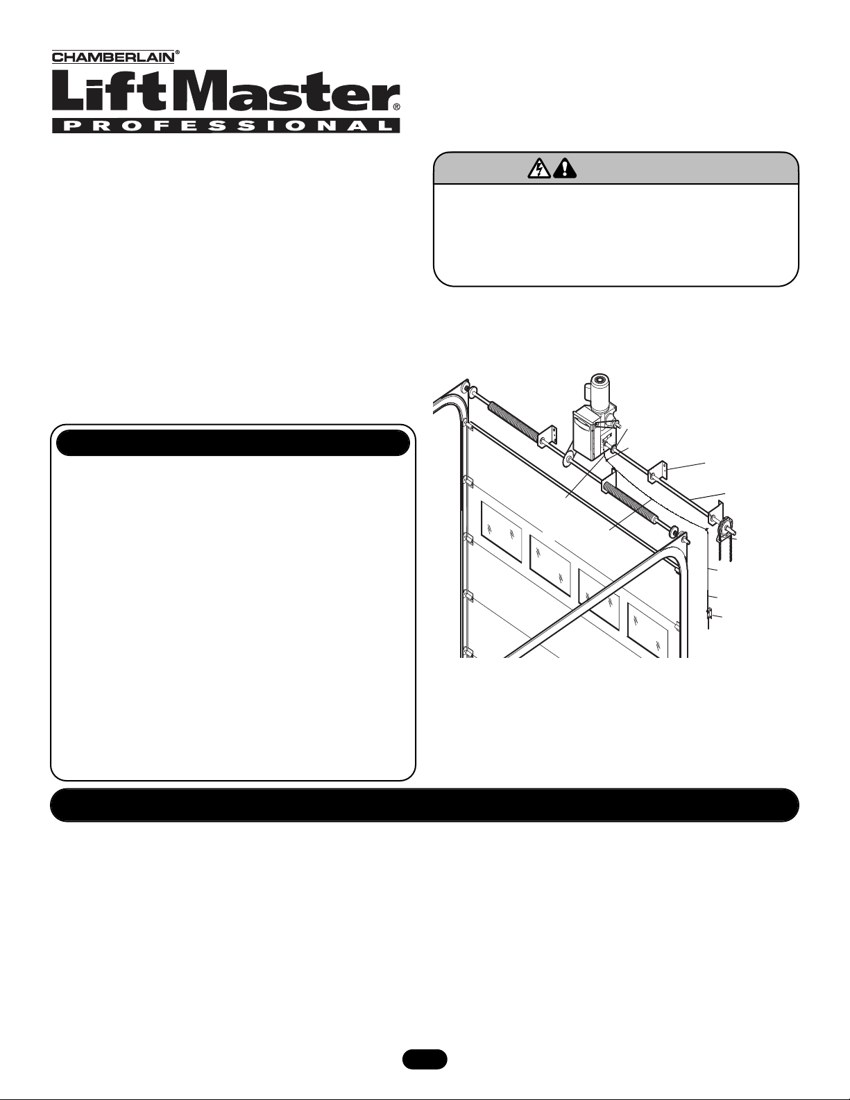
NOTE: Chain hoist shown on right, drive shown on left.
FIGURE 1
INSTALLATION
1. Install the driven sprocket on the door shaft and mount the
operator based on the location of this sprocket. If necessary
cut the unused side of the hand chain shaft off so that the drive
chain does not interfere with the operator mechanism.
2. This kit includes a length of cold rolled 1" shaft that is half the
door width plus 2' based on a center mounted door operator.
Be sure that this is long enough for your application. If not,
secure a longer shaft before continuing. Install the 48B14
sprocket provided on the end of the shaft by drilling a 1/4" hole
through the sprocket and shaft and secure with the 1/4" by
1-1/2" long roll pin provided. Be sure that the shaft does not
extend past the end of the sprocket and that the teeth of the
sprocket are at the end of the shaft (Figure 2).
To prevent possible SERIOUS INJURY or DEATH, disconnect
electric power to operator BEFORE installing.
ALL installations and electrical connections MUST be made by
a qualified individual.
WARNING
WARNING
3. Raise the shaft and sprocket assembly into position so that this
sprocket is butted against the sprocket on the operator hand
chain shaft and support the shaft temporarily. Use the piece of
#40 chain provided to connect the two sprockets together.
4. Slide bearing onto the shaft and securely mount it so that the
shaft turns freely without binding.
5. Use the instructions below to complete the assembly of the
chain hoist.
CENTER MOUNT GH MODIFICATION
Sprocket and Chain Two Identical
#48 Sprockets Butted Together and
Wrapped With #40 Chain (Figure 2).
Screw Eye
Bearing Assembly
Sash Chain
Cable Extension
Extension Shaft
Cable Extension
Sash Chain
Chain Retaining
Bracket
Chain Hoist
Page 2
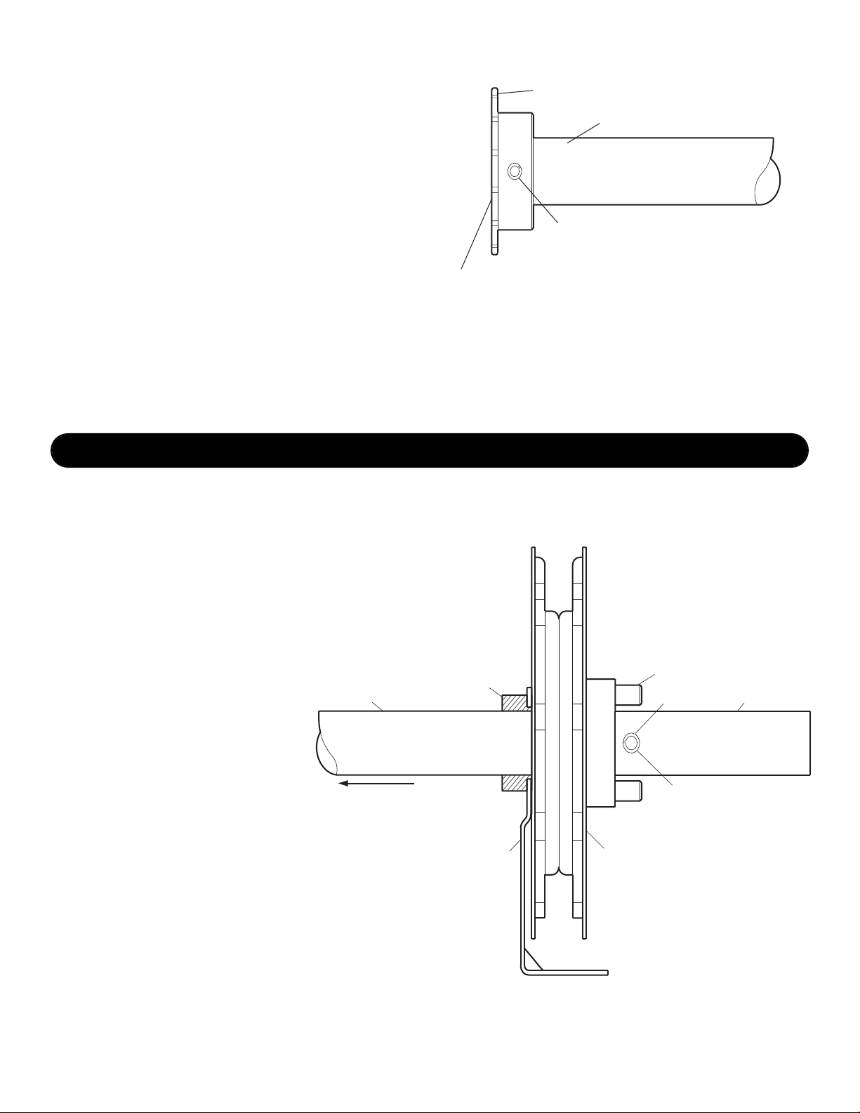
FIGURE 26. Cut off the excess shaft if necessary but allow for another
bearing on the outside of the chain hoist to support the load
when the hoist is used.
7. Install the second bearing.
8. Cut the disconnect sash chain close to the operator and splice
in the cable provided with a cable clamp (provided). Run the
cable through screw eyes and down the wall under the chain
hoist. Use the other cable clamp to reattach the sash chain to
this cable. It is necessary to have chain at the floor end of the
cable so that the hand chain engagement mechanism can be
locked down with the chain retaining bracket.
CHAIN HOIST INSTALLATION
1. Determine location for the hand chain assembly. Slide the 1"
shaft collar on the shaft, reworked side toward the end of the
shaft, and tighten down.
2. Starting against shaft collar, slide the chain guide on the end of
the shaft collar that has been reworked. Slide the chain wheel
assembly on next.
3. Install (2) 5/16" x 1" long roll pins in the holes in the chain
wheel hub.
4. Drill a 5/16" hole next to the hub on the chain wheel assembly
and install a 5/16" x 2-1/2" roll pin. Do not make
the assembly too tight. Thick and thin
washers are provided to take out extra
slack or to allow more movement.
FIGURE 3
© 2005, The Chamberlain Group, Inc.
01-12500B All Rights Reserved Printed in Mexico
48B14 Sprocket 1" Bore
Extension Shaft 1" Diameter Cold Rolled Steel
Drill 1/4" Hole -Through Pin With 1/4"x1-1/2" Roll Pin
Sprocket Teeth at End
of Shaft. Do Not Let Shaft
Protrude Beyond End
of Sprocket.
Extension Shaft
Towards Operator
1" Shaft Collar
(Reworked)
Chain Guard
Roll Pin 5/16"x1" Long
Drill 5/16" Hole
Roll Pin
5/16"x2-1/2" Long
Chain Wheel Assembly
Free End of Shaft
 Loading...