


TR1200I

TR800 / TR1200i
Folding Treadmill
Owners Manual
For safe use and product knowledge, please
completely read this Product OWNERS MANUAL.
v. 1.2


TR800 / TR1200i
Folding Treadmill
Welcome to LifeSpan
Congratulations in taking a step forward to increase your level of physical activity or add
variety to your current exercise program. Physical activity is now more than ever a necessity
to keep your body healthy and fit. Whether your motivation is to Lose Weight, manage a
Chronic Disease like diabetes, train for a sporting event or just live a Healthy Lifestyle,
LifeSpan products can help you achieve your health and fitness goals.
In this manual we have included exercise information that is specific to each of these 4 key
motivations for exercise. We also invite you to the LifeSpan Fitness website at
www.LifeSpanfitness.com where we include additional information and tools to help you
maintain your exercise program and achieve your health and fitness goals.
ers who say they prefer to exercise in the comfort and privacy of their own homes. Each
Home series product is designed and manufactured to exceed your expectations for quality
and durability, simple assembly and ease of operation.
Please read this manual thoroughly before assembly and operation of your new LifeSpan
equipment. It includes information on proper operation, safety precautions, product assembly and ongoing maintenance.
Remember that some types of service should only be performed by a qualified service technician. In the instance that service is required, please contact your authorized LifeSpan
retailer or log on to our website and select the Customer Support option. Complete the inform
tion requested and we will respond to your inquiry within 1 business day.
PCE Health and Fitness
PO Box 981316
Park City, Utah 84098-1316
Phone: 801.973.9993
Fax: 801.973.9923
www.lifespanfitness.com
Neither PCE Health and Fitness nor its representatives can accept responsibility for any
damages or injury incurred as a result of information presented in this manual except under
the terms of the product warranty.

Welcome
3
5
Limited Home Use Warranty
Important Safety Precautions
Assembly Instructions
Console Overview
Treadmill Operations
Innovative Features
Program Overview
Belt Lubrication and Treadmill Maintenance
Belt Tensioning and Alignment
Moving and Storage
6
7
9
15
18
21
22
30
31
32
Troubleshooting
Engineering Mode
Extended Warranty
Serial Number Information
34
35
39
40

TR800 / TR1200i
Folding Treadmill
TR800
Workout Time, Calories,
Distance, Heart Rate, Speed,
Incline
Blue backlit LCD
15 Rows by 20 Columns
Manual, Preset (17), User Set-up
(2), Heart Rate Control (2)
Grip Pulse
TR1200i
Date and Time, Workout Time,
Calories, Step Count, Distance,
Heart Rate, Speed, Incline
Multi-Color LCD
15 Rows by 20 Columns
Manual, Preset (17), User Set-up
(2), Heart Rate Control (2)
Audio Center with in / out jacks
and integrated speakers
Grip Pulse with Receiver
(chest strap not included)
Speed Range
Incline Levels
Running Belt Size
Roller Size
Deck
Drive Motor
Lift Motor
Maximum User Weight
Dimensions
Motor
.6 - 10
0 - 12
18” x 52”
2.0“ tapered
.75” Phenolic Deck with 8 Bumper
Suspension
1.75 HP Continuous Duty DC
Motor
650 lb. Max Lift Rating
275 lbs
67” L x 31” W x 54” H
1 3
.5 - 11
0 - 15
20” x 56”
2.5” tapered
1” Phenolic Deck with 8 Bumper
Suspension
2.5 HP Continuous Duty DC
Motor
800 lb. Max Lift Rating
300 lbs
71” L x 34” W x 54” H

TR800 and TR1200i Folding Treadmills
Treadmill
TR800 TR1200i
Lifetime
Motor:
1
The customer may be responsible to pay for the Service Technician’s travel time where travel in excess of
20 miles is required.
Lifetime
3 Years
1 Year
,
or call 877-654-3837 x4 for a customer support agent.
card
received
and complete the form to request assistance,
received by
registration
TR800 / TR1200i
Folding Treadmill
this treadmill
To reduce the risk of electric shock, unplug the treadmill from the wall outlet when not in use,
before performing any maintenance, or before moving the treadmill.
Do not lean against or climb on the treadmill. Doing so may result in the treadmill tipping and
falling and could result in serious personal injury.
Do not hang or place items on the treadmill. Doing so could result in shifting the weight
balance of the treadmill causing it to tip over or fall causing serious personal injury.
Do not operate with the side rails removed.
Keep the treadmill on a solid surface, with the side rails and front a minimum of two feet from any
walls or furniture. Make sure that the area behind the treadmill remains completely clear during
use. A minimum of 4 feet of clearance is required for safety reasons.
Do not operate where aerosol spray products are being used or where oxygen is being administered.
Never place the power cord under carpeting or place any object on top of the cord, this may
Use this exercise product for its intended use as described in this Owner’s Manual. Do not use
attachments that are not recommended by PCE Heath and Fitness.
Do not leave your treadmill running while not in use.
treadmill at all times.
Grounding Instructions
Never use extension cords between the treadmill and the wall outlet.
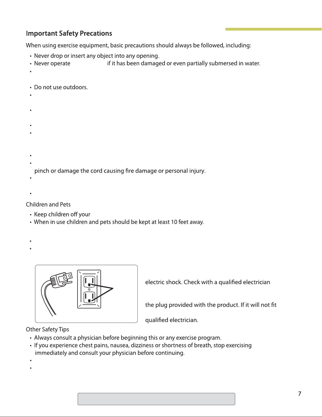
This product is for use on a nominal 120 volt (non GFI) circuit, and has a grounding plug similar to
the illustration below. Never remove or otherwise bypass the eletrical ground terminal.
Danger: Improper connection of the equipment
grounding conductor can result in the risk of
Gounded
Treadmill
Plug
Gounded Wall Outlets
Socket
or service person if you are in doubt as to whether
the product is properly grounded. Do not modify
in the outlet, have the proper outlet installed by a
Do not wear clothing or jewelry that might catch on any part of the treadmill.
This treadmill is equipped with a safety key. If the key is removed from the display, the treadmill will
immediately stop. Always clip the cord that is attached to the safety key to a part of your clothing so
the key will be pulled from the display, stopping the treadmill, in case of an emergency.
Note: Read all instructions and save for future use.
TR800 / TR1200i
Folding Treadmill
treadmill
5
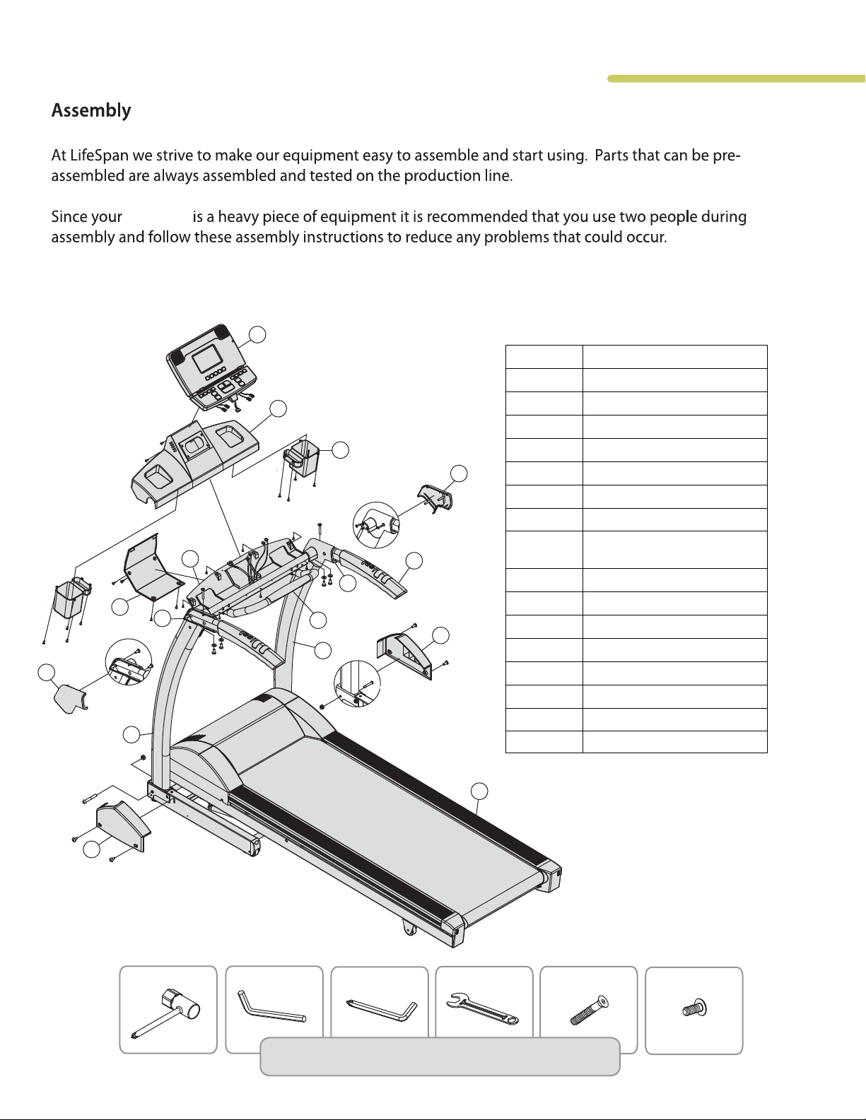
Item# description
1 Main Frame
25
2
3
6
10
4
5 Console
6 Accessory Tray
7 Back cover
8
8
12
7
11
9
15
3
4
9 Left handrail cover-outer
10 Right handrail cover-outer
14
11 Left handrail cover-inner
12 Right handrail cover-inner
13 Base cover-Left
14 Base cover-Right
15 Safety bar cover
2
25
Left handlebar support
Right handlebar support
Handlebar
Plate console housing
frame mount
Console housing
13
Wrench-13mm
Wrench-6mm
Tools and Screws included in Hardware Bag
Wrench-5mm
1
Wrench-17mm
M8*70L (2pcs)
M4*10L (4pcs)
9

Step 1: Unpacking Treadmill
Cut packaging straps and remove.
A.
Remove the box top.
B.
Remove small parts and packaging material and unwrap parts.
C.
Cut corners of the bottom box and remove all packaging material to begin assembly. The
D.
treadmill can be assembled in the box. No need to pick the treadmill up to remove it from box.
Step 2: Handlebar Support Post Assembly
A. Remove the screw (A) and nut (E) that are pre-assembled on the frame from each side of the
base using the 6 mm Allen wrench and 17 mm open end wrench provided in your tool kit.
These two screws will prevent the handlebars from rotating up into their upright position.
B. Stand the support posts and handlebars up into their operating position and re-attach the
screws (A) and nuts (E) removed in step 2A. Tighten securely.
E
A
G
13
C. Attach the left (13) and right (14) base covers using a Phillips screwdriver and 2 machine screws (G)
on each side. The 4 base cover attaching screws are located in the hardware bag.
10
TR800 / TR1200i
Folding Treadmill
Step 3: Handlebar Assembly
A. Rotate the handlebars down so they are positioned on top of the handlebar posts.
Secure the right and left handlebars to the support post using the 2 M8 x70L screws (B)
provided in the hardware bag
B. Rotate the console bracket (8) up in the back until it reaches its normal operating position.
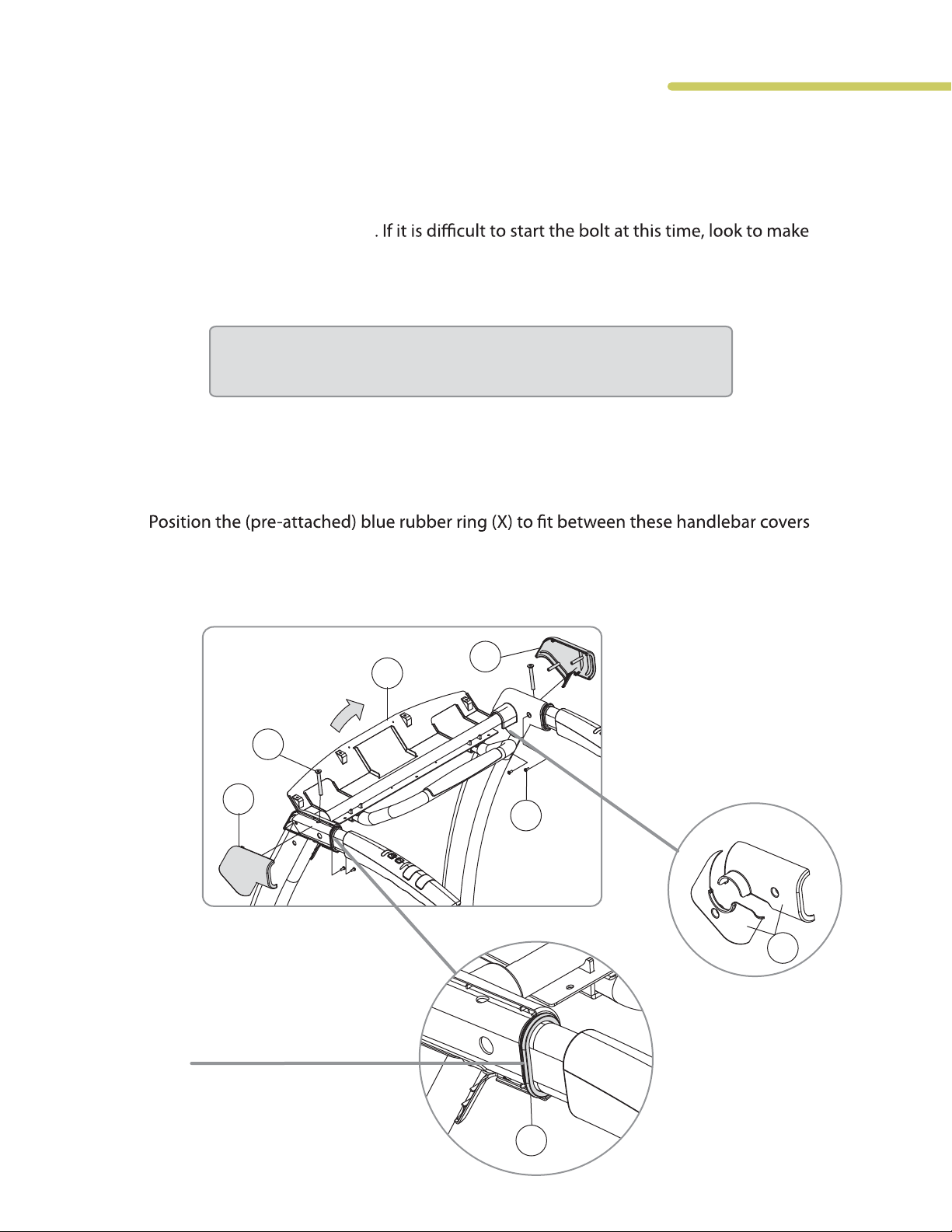
C. Place the left outside handlebar cover (9) next to the inside handlebar cover (pre-attached).
sure there are no wires obstructing the bolt hole. Also, lightly pulling the handlebar
one way or the other will help line up the bolt holes.
Note: Make sure that the wires on both sides are not pinched
in-between the handlebars and the handlebar post.
allowing the plastic ridge to sit in the groove of the blue rubber ring. Secure these three
parts together using the self-tapping screws (C), which are pre-installed in the outer cover.
Repeat this process on the other side with the right outside handlebar cover (10).
10
8
B
9
C
*Note: the TR800 inside handlebar
cover is not pre-attached and
comes in two pieces.
TR800
12
blue rubber ring
X
11

Step 4: Assemble Console Components
A. Attach the blue accessory trays (6) to the
bottom of the console housing using 8
self tapping sc
console housing (25).
B. Attach the console (5) to the console
housing (25) using 6 screws (G). These
screws are pre-installed on the back of the
rews (G). Preinstalled in
25
5
and then reinstalled with the console in
place.
Step 5: Attach Console Assembly
A. Place the console assembly onto the
console housing frame mount (8) and
attach the assembly using the 7
screws (F), preinstalled in console
housing (25). Be sure not to pinch wire
harnesses during this step.
B. Connect all wire harnesses including:
i. Main Harness: 5-pin and 7-pin
Note: TR800 only has 5-pin
ii. Hand Pulse harness: 2-pin
(color doesn’t matter.)
iii. Speed Control Harness: 3-pin
(the wire colors need to be
matched.)
iv. Incline Control Harness: 3-pin
(the wire colors need to be
matched)
C. Tuck extra wiring harness into the
opening behind the console.
G
6
G
F
8
Note: Be careful to properly connect all wiring
connectors with their correct corresponding
wiring harness. Pay attention not to bend any
pins and make sure the connectors click in
place.
12
 Loading...