

Page 1
G3 GYM SYSTEM
ASSEMBLY INSTRUCTIONS
G3-001 / CLASS H / 09/19/08 / 8600401 / REV B-2
Page 2

TABLE OF CONTENTS
Safety Statement . . . . . . . . . . . . . . . . . . . . . . . . . . . . . . . . . . . . . . . . . . . . . . . . . . . . . . . . . . .1
General Notes . . . . . . . . . . . . . . . . . . . . . . . . . . . . . . . . . . . . . . . . . . . . . . . . . . . . . . . . . . . . .3
Tools Required . . . . . . . . . . . . . . . . . . . . . . . . . . . . . . . . . . . . . . . . . . . . . . . . . . . . . . . . . . . . .3
Gym Layout . . . . . . . . . . . . . . . . . . . . . . . . . . . . . . . . . . . . . . . . . . . . . . . . . . . . . . . . . . . . . . .4
Parts List . . . . . . . . . . . . . . . . . . . . . . . . . . . . . . . . . . . . . . . . . . . . . . . . . . . . . . . . . . . . . . . . .5
Cabling Diagrams . . . . . . . . . . . . . . . . . . . . . . . . . . . . . . . . . . . . . . . . . . . . . . . . . . . . . . . . . . .6
Assembly Instructions . . . . . . . . . . . . . . . . . . . . . . . . . . . . . . . . . . . . . . . . . . . . . . . . . . . . . . .11
Maintenance . . . . . . . . . . . . . . . . . . . . . . . . . . . . . . . . . . . . . . . . . . . . . . . . . . . . . . . . . . . . . .31
Warranty . . . . . . . . . . . . . . . . . . . . . . . . . . . . . . . . . . . . . . . . . . . . . . . . . . . . . . . . . . . . . . . .32
Contact Information . . . . . . . . . . . . . . . . . . . . . . . . . . . . . . . . . . . . . . . . . . . . . . . . . . . . . . . . .33
IMPORTANT SAFETY INFORMATION
It is the sole responsibility of the purchaser of LIFE FITNESS products to read the owner's manual, warning labels and
instruct all individuals, whether they are the end user or supervising personnel on proper usage of the equipment.
UNDERSTANDING EACH AND EVERY WARNING TO THE FULLEST IS IMPORTANT. IF ANY OF THESE INSTRUCTIONS OR WARNINGS ARE UNCLEAR, CONTACT LIFE FITNESS CUSTOMER SERVICE IMMEDIATELYAT 1-800-
351-3737 WITHIN THE US AND CANADA. INTERNATIONAL OFFICE CONTACT INFORMATION IS AVAILABLE ON
PAGE 33.
Keep children away from strength equipment. Parent or others supervising children must provide close supervision of
children if the equipment is used in the presence of children.
This equipment is categorized as class H per EN 957-1. And as such this equipment is only intended for Home use. It is
not intended for commercial, institutional and/or studio facilities use. Contact LIFE FITNESS with any questions regarding this classification.
It is recommended that all users of LIFE FITNESS exercise equipment be informed of the following information prior to
use.
ACCESS CONTROL
LIFE FITNESS recommends that all fitness equipment be used in a supervised area. It is recommended that the
equipment be located in an access controlled area. Control is the responsibility of the facility owner.
INSTALLATION
SECURING EQUIPMENT - LIFE FITNESS recommends that all equipment be secured to a solid, level surface
to stabilize and eliminate rocking or tipping over. This must be performed by a licensed contractor.
PROPER USAGE
1 Do not use any equipment in any way other than as designed or intended by the manufacturer. It is impera-
tive that LIFE FITNESS equipment is used properly to avoid injury.
2. Injuries may result if exercising improperly or excessively. It is recommended that all individuals consult a
physician prior to commencing an exercise program. If at any time during exercise you feel faint, dizzy or
experience pain, STOP EXERCISING and consult your physician.
3. Keep body parts (hands, feet, hair, etc.), clothing and jewelry away from moving parts to avoid injury.
4. When adjusting any seat, knee hold down pad, range of motion limiter, foothold pad, pulley or any other type
of adjuster, make certain that the adjusting pin is fully engaged in the hole to avoid injury.
1
Page 3

INSPECTION
1 DO NOT use or permit use of any equipment that is damaged and or has worn or broken parts. For all LIFE
FITNESS equipment use only replacement parts supplied by LIFE FITNESS.
2. Cables and Belts pose an extreme liability if used when frayed. Always replace any cable at first sign of
wear (consult LIFE FITNESS if uncertain).
3. Routinely inspect all accessory clips that join attachments to the cables and replace at the first sign of wear.
4. MAINTAIN LABELS AND NAMEPLATES - Do not remove labels for any reason. They contain important
information. If unreadable or missing, contact LIFE FITNESS for a replacement.
5. EQUIPMENT MAINTENANCE - Preventative maintenance is the key to smooth operating equipment as well
as keeping your liability to a minimum. Equipment needs to be inspected at regular intervals.
6. Ensure that any person(s) making adjustments or performing maintenance or repair of any kind is qualified
to do so. LIFE FITNESS will provide service and maintenance training at our corporate facility upon request
or in the field if proper arrangements are made.
7. Before any use, examine all accessories approved for use with the LIFE FITNESS equipment for damage or
wear, including, but not limited to, examining the Hammer Strength Training Vest for damage or wear on the
rings or the webbing or stitching holding the rings in place.
8. DO NOT ATTEMPT TO USE OR REPAIR ANY ACCESSORY APPROVED FOR USE WITH THE LIFE FITNESS EQUIPMENT WHICH APPEARS TO BE DAMAGED OR WORN.
OPERATING WARNINGS
1. It is the purchaser's sole responsibility to properly instruct its end users and supervising personnel as to the
proper operating procedures of all LIFE FITNESS equipment.
2. Keep children away from strength equipment. Parent or others supervising children must provide close
supervision of children if the equipment is used in the presence of children.
3. Do not allow users to wear loose fitting clothing or jewelry while using equipment. It is also recommended to
have user's secure long hair back and up to avoid contact with moving parts.
4. All bystanders must stay clear of all users, moving parts and attached accessories and components while
machine is in operation.
SELECTORIZED WEIGHT STACK SYSTEMS
1. Use only weight selector pins supplied by LIFE FITNESS on weight stacks. Substitutes are forbidden.
2. Fully insert weight selector pins. Partial insertion can cause weights to fall unexpectedly.
3. Never pin the weight stack in an elevated position.
4. Never remove selector pin if any weights are suspended.
5. Never attempt to release jammed weights or parts.
6. Never use dumbbells or other means to incrementally increase the weight resistance. Use only those means
provided by LIFE FITNESS.
Note: In our continuing effort to improve our products, specifications are subject to change.
©2008 Life Fitness, a division of Brunswick Corporation. All rights reserved.
www.lifefitness.com
2
Page 4
IMPORTANT NOTES
Thank you for purchasing the Life Fitness G3 Gym System. Please read these instructions thoroughly and keep them for future reference.
This product must be assembled on a flat, level surface to assure its proper function.
DO NOT securely tighten any frame connections until the entire frame has been assembled, unless
otherwise stated.
TOOLS
REQUIRED FOR ASSEMBLY
O
Rubber mallet or hammer.
O
3/4" wrench.
O
9/16" wrench.
O
Ratchet with 3/4" and 9/16" sockets.
O
5/32" Allen wrench.
O
3/16" Allen wrench
O
Adjustable wrench.
O
Tape measure.
BOLT LENGTH RULER
NOTE THAT BOLT LENGTH IS MEASURED FROM THE UNDERSIDE OF THE HEAD OF THE BOLT.
3
BOLT LENGTH
1/2 1/2 1/2 1/2 1/2 1/2
0
1
2
345
6
Page 5
4
G3 FOOTPRINT
1 SQUARE = 1' X 1'
M
AXIMUM USER WEIGHT:
300 lbs (136 kg)
MINIMUM
REQUIRED USABLE SPACE:
Length = 90 inches (229 cm) 7' 6"
Width = 103 inches (262 cm) 8' 7"
Height = 84 inches (213.5 cm) 7'
Weight = 392 lbs (178 kg)
D
IMENSIONS INCLUDING LEG PRESS (OPTIONAL):
Length = 102 inches (259 cm) 8' 6"
Width = 130 inches (330 cm) 10' 10"
1’
2’
3’
4’
5’
6’
4’
5’ 6’ 7’
8’
9’1’ 2’ 3’
7’
8’
9’
Page 6

5
PARTS LIST
NOTE: Some of the components may be pre-assembled.
1 FRONT BASE 1
2 UPRIGHT 1
3 BASE CONNECTOR 1
4 REAR BASE 1
5 RIGHT ARM 1
6 LEFT ARM 1
7 SEATADJUST 1
8 LEG PEDESTAL 1
9 BACK PAD 1
10 PULLEY PLATE 2
11 BASE PLATE 2
12 C-RING 2
13 BOOM PULLEY PLATE 2
14 RIGHT BOOM PLATE 1
15 LEFT BOOM PLATE 1
16 SEAT PAD 1
17 ROLLER PAD 6
18 76" GUIDE ROD 2
19 ADJUST. SEWN HANDLE 2
20 SHORT SEWN HANDLE 2
21 WEIGHT PLATE 15
22 LOW ROW BAR 1
23 HEAD PLATE ASSY 1
24 3/4 X 18" TUBE 1
25 3/4 X 18-3/8" TUBE 1
26 3/4 X 21" TUBE 1
27 WEIGHT STACK PIN 1
28 WEIGHT STACK CUSHION 2
29 102 3/4” WEIGHT STACK CABLE 1
30 163 1/8” LEG CABLE 1
31 215 1/16” ARM CABLE 1
32 181” BOOM CABLE 1
33 WEIGHT STACK SPACER 2
34 3-1/2" CABLE GUARD 1
35 4-1/2" CABLE GUARD 1
36 SHAFT COLLAR 2
37 3-1/2" PULLEY 18
38 4-1/2" PULLEY 3
39 QUICK CONNECT 4
40 T-HANDLE SPRING PIN 1
41 SNAP LINK 4
42 GUIDE BRACKET 2
43 5-PRONG KNOB 1
44 ROLLER PAD CAP 6
45 PLASTIC WASHER 12
46 1/2" RH WASHER 2
47 RH CAP 2
48 3/8 X 3/4" FLANGE SPACER 2
49 3/8 X 1-1/16" FLANGE SPACER 2
50 ACCESSORY RING 4
51 3/8" X 1" SPACER 9
52 WEIGHT STACK LABEL 1
53 3/8 X 1-3/4" BOLT 10
54 5/16 x 1" BUTTON HEAD 6
55 3/8 X 2" BOLT 2
57 3/8 X 3-3/4" BOLT 17
58 1/2 X 104mm BOLT 1
59 12 LINK CHAIN 1
60 3/8 X 2-3/4" BOLT 2
61 1/2 X 5-3/4" BOLT 1
62 1/2" LOW HEIGHT LOCK NUT 2
63 3/8" SILVER LOCK NUT 35
64 3/8" FLAT WASHER 24
65 61” FRONT GUIDE CABLE 2
66 FOOT PLATE 1
67 3/8 X 3" SILVER BOLT 2
68 3/8 X 4-1/4" SILVER BOLT 6
70 3/8 X 1-1/4" BOLT 2
71 BACK PAD ADJUSTMENT 1
72 SWIVEL PULLEY ASSEMBLY 2
73 ANKLE STRAP 1
74 71.5” REAR GUIDE CABLE 2
75 ACCESSORY ADAPTER BAR 1
76 ACCESSORY LAT BAR 1
77 3/8 X 3" BLACK BOLT 2
78 3/8” BLACK LOCK NUT 2
79 EXERCISE CARD 1
80 TOUCH-UP PAINT (Platinum) 1
81 TOUCH-UP PAINT (Shadow Gray) 1
82 SILICON 1
Key Description Qty Key Description Qty
Page 7
6
CABLE END ASSEMBLY:
Slide parts onto cable in the following order: Item 2, Item 4, Item 3.
Insert cable end into Item 1.
Slide entire assembly over Item 1 and secure it by screwing one Item 5 through Item 2 and into both
sides of Item 1 and tightening.
Note: The following five Cabling Diagrams will be referenced in the assembly instruction steps.
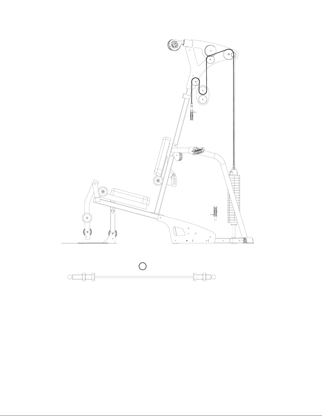
CABLING DIAGRAM 1
ITEM QTY. PART NO. DESCRIPTION
1 1 7726201 COUPLER, QUICK CONNECT
2 1 7726401 HSNG, QUICK CONNECT
3 1 7726301 SLEEVE, QUICK CONNECT
4 1 3249901 SPRING, QUICK CONNECT
5 2 3250002 M5 X 0.8 HXS SOC CS ST BZ X 8
Page 8
7
CABLING DIAGRAM 2
29
Page 9
8
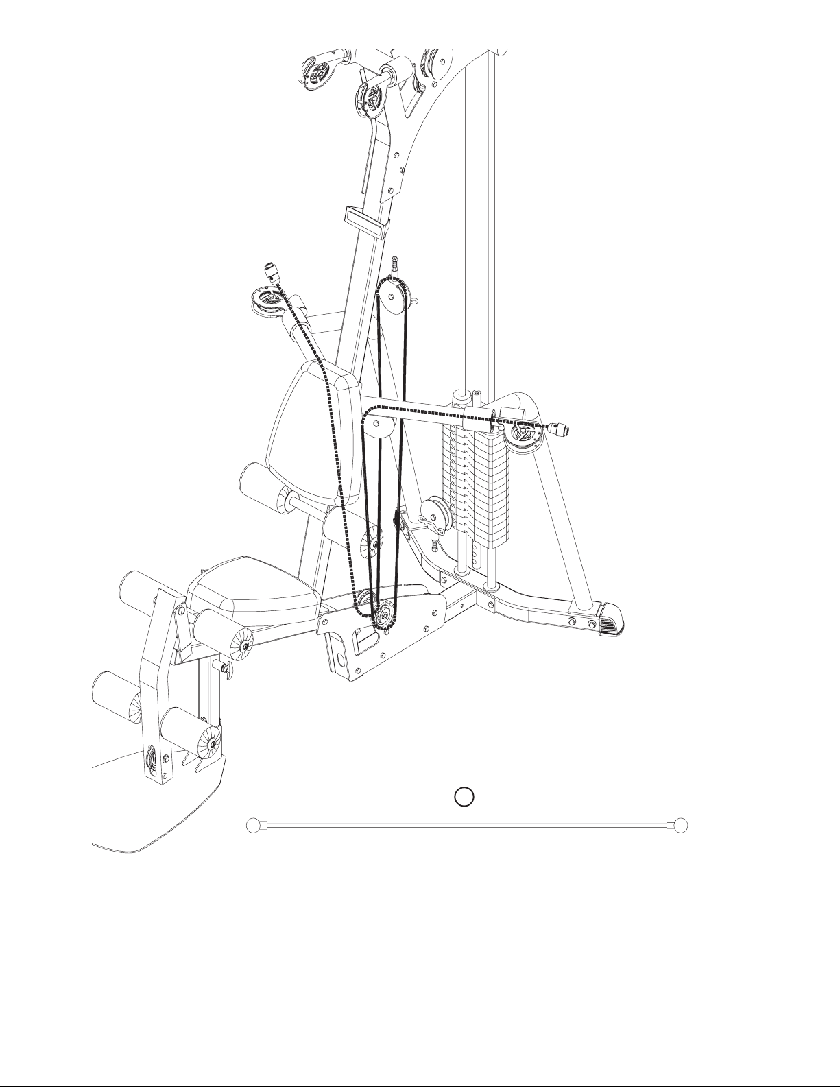
CABLING DIAGRAM 3
32
Page 10
9
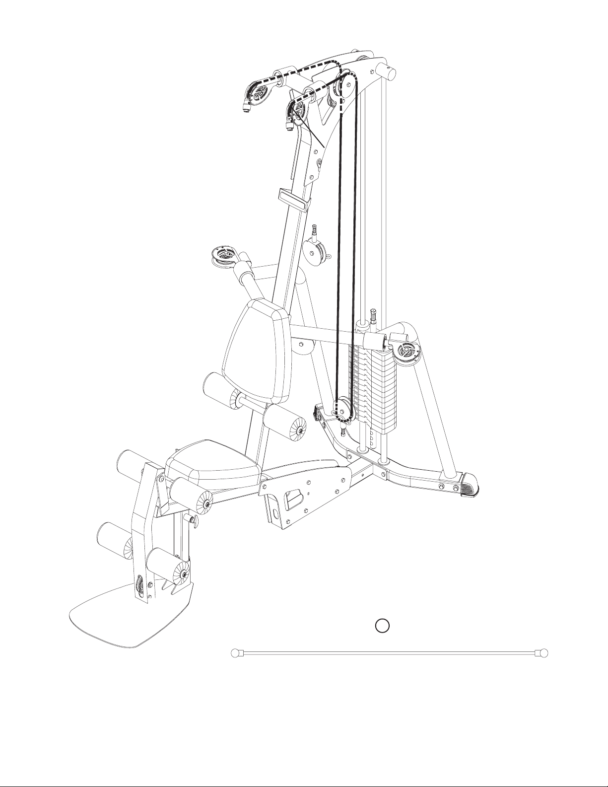
CABLING DIAGRAM 4
31
Page 11
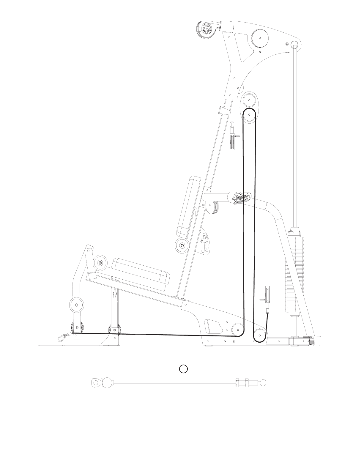
10
CABLING DIAGRAM 5
30
Page 12

11
STEP 1:
• Loosely assemble two BASE PLATES (11) to the FRONT BASE (1) and the BASE CONNECTOR
(3) using four 3/8 x 3-3/4" BOLTS (57) and four 3/8" SILVER LOCK NUTS (63). See Figure 1.
• Loosely assemble the FOOTPLATE (66) to the FRONT BASE (1) using one 3/8 x 3" BLACK
BOLT (77) and one 3/8" BLACK LOCK NUT (78) as shown in Figure 1.
• Loosely assemble the REAR BASE (4) to the BASE CONNECTOR (3) using two 3/8 x 3-3/4"
BOLTS (57), two 3/8" WASHERS (64) and two 3/8" SILVER LOCK NUTS (63).
• Loosely assemble the UPRIGHT (2) to the FRONT BASE (1) using two 3/8 x 2-3/4" BOLTS (60),
two 3/8" WASHERS (64) and two 3/8" SILVER LOCK NUTS (63).
FIGURE 1
2
3/8 X 2-3/4”
63
1
7
3
8
6
6
60
63
64
64
63
7
7
3
57
57 3/8 X 3-3/4”
11
3/8 X 3”
4
Page 13

12
STEP 2:
• Loosely assemble the RIGHT ARM (5) and REAR BASE (4) using two 3/8 x 3-3/4" BOLTS (57),
two 3/8" WASHERS (64) and two 3/8" SILVER LOCK NUTS (63).
• Loosely assemble the LEFT ARM (6) and REAR BASE (4) using two 3/8 x 3-3/4" BOLTS (57), two
3/8" WASHERS (64) and two 3/8" SILVER LOCK NUTS (63).
• Loosely assemble both the LEFT ARM (6) and the RIGHT ARM (5) to the UPRIGHT (2) using two
3/8 x 4-1/4" SILVER BOLTS (68), four 3/8" WASHERS (64) and two 3/8" SILVER LOCK NUTS
(63).
63
FIGURE 2
5
6
64
2
68
3/8 X 4-1/4”
63
4
64
57
3/8 X 3-3/4”
1/2 1/2 1/2 1/2 1/2 1/2
0
1
2
345
6
Page 14

13
21
FIGURE 4
FIGURE 3
Make sure that the WEIGHT PLATES (21) are assembled as shown in Figure 3 and the HEAD
PLATE ASSEMBLY (23) is assembled as shown in Figure 4.
23
Page 15

14
STEP 5:
• Place the GUIDE RODS (18) through the BOTTOM SHROUD BRACKET and into the REAR
BASE (4) as shown in Figure 5.
• Lubricate the GUIDE RODS (18) with the included silicon package.
• Slide two WEIGHT STACK SPACERS (33) and two WEIGHT STACK CUSHIONS (28) over the
GUIDE RODS (18). Note: WEIGHT STACK SPACERS are not required with add-on weight stack
option.
• Using extreme care, slide all fifteen WEIGHT PLATES (21) over the GUIDE RODS (18) and down
onto the WEIGHT STACK CUSHIONS (28). Make sure the WEIGHT PLATES (21) all face as
shown.
• Slide the HEAD PLATE ASSEMBLY (23) down the GUIDE RODS (18), onto the weight plate
stack.
• Slide two SHAFT COLLARS (36) over the GUIDE RODS (18) as shown in Figure 5.
28
F
IGURE 5
36
18
23
21
33
Bottom Shroud Bracket
4
Page 16

15
STEP 6:
A. Swing the GUIDE RODS (18) into the guide rod bushings in the RIGHT BOOM PLATE (14) and
LEFT BOOM PLATE (15) as shown in Figure 6.
B. Loosely assemble the RIGHT BOOM PLATE (14) and LEFT BOOM PLATE (15) to the UPRIGHT
(2) using three 3/8 x 3-3/4" BOLTS (57) and three 3/8" SILVER LOCK NUTS (63). See Figure 6.
D. Slide the SHAFT COLLARS (36) to the top of the GUIDE RODS (18) and tighten the set screws
as shown in Figure 6.
STEP 7:
A. Securely assemble one SEAT PAD (16) to the SEATADJUST (7) using two 3/8 x 3" SILVER
BOLTS (67) and two 3/8" WASHERS (64). See Figure 7.
14
FIGURE 6
F
IGURE 7
15
57
18
36
3/8 X 3-3/4”
63
2
16
7
64
3/8 X 3”
67
Page 17

16
STEP
8:
• Securely assemble the FIVE PRONG KNOB (43) to the FRONT BASE (1) as shown.
• Insert the SEAT ADJUST (7) into the FRONT BASE (1) as shown. The seat height can be adjusted using the Spring Pin and can be secured with the FIVE PRONG KNOB (43).
• Assemble the LEG PEDESTAL (8) to the FRONT BASE (1) using two RH CAPS (47), one 1/2 x
104mm BOLT (58), two 1/2" WASHERS (46) and one 1/2" LOW HEIGHT LOCK NUT (62).
NOTE: Tighten this connection enough to prevent excess play; yet allow the Leg Pedestal to
rotate freely.
1/2 X 104mm
FIGURE 8
43
58
7
46
8
1
62
47
SPRING PIN
Page 18

17
STEP
9:
• Detach the Short Cable from both REAR GUIDE CABLES (74) as shown in Figure 9 (B).
• Slide the Long Cables of the REAR GUIDE CABLES (74) through the eyelets of the GUIDE
BRACKET (42) as shown in Figure 9 (B). Reattach the Short Cable of the REAR GUIDE CABLES
(74) to the Long Cable, leaving the GUIDE BRACKET (42) loose.
• Assemble two BOOM PULLEY PLATES (13) and two 3-1/2" PULLEYS (37) to the RIGHT and
LEFT BOOM PLATES (14 & 15) using two 3/8 x 1-3/4" BOLTS (53) and two 3/8" SILVER LOCK
NUTS (63). See Figure 9.
• Loosely assemble one 4-1/2" PULLEY (38), one 4-1/2" CABLE GUARD (35) and one 1" SPACER
(51) to the RIGHT and LEFT BOOM PLATES (14 &1 5), using one 3/8 x 3-3/4" BOLT (57), one
SILVER 3/8" LOCK NUT (63), and two 3/8” WASHERS (64).
• Loosely assemble one 3-1/2" PULLEY (37), one 3-1/2" CABLE GUARD (34), one 1" SPACER
(51) and both REAR GUIDE CABLES (74) to the RIGHT and LEFT BOOM PLATES (14 & 15),
using one 3/8 x 4-1/4" SILVER BOLT (68), one 3/8” SILVER LOCK NUT (63), and two 3/8” WASHERS (64).
NOTE: The GUIDE BRACKET (42) will remain loose until attached to the pulley assembly in a
later step. Securely tighten all the nuts and bolts on the gym, starting with the nuts and bolts on
the frame, before proceeding any further.
FIGURE 9
Page 19

18
IMPORTANT!
U
NCOIL AND STRAIGHTEN ALL CABLES TO REMOVE ALL TWISTS BEFORE
INSTALLING.
STEP 10:
• Assemble the WEIGHT STACK PIN (27) to
the HEAD PLATE ASSEMBLY (23) as shown
in Figure 10.
• Screw the long threaded end of the WEIGHT
STACK CABLE (29) into the end of the
HEAD PLATE ASSEMBLY (23). See Figure
10.
• Route the WEIGHT STACK CABLE (29)
around the pulleys in the RIGHT and LEFT
BOOM PLATES (14 & 15) as shown in
Figure 10.
NOTE: Make sure the cable runs in the
grooves of the pulleys.
• Tighten the two 3/8 x 3-3/4" Bolts (57) holding the 3-1/2" CABLE GUARD (34) and the
4-1/2" CABLE GUARD (35).
NOTE: Make sure the guards are oriented
correctly.
• Assemble the two PULLEY PLATES (10)
around one 3-1/2" PULLEY (37), using one
3/8 x 1-3/4" BOLT (53) and one 3/8" SILVER
LOCK NUT (63) as shown in Figure 10.
F
IGURE 10
63
14
15
29
37
27
10
23
3/8X 1-3/4”
53
Page 20

19
STEP 11:
• Loop the WEIGHT STACK CABLE (29) around one 3-1/2" PULLEY (37).
• Assemble the 3-1/2" PULLEY (37) with the WEIGHT STACK CABLE (29) around it to the RIGHT
and LEFT BOOM PLATES (14 & 15) using one 3/8 x 4-1/4" SILVER BOLT (68), two 3/8" FLAT
WASHERS (64), two GUIDE CABLES (65), two 3/8 x 1" SPACERS (51) and one 3/8" SILVER
LOCK NUT (63). See Figure 11.
• Screw the short threaded end of the WEIGHT STACK CABLE (29) into the end of the GUIDE
BRACKET (42). See Figure 11.
• Disassemble the Short Cables and the Turnbuckles on the ends of the GUIDE CABLES (65) as
shown in Figure 11. Set these pieces aside. The Guide Cables will be reassembled later.
37
FIGURE 11
51
63
29
64
2
42
3/8 X 4-1/4"
68
65
TURN BUCKLE
SHORT CABLE
Page 21

20
STEP 12:
• Loop the BOOM CABLE (32) around one 3-1/2" PULLEY (37).
• Assemble the 3-1/2" PULLEY (37) with the BOOM CABLE (32) looped around it to the GUIDE
BRACKET (42), using one 3/8 x 1-3/4" BOLT (53) and one 3/8" SILVER LOCK NUT (63).
• Attach the Quick Connect system to the cable end using the instructions on page 6.
FIGURE 12
Page 22

21
S
TEP 13:
• Securely assemble the ball end of the LEG CABLE (30) and one 3-1/2" PULLEY (37) to the LEG
PEDESTAL (8), using one 3/8 x 3-3/4" BOLT (57), two 3/8 x 1-1/16" FLANGE SPACERS (49),
and one 3/8" SILVER LOCK NUT (63).
• Securely assemble one 3-1/2" PULLEY (37) to the FRONT BASE (1), using one 3/8 x 3" CLEAR
ZINC BOLT (67), two 3/8 x 3/4" FLANGE SPACERS (48) and one 3/8" BLACK LOCK NUT (78).
NOTE: The LEG CABLE (30) must be routed over the retaining bolt as shown in Figure 13.
• Carefully slide the GUIDE CABLES (65) through the GUIDE BRACKET (42) as shown in Figure
13 (B).
• Reassemble the ends of the GUIDE CABLES (65) as shown in Figure 13 (B) by attaching the
Short Cables and Turnbuckles that were removed in Step 11 (D).
• Assemble one 3-1/2" PULLEY (37) to the BASE PLATES (11), using one 3/8 x 4-1/4" SILVER
BOLT (68), two 3/8" FLAT WASHERS (64), two GUIDE CABLES (65), two 3/8 x 1" SPACERS (51)
and one 3/8" SILVER LOCK NUT (63).
NOTE: Loop the LEG CABLE (30) around the 3-1/2" PULLEY (37) before attaching it to the BASE
PLATES (11), as shown in Figure 13.
• Adjust the Turnbuckle on each GUIDE CABLE (65) to add tension to the GUIDE CABLES (65)
until they are taut. Secure Turnbuckle with the Jam Nuts as seen in Figure 13 (B).
78
FIGURE 13
63
51
64
8
3/8 X 4-1/4” 68
2
11
30
3/8 X 3”
(B)
42
TURN BUCKLE
SHORT CABLE
65
48
37
49
77
3/8 X 3-3/4” 57
Page 23

22
F
IGURE 14
S
TEP 14:
• Securely assemble one 3-1/2"
PULLEY (37) to the PULLEY
PLATES (10), using one 3/8 x 1-3/4"
BOLT (53) and one 3/8" SILVER
LOCK NUT (63).
NOTE: Loop the LEG CABLE (30)
over the PULLEY (37) before assembling the PULLEY PLATES (10) as
shown in Figure 14.
S
TEP 15:
• Securely assemble one 3-1/2"
PULLEY (37) and both REAR GUIDE
CABLES (74) to the BASE PLATES
(11), using one 3/8 x 4-1/4" SILVER
BOLT (68), two 3/8 x 1" SPACERS
(51) and one SILVER 3/8" LOCK
NUT (63).
NOTE: Loop the LEG CABLE (30)
under the PULLEY (37) before
assembling the BASE PLATES (11),
as shown in Figure 15.
• Adjust the Turnbuckle at the top of
each REAR GUIDE CABLE (74) to
add tension to the REAR GUIDE
CABLES (74) until they are taut.
• Screw the threaded end of the LEG
CABLE (30) into the end of the
PULLEY BRACKET (42).
FIGURE 15
Page 24

23
STEP 16:
• Route the ARM CABLE (31) through the LEFT ARM (6) as shown in Figure 16.
• Loop the ARM CABLE (31) around one 4-1/2" PULLEY (38).
• Securely assemble the 4-1/2" PULLEY (38) with the ARM CABLE (31) around it to the LEFT ARM
(6), using one 3/8 x 2" BOLT (55) and one 3/8" SILVER LOCK NUT (63).
FIGURE 16
Page 25

24
STEP 17:
• Securely assemble two 3-1/2" PULLEYS (37) to the BASE PLATES (11), using two 3/8 x 3-3/4"
BOLTS (57), one 3/8 x 1" SPACER (51) and two 3/8" SILVER LOCK NUTS (63).
• Loop the ARM CABLE (31) between the two PULLEYS (37) around one 3-1/2" PULLEY (37) as
shown in Figure 17.
• Securely assemble the 3-1/2" PULLEY (37) with the Arm Cable (31) around it to the GUIDE
BRACKET (42), using one 3/8 x 1-3/4" BOLT (53) and one 3/8" SILVER LOCK NUT (63).
F
IGURE 17
Page 26

25
STEP 18:
• Route the ARM CABLE (31) through the RIGHT ARM (5) as shown in Figure 18.
• Loop the ARM CABLE (31) around one 4-1/2" PULLEY (38).
• Securely assemble the 4-1/2" PULLEY (38) with the ARM CABLE (31) around it to the RIGHT
ARM (5), using one 3/8 x 2" BOLT (55) and one 3/8" SILVER LOCK NUT (63).
FIGURE 18
Page 27

26
STEP 19:
• Insert the ARM CABLE (31) ends through the SWIVEL PULLEY ASSEMBLIES (72).
• Insert the SWIVEL PULLEY ASSEMBLIES (72) into the LEFT ARM (6) and the RIGHT ARM (5).
• Secure the SWIVEL PULLEY ASSEMBLIES (72) in the LEFT ARM (6) and the RIGHT ARM (5)
using one C-RING (12) each.
• Attach the QUICK CONNECT SYSTEM (39) to each end of the ARM CABLE (31). See Diagram
1, page 6.
FIGURE 19
Page 28

27
STEP 21:
• Assemble two ROLLER PADS (17) to the LEG PEDESTAL (8) using one 3/4 x 18" TUBE (24),
four PLASTIC WASHERS (45), two ROLLER PAD CAPS (44) and two 5/16 x 1" BUTTON HEAD
ALLEN SCREWS (54).
• Assemble two ROLLER PADS (17) to the SEAT ADJUST (7) using one 3/4 x 18-3/8" TUBE (25),
four PLASTIC WASHERS (45), two ROLLER PAD CAPS (44) and two 5/16 x 1" BUTTON HEAD
ALLEN SCREWS (54).
• Assemble two ROLLER PADS (17) to the BACK PAD ADJUSTMENT (71) using one 3/4 x 21"
TUBE (26), four PLASTIC WASHERS (45), two ROLLER PAD CAPS (44) and two 5/16 x 1" BUTTON
HEAD ALLEN SCREWS (54).
STEP
20:
• Securely assemble one BACK PAD (9) to the BACK PAD ADJUSTMENT (71) using two 3/8 x 11/4" BOLTS (70) and two 3/8" WASHERS (64).
• Securely assemble the BACK PAD ADJUSTMENT (71) to the UPRIGHT (2), using one 1/2 x 53/4" BOLT (61) and one 1/2" LOW HEIGHT LOCK NUT (62).
FIGURE 20
FIGURE 21
9
62
71
3/8 X 1-1/4”
64
70
2
61
1/2 X 5-3/4”
Page 29

28
S
TEP 22:
• Make adjustments to the cables’ tension at the locations shown in Figure 22.
• Adjust the Turnbuckle on each GUARD CABLE (65) to change the tension of the GUIDE CABLES
(65).
• If by the time the Gym is assembled, the HEAD PLATE (23) does not sit on top of the first
WEIGHT PLATE (21), push the HEAD PLATE (23) down, insert the WEIGHT STACK PIN (27)
and perform several repetitions. This will relax the cable system and prevent the HEAD PLATE
(23) from lifting up.
• If after completing the previous step, the HEAD PLATE (23) still does not sit on top of the first
WEIGHT PLATE (21) or if there is excess slack in the cable system, adjust the threaded ends of
the Cables attached to the PULLEY BRACKETS (42) accordingly and retighten the jam nuts.
• For maximum performance, the HEAD PLATE (23) should just barely sit on the Weight Plate (21).
• After making adjustments, make sure all jam nuts are securely tightened.
FIGURE 22
75
59
76
20
42
ADJUSTMENT
CABLE USING
23
JAM NUT
19
50
ADJUSTMENT
9
65
C
J
73
A
A
BLE
M
U
N
S
G
I
U
N
T
TURN BUCKLE
ADJUSTMENT
41
22
Page 30

29
STEP 23:
• SECURELY assemble the TOP SHROUD BRACKET (3) to the RIGHT and LEFT BOOM PLATES
using two 3/8 X 2-1/2” BOLTS (7) and two 3/8” SILVER LOCK NUTS (8) as shown in FIGURE 23.
The BOTTOM SHROUD BRACKET (4) was previously inserted under the weight stack.
PA R T S L I S T
DESCRIPTION
KEY
LEFT SHROUD
1
2
RIGHT SHROUD
3
TOP SHROUD BRACKET
4
BOTTOM SHROUD BRACKET
FIGURE 23
QTY
1
1
1
1
KEY
5
6
7
8
RIGHT BOOM PLATE
DESCRIPTION
3/8 X 1” BUTTON HEAD BOLT
3/8” BLACK SAE WASHER
3/8 X 2-1/2” BOLT
3/8” LOCK NUT
7 3/8 X 2-1/2”
8
QTY
8
8
2
2
LEFT BOOM PLATE
3
4
Page 31

30
This completes the assembly of the G3 Gym System.
STEP 24:
A. SECURELY assemble the LEFT SHROUD (1) and RIGHT SHROUD (2) to the TOP (3) and
BOTTOM (4) SHROUD BRACKETS using eight 3/8 X 1” BUTTON HEAD BOLTS (5) and eight
3/8” BLACK SAE WASHERS (6) as shown in FIGURE 2.
B. One M4 X 20mm SHOULDER BOLT, M4 WASHER, and M4 NUT are pre-assembled to the
shroud. Use use the M4 X 20MM SHOULDER BOLT to hang the G3 Exercise Cards.
FIGURE 24
2
53/8X1”
BUTTON
HEAD
6
1
Page 32

MAINTENANCE
O
We recommend cleaning your product (pads and frame) on a regular basis, using warm
soapy water. Touch-up paint can be purchased from your Life Fitness customer service representative at 1-800-351-3737.
O
Inspect equipment daily. Tighten all loose connections and replace worn parts immediately.
Failure to do so may result in serious injury.
O
Lubricate guide rods with a teflon based (or equivalent) lubricant on a regular basis.
O
PLEASE RECORD THE INFORMATION REQUESTED BELOW. IN THE EVENT THAT
YOUR EQUIPMENT REQUIRES SERVICE YOU WILL BE ASKED FOR THIS INFORMATION. .
Remember to fill out your registration card on-line at www.lifefitness.com/registration.
MODEL #______________________________________________________
SERIAL #______________________________________________________
DATE OF PURCHASE:___________________________________________
DEALER’S NAME: ______________________________________________
DEALER’S PHONE # ____________________________________________
THANK YOU FOR PURCHASING THE LIFE FITNESS G3 GYM SYSTEM!
31
SERIAL NUMBER LOCATION
Page 33

32
WARRANTY
Life Fitness extends the following LIMITED WARRANTY to the original owner of the Life Fitness products. The Warranty
terms apply to IN HOME USE ONLY.
1. LIMITED WARRANTY ON FRAME AND WELDS. If the frame of the Life Fitness product or a weld should crack or
break, it will be repaired or replaced by Life Fitness. Terms: Lifetime – for so long as the Customer owns the Life
Fitness product.
2. LIMITED WARRANTY ON PARTS. If the following parts are defective in material or workmanship, Life Fitness will
supply replacement parts: all bolts, nuts, washers, bearings, bushings, pulleys, thumbscrews, collars, cable retaining
clips, adjustable pre-stretch slides, roller pad shafts, allen head bolts, weight selector pin, weight stack shaft, set
screws, protector caps, adjustment chain, cotter pin, plunger, spring and knob. Terms: Lifetime – for so long as the
Customer owns the Life Fitness product.
3. LIMITED WARRANTY ON CABLES AND UPHOLSTERY. If the coated cables or upholstery are defective in material
or workmanship, Life Fitness will repair or replace them, at its option. Terms: Three (3) years.
4. CONDITIONS AND EXCEPTIONS. Any product misuse, abuse or alteration, any attempt to repair by a person other
than an authorized Life Fitness Service Center, any improper assembly, accident, or any other condition resulting
from occurrences beyond the control of Life Fitness will void this Limited Warranty.
5. REPLACEMENT AND REPAIR EXPENSES. Life Fitness will provide only replacement parts or repair under this war-
ranty. The Owner is responsible for all other costs. Such costs may include, but are not limited to: a. labor charges
for service, removal, repair or reinstallation of the Life Fitness product or any component part; b. shipping, delivery,
handling and administrative charges for returning parts to Life Fitness; and c. all necessary or incidental costs related to installation of the replacement parts.
6. SHIPPING. If shipping by the Owners is deemed necessary (in sole discretion of Life Fitness), parts should be
shipped in their original carton or equivalent packaging, fully insured with shipping charges prepaid. Life Fitness will
not assume any responsibility for any loss or damage incurred in shipping.
7. CLAIM PROCEDURES. If service on your Life Fitness product is required during the warranty period, please contact
our Customer Service Department at 1-800-351-3737 for instructions regarding returning or replacing parts. Please
have available the following information: (i) the dealer’s name; (ii) the date of purchase; (iii) the serial # (s) of your
product (the serial number location is called out on the final assembly drawing included with your assembly instruction); (iv) a description of the nature of the problem.
8. OWNER’S RIGHT. This Limited Warranty gives you specific legal rights. You may also have other rights, which vary
depending on local law.
9. LIMITATION OF IMPLIED WARRANTIES. All implied warranties, except to the extent prohibited by applicable law,
shall have no greater duration than the warranty period set forth above. There are no warranties which extend
beyond the description in this Limited Warranty.
Because local laws do not allow limitations on how long an implied warranty lasts, the above limitations may not
apply to you.
10. DISCLAIMER. No other express warranty has been made or will be made on behalf of Life Fitness with respect to
any Life Fitness product or the operation, repair or replacement of any Life Fitness product. Life Fitness shall not be
responsible for injury, loss of use of the Life Fitness product, inconvenience, loss or damage to personal property,
whether direct or indirect, and incidental or consequential damages. The above limitation or exclusion may not apply
to you.
Page 34

33
CORPORATE HEADQUARTERS
5100 North River Road
Schiller Park, Illinois 60176 • U.S.A.
847.288.3300 • FAX: 847.288.3703
800.735.3867 (Toll-free within U.S.A., Canada)
INTERNATIONAL OFFICES
AMERICAS
North America
Life Fitness Inc.
5100 N River Road
Schiller Park, IL 60176 U.S.A
Telephone: +1(847) 288 3300
Fax: +1(847) 288 3703
Service Email: internationalservicesupport@lifefitness.com
Sales/Marketing Email: commercialsales@lifefitness.com
Operating Hours: 7:00 am-6:00 pm (CST)
Brazil
Life Fitness Do Brazil
Av. Dr. Dib Sauaia Neto 1478
Alphaville, Barueri, SP
06465-140
BRAZIL
Telephone: (800) 773 8282
Fax: (+55) 11.4133.2893
Service Email: suporte@lifefitness.com.br
Sales/Marketing Email: lifefitness@lifefitness.com.br
Operating Hours: 8:30 am-17:30 pm (BRT)
Latin America & Caribbean*
Life Fitness Inc.
5100 N River Road
Schiller Park, IL 60176 U.S.A
Telephone: +1(847) 288 3300
Fax: +1(847) 288 3703
Service Email: internationalservicesupport@lifefitness.com
Sales/Marketing Email:commercialsales@lifefitness.com
Operating Hours: 8:00am-5:00pm (CST)
EUROPE, MIDDLE EAST, & AFRICA
(EMEA)
Netherlands & Luxemburg
Life Fitness Atlantic BV
Bijdorpplein 25-31
2992 LB Barendrecht
THE NETHERLANDS
Telephone: (+31) 180 646 666
Fax: (+31) 180 646 699
Service Email: service.benelux@lifefitness.com
Sales/Marketing Email:marketing.benelux@lifefitness.com
Operating Hours: 9.00h-17.00h (CET)
United Kingdom & Ireland
Life Fitness UK LTD
Queen Adelaide
Ely, Cambs, CB7 4UB
Telephone: General Office (+44) 1353.666017
Customer Support (+44) 1353.665507
Fax: (+44) 1353.666018
Service Email: uk.support@lifefitness.com
Sales/Marketing Email: life@lifefitness.com
Operating Hours:
General Office: 9.00am - 5.00pm (GMT)
Customer Support: 8.30am - 5.00pm (GMT)
Germany & Switzerland
Life Fitness Europe GMBH
Siemensstrasse 3
85716 Unterschleissheim
GERMANY
Telephone: (+49) 89.31 77 51.0 (Germany)
(+41) 0848 000 901 (Switzerland)
Fax: (+49) 89.31 77 51.99 (Germany)
(+41) 043 818 07 20 (Switzerland)
Service Email: kundendienst@lifefitness.com
Sales/Marketing Email: kundenberatung@lifefitness.com
Operating Hours: 9.00h-17.00h (CET)
Austria
Life Fitness Austria
Vertriebs G.m.b.H.
Dückegasse 7-9/3/36
1220 Vienna
AUSTRIA
Telephone: (+43) 1.61.57.198
Fax: (+43) 1.61.57.198.20
Service Email: kundendienst@lifefitness.com
Marketing/Sales Email: kundenberatung@lifefitness.com
Operating Hours: 9.00h-17.00h (CET)
Spain
Life Fitness IBERIA
C/Frederic Mompou 5,1º1ª
08960 Sant Just Desvern Barcelona
SPAIN
Telephone: (+34) 936 724 660
Fax: (+34) 936 724 670
Service Email: info.iberia@lifefitness.com
Sales/Marketing Email: info.iberia@lifefitness.com
Operating Hours:
9.00h-18.00h (Monday-Thursday) (GMT)
8.30h-15.00h (Friday) (GMT)
Italy
Life Fitness ITALIAS.R.L.
Via Crivellin 7/N
37010 Affi Verona
ITALY
Telephone: (+39) 045.7237811
Fax: (+39) 045.7238197
ServiceEmail: assistenzatecnica@lifefitness.com
Sales/Marketing Email: info@lifefitnessitalia.com
Operating Hours: 8.30h -18.00h (CET)
Belgium
Life Fitness Benelux NV
Parc Industrial de Petit-Rechain
4800 Verviers
BELGIUM
Telephone: (+32) 87 300 942
Fax: (+32) 87 300 943
Service Email: service.benelux@lifefitness.com
Sales/Marketing Email: marketing.benelux@lifefitness.com
Operating Hours: 9.00h -17.00h (CET)
All Other EMEA countries &
distributor business C-EMEA*
Bijdorpplein 25-31
2992 LB Barendrecht
THE NETHERLANDS
Telephone: (+31) 180 646 666
Fax: (+31) 180 646 699
Service Email: service.db.cemea@lifefitness.com
Sales/Marketing Email: marketing.db.cemea@lifefitness.com
Operating Hours: 9.00h-17.00h (CET)
ASIA PACIFIC (AP)
Japan
Life Fitness Japan
Nippon Brunswick Bldg., #8F
5-27-7 Sendagaya
Shibuya-Ku, Tokyo
JAPAN 151-0051
Telephone: (+81) 3.3359.4309
Fax: (+81) 3.3359.4307
Service Email:
service@lifefitnessjapan.com
Sales/Marketing Email
sales@lifefitnessjapan.com
Operating Hours: 9.00h-17.00h (GMT)
China and Hong Kong
Life Fitness Asia Pacific LTD
Room 2610, Miramar Tower
132 Nathan Road
Tsimshatsui, Kowloon
HONG KONG
Telephone: (+852) 2891.6677
Fax: (+852) 2575.6001
Service Email: HongKongEnquiry@lifefitness.com
Sales/Marketing Email: ChinaEnquiry@lifefitness.com
Operating Hours: 9.00h-18.00h (GMT)
All Other Asia Pacific countries &
distributor business Asia Pacific*
Room 2610, Miramar Tower
132 Nathan Road
Tsimshatsui, Kowloon
HONG KONG
Telephone: (+852) 2891.6677
Fax: (+852) 2575.6001
Service Email: HongKongEnquiry@lifefitness.com
Sales/Marketing Email: ChinaEnquiry@lifefitness.com
Operating Hours: 9.00h-18.00h (GMT)
 Loading...