

Page 1
9100 Series Heartrate and Telemetry Equipped Treadmills
Customer Support Services
SERVICE MANUAL
Page 2

Life Fitness 9100 Series Heartrate and Telemetry Equipped Treadmills
INTRODUCTION
HOW TO USE THIS SERVICE MANUAL
In the unlikely event that an operating problem may occur with your Life Fitness model 9100 aerobic trainer,
this Service Manual will instruct and guide you on the quickest, most efficient manner in which to approach
the situation. This Service Manual has been separated into a total of Five Sections for quick reference:
INTRODUCTION
TABLE OF CONTENTS
Section I
TROUBLESHOOTING GUIDES
Section II
DIAGNOSTIC TESTS
Section III
MODEL 9100 "How To..." GUIDES
Section IV
PARTS IDENTIFICATION
Section V
WIRING DIAGRAMS
PREVENTIVE MAINTENANCE
COMMUNICATING BY FAX
If an operating problem should arise, turn to the TROUBLESHOOTING GUIDES and attempt to isolate what
is causing the malfunction. The GUIDES are listed by symptoms and follow with suggestions as to the most
probable cause of the problem.
Once you have pinpointed the source of the problem, turn to the appropriate "How To..." section and review
the proper procedures for removing, replacing or adjusting a part. The "How To..." sections are organized
by replaceable part (or assembly) name and each page lists the “Tools Required“ to complete that specific
function. Refer to Section IV to identify the proper name and number of the part you will now need to order
to repair your machine. A form to order by FAX has also been included in Section V for your convenience.
To order a part, call Life Fitness Customer Support Services any Monday through Friday from 8:00 AM to
6:00 PM ( C.S.T.). When you place a call, in order to speed our response to your particular situation, please
have the following information available for the customer service phone technician who will be prepared to
assist you:
1. The Treadmill model type
2. The serial number ( Located on the crossbar of the lift mechanism)
Serial Number:
3. The symptom of the problem you are experiencing
4. The part name and number you need to order
When you receive your order, review the appropriate "How To..." section and follow the step by step
procedures designed to help you install the part quickly and correctly.
If you have any questions or comments please phone, mail, or fax us at one of the numbers listed below.
CUSTOMER SUPPORT SERVICES
10601 Belmont Avenue, Franklin Park, IL 60131
Phone ( 800 ) 351-3737 Toll Free or (847) 451-0036 FAX (800) 216-8893 Toll Free or (847) 288-3702
Page 3

Life Fitness 9100 Series Heartrate and Telemetry Equipped Treadmills
TABLE OF CONTENTS
Introduction (How To Use This Service Manual)
Table of Contents
SECTION I Page
Troubleshooting Guides
Belt Slips Or Display Reads Error....................................................................................................1
Display Will Not Program Password Or Locked In Password Mode.............................................2
Noisy Treadmill..................................................................................................................................3
Display Does Not Illuminate Or Respond To Input ........................................................................4
Unit Resets Randomly ......................................................................................................................5
No Power............................................................................................................................................6
Wax Will Not Fill Properly.................................................................................................................7
Wax Is Leaking From Treadmill .......................................................................................................8
Striding Belt Comes In Contact With Frame And End Caps..........................................................9
Display Reads “Notify Maintenance” - “Speed Control Error” .....................................................10
Striding belt Not Centered On Deck ................................................................................................11
Lift Error.............................................................................................................................................12
Display Reads “Notify Maintenance” - “Waxer Disconnect” ........................................................13
Heart Rate System (If Equipped With Optional Heart Rate Kit).....................................................14
No Telemetry Reading ......................................................................................................................15
SECTION II
Diagnostic Tests..............................................................................................................................................1-4
SECTION III
How To...REMOVE AND REPLACE THE
Anti-Scuff Pads..................................................................................................................................2
Debris Brush......................................................................................................................................3
Anti-Static Cords...............................................................................................................................4
Deck....................................................................................................................................................5,6
Transformer.......................................................................................................................................7
Lifesprings.........................................................................................................................................8
PC Control Board ..............................................................................................................................9,10
Display Console ................................................................................................................................11
Stop Switch........................................................................................................................................12
Telemetry / HR Kit .............................................................................................................................13
Handrails............................................................................................................................................14
Handlebar ...........................................................................................................................................15
Wax Motor/Pump Assembly.............................................................................................................16
Drive Motor.........................................................................................................................................17,18
Separate the Front and Rear Frame Assemblies............................................................................19,20
Striding Belt.......................................................................................................................................21,22
Lift Actuator.......................................................................................................................................23
Motor Controller ................................................................................................................................24
Rear Roller.........................................................................................................................................25
Power Box..........................................................................................................................................26
Wax Container...................................................................................................................................27,28
Front Roller........................................................................................................................................29,30
Drive Motor Belt.................................................................................................................................31,32
How To...ADJUST AND TENSION THE STRIDING BELT.............................................................................33-36
ADJUST AND TENSION THE LIFT ACTUATOR...............................................................................37
SECTION IV
Parts Identification ..........................................................................................................................................1-5
SECTION V
Wiring Diagram................................................................................................................................................1
Preventive Maintenance Tips .........................................................................................................................2
Communicating By Fax...................................................................................................................................3,4
Page 4

©1997 Life Fitness. All ri ghts reserved. The Life Fitness trademark is register in the U.S. Patent and Trademark Office,
Certificate No. 1,400,502, i ssued July 8, 1986. FlexDeck, Zone Trainer and Heart Rate Zone Training are trademarks of
Life Fitness. Any use of these trademarks, without the express written consent of Life Fit ness, is forbidden.
U.S. Patent Numbers 3,767,195 and 4,358,105.
M051-00K26-A231
7-97
Page 5

Life Fitness 9100 Series Heart Rate and Telemetry Equipped Treadmills
TROUBLESHOOTING GUIDE
Symptom: "Slowdown". Striding Belt slips during footfall or display reads "Press Start
to Resume", or "Note Max. Speed Is Reduced To".
Malfunction Probable Cause Corrective Action
Striding Belt slips during
footfall
Maximum speed is reduced
Striding belt slips on front roller
during stall test.
Insufficient power source.
User is pushing striding belt.
Wax system malfunction.
• is spray pattern between 8"
(200mm) and 16" (400mm)?
• is nozzle clean?
• is hose kinked?
• is wax bag empty?
• Is there a wax leak?
• is the wax contaminated?
• is manual waxing used?
Striding belt/deck malfunction:
• Deck laminate is worn
through.
• Underside of striding belt is
glazed over (hard, glossy)
Check striding belt & re-tension as
necessary.
Plug treadmill into a dedicated 120V, 20
amp circuit. (See Operation Manual)
Inspect striding belt and deck for excessive
wear. Replace any defective part.
Inspect striding belt and deck for excessive
wear. Replace any defective part.
Replace deck and belt (Use unused side of
deck, if available).
For 9100 with Telemetry only, reset stats & turn
wax delay ON.
For 9100HR, update service menu.
• There is a large build-up of
wax, excessive wax fills
fingernails when scratching
underside of belt.
Call Life Fitness Customer Support Services
847-451-0036 or 1-800-351-3737
1
Page 6

Life Fitness 9100 Series Heart Rate and Telemetry Equipped Treadmills
TROUBLESHOOTING GUIDE
Symptom: Display Will Not Program Password or Locked In Password Mode
Malfunction Probable Cause Corrective Action
Display will not accept
password entries
Locked in password mode
Incorrect entries
Pressing 0 as an entry.
Incorrect password entered.
Enter new password.
Incorrect entries.
Only 3 digits are acceptable as a password
(entries 1 through 999).
Pressing 0 before pressing other numeric
keys will disable the password protection
program.
Press CLEAR twice.
Press 9100 ENTER for access to password
mode.
Enter new password. A valid password is 3
digits: 1 through 999.
Press ENTER.
Press CLEAR twice.
Press 9100 ENTER for access to password
mode.
Press 0 then CLEAR to reset password
mode.
Press ENTER.
Call Life Fitness Custromer Support Services
847-451-0036 or 1-800-351-3737
2
Page 7

Life Fitness 9100 Series Heart Rate and Telemetry Equipped Treadmills
TROUBLESHOOTING GUIDE
Symptom: Noisy Treadmill
Malfunction Probable Cause Corrective Action
Knocking sound at rear of
machine
Knocking sound coming
from deck
Rubbing sound from
underneath machine
Squeaking noise
Faulty rear roller bearings.
Wax build up on rear roller.
Worn lord mount or loose.
Foreign objects may be stuck
underneath the machine.
Rear tinsel guard may be bent.
Rear roller guard may be bent,
broken or not secured.
Tec packs may be out of
alignment.
Damaged deck stiffener.
Drive motor belt may be worn
or damaged.
Replace rear roller assembly.
Run unit for 10 hours to burn in.
Replace or tighten 4 lord mounts.
Inspect underneath striding belt and
machine. Remove any debris or
accumulation on debris brush.
Bend guard away from belt, or replace if
damaged.
Re-attach or replace guard.
Reposition Tec packs.
Reposition or replace old style deck
stiffener.
Replace drive motor belt.
Loud "groaning" sound
heard from front of
machine while elevating
Loud "groaning" on footfall
Loud rumble between 2.5
and 3.0 mph
Drive motor belt tensioning pin
may be squeaking.
Faulty lift actuator.
High friction between deck and
striding belt
Faulty motor controller
Spray pin with lubricant.
Replace lift actuator.
Refer to slowdown section.
Replace motor controller.
Call Life Fitness Customer Support Services
847-451-0036 or 1-800-351-3737
3
Page 8

Life Fitness 9100 Series Heart Rate and Telemetry Equipped Treadmills
TROUBLESHOOTING GUIDE
Symptom: Display Does Not Illuminate or Respond To Input
Malfunction Probable Cause Corrective Action
Display does not illuminate
when machine is powered
on.
Insufficient power source.
Pinched wire connection
Loose connection at display
console or control board.
Faulty CPU control board.
Faulty display console.
Plug treadmill into a dedicated 120V, 20
amp circuit
Turn power off for 30 seconds. Turn power
on and within 30 seconds of turning on
press "9-0-9" on the keypad.
Check all electrical connections.
Check all electrical connections.
Secure connections at display console and
control board.
Switch CPU control board with another Life
Fitness model 9100 treadmill if available.
Replace CPU control board.
Switch display console with another Life
Fitness model 9100 treadmill if available.
Replace display console.
Call Life Fitness Customer Support Services
847-451-0036 or 1-800-351-3737
4
Page 9

Life Fitness 9100 Series Heart Rate and Telemetry Equipped Treadmills
TROUBLESHOOTING GUIDE
Symptom: Unit Resets Randomly
Malfunction Probable Cause Corrective Action
Unit resets randomly
Insufficient power source.
Damaged ground prong on line
cord.
Line cord improperly seated in
electrical outlet.
Loose connections at CPU
control board and display.
Towel or magazine may be
making contact with stop
switch while user is running.
Stop switch cover is missing.
Stop switch is activated with
very light pressure or returns
very slowly after being pressed.
Stop switch cable not making
proper contact
Pinched display console
harness
Plug treadmill into a dedicated 120V, 20
amp circuit.
Replace line cord.
Inspect power connection at electrical
outlet and at machine for proper contact.
Secure connections at CPU control board
and display.
Move possible obstructions off display
console and handlebar.
Replace stop switch/or console.
Replace stop switch/or console.
Reseat cable from stop switch.
Check all display console connections.
Unit resets intermittently
Open ground path
Display reads “Power up reset”
Using voltmeter, check 4 points for
continuity: console pan screws, console
mounting screws, handlebar screws, and
handrail mounting screws to frame with
respect to ground. Ground must ba a nonpainted surface.
Verify power is a dedicated outlet. To verify,
turn breaker at panel to off. Using a
voltmeter, take a voltage reading at
electrical outlet. With breaker off, zero volts
should be detected.
If voltage is present at electrical outlet, line
is not wired for dedicated service.
Call Life Fitness Customer Support Services
847-451-0036 or 1-800-351-3737
5
Page 10

Life Fitness 9100 Series Heart Rate and Telemetry Equipped Treadmills
TROUBLESHOOTING GUIDE
Symptom: No Power
Malfunction Probable Cause Corrective Action
No Power
On/Off switch.
Insufficient power source.
Damaged line cord.
Line cord improperly seated in
socket.
Faulty display console.
Power module.
• Circuit breakers
• On/Off switch
Interrupted circuit.
Is unit turned on?
Plug treadmill into a dedicated 120V, 20
amp circuit.
Using a meter, verify power at outlet.
Replace line cord.
Inspect power connection at wall outlet and
at machine for proper contact.
See "Display Console" symptom.
Check connector P4 at CPU board for
120VAC.
Replace faulty parts
Test circuit breaker on treadmill. Replace if
necessary.
Insufficient power
Display reads “Power up reset”
Verify power is a dedicated outlet. To verify,
turn breaker at panel to off. Using a
voltmeter, take a voltage reading at
electrical outlet. With breaker off, zero volts
should be detected.
If voltage is present at electrical outlet, line
is not wired for dedicated service.
Call Life Fitness Customer Support Services
847-451-0036 or 1-800-351-3737
6
Page 11

Life Fitness 9100 Series Heart Rate and Telemetry Equipped Treadmills
TROUBLESHOOTING GUIDE
Symptom: Wax Will Not Fill Properly
Malfunction Probable Cause Corrective Action
Wax will not fill
Fill valve in kit has crimped fill
hose.
Fill valve in treadmill is not fully
open.
Fill hose in treadmill is crimped.
Check the fill valve for proper operation.
Check the fill hose for kinks, straighten as
necessary.
Check T-connector for blockage.
Check fill valve in treadmill for proper
operation.
Check the fill hose for kinks, straighten as
necessary.
Lightly squeeze wax container.
Call Life Fitness Customer Support Services
847-451-0036 or 1-800-351-3737
7
Page 12

Life Fitness 9100 Series Heart Rate and Telemetry Equipped Treadmills
TROUBLESHOOTING GUIDE
Symptom: Wax Is Leaking From Treadmill
Malfunction Probable Cause Corrective Action
Wax Leak
Partially open or faulty fill valve.
Loose hose connections.
Faulty connection at "T" fitting
and bag.
Wax bag is torn.
Wax pump does not shut off.
Wax passes through pump and
slowly drips from nozzle
Fully close fill valve.
Inspect hose connections and secure as
necessary.
Replace if necessary.
Replace wax bag and all tubing.
Replace wax bag.
Replace wax pump.
Call Life Fitness Customer Support Services
847-451-0036 or 1-800-351-3737
8
Page 13

Life Fitness 9100 Series Heart Rate and Telemetry Equipped Treadmills
TROUBLESHOOTING GUIDE
Symptom: Striding Belt Comes In Contact With Frame and End Caps
Malfunction Probable Cause Corrective Action
The Striding Belt is traveling
beyond the tracking limits.
Worn striding belt or user
pushing belt.
Striding belt needs to be
re-tensioned.
Striding belt folded over
Center striding belt according to belt
centering technique (See “How
To...Adjust and Tension the Striding
Belt”).
Refer to belt tensioning procedure in
operation or service manual.
Verify wax in bag
Verify the wax is not contaminated
(appears lumpy). Replace wax bag and
wax if contaminated.
Verify the wax nozzle is not clogged.
Clean nozzle if clogged.
Verify the wax pump is functioning
properly. Replace if necessary.
Call Life Fitness Customer Support Services
847-451-0036 or 1-800-351-3737
NOTE: Also refer to Symptom: "Slowdown" and "Striding Belt Not Centered On Deck".
9
Page 14

Life Fitness 9100 Series Heart Rate and Telemetry Equipped Treadmills
TROUBLESHOOTING GUIDE
Symptom: "Notify Maintenance" - "Speed Control Error"
Malfunction Probable Cause Corrective Action
Speed control error
Faulty Power
Loose connections at motor
controller.
Verify power is a dedicated outlet. To
verify, turn breaker at panel to off. Using a
voltmeter, take a voltage reading at
electrical outlet. With breaker off, zero
volts should be detected.
If voltage is present at electrical outlet,
line is not wired for dedicated service.
Record speed error #, and refer to
maintenance mode in diagnostics.
Start speed diagnostics. If "Total Cal" and
"Cal/HR" LED's are not lit, inspect wire
connections at control board and motor
controller. Check connections.
If "Total Cal" LED is lit and "Cal/HR" LED
is out, then with your feet off the striding
belt, press the speed increase key. The
"Total Cal" LED should go out initially
while the "Cal/HR" LED comes on. Once
the belt reaches speed, both LEDs should
be on. If this is the case, both the control
board and the motor controller are
functioning, complete the Speed
Performance Evaluation.
10
Faulty Emerson motor
controller.
Faulty CPU control board.
Faulty drive motor assembly.
Switch the Emerson motor controller with
another Life Fitness model 9100
treadmill, if available.
Replace motor controller.
Switch the CPU control board with
another Life Fitness model 9100 treadmill
if available.
Replace control board.
Inspect main drive motor and drive belt.
Replace if necessary.
Call Life Fitness Customer Support Services
847-451-0036 or 1-800-351-3737
Page 15
Life Fitness 9100 Series Heart Rate and Telemetry Equipped Treadmills
TROUBLESHOOTING GUIDE
Symptom: Striding Belt Not Centered On Deck
Malfunction Probable Cause Corrective Action
Striding belt mis-alignment
Striding belt not centered
Improper walking/running.
Striding belt tension needs to
be adjusted.
See How To... Adjust and Tension the
Striding Belt
Call Life Fitness Customer Support Services
847-451-0036 or 1-800-351-3737
NOTE: Also refer to Symptom: "Belt Beyond Limits" or "Notify Maintenance-Belt Tracking Error"
11
Page 16

Life Fitness 9100 Series Heart Rate and Telemetry Equipped Treadmills
TROUBLESHOOTING GUIDE
Symptom: Display reads "Notify Maintenance Lift Control Error"
Malfunction Probable Cause Corrective Action
Lift Error
Unit intermittently stuck in up
position
Jammed in up position, 3 amp
breaker popped
Unit will not lift, 3 amp breaker
popped
Incline control error.
Insufficient power source.
Press 9-1-9 ENTER, press INCLINE down
button.
Check all connections on CPU control board,
check for presence of suppresser board.
Replace CPU control board and suppresser
board.
Check 3 amp breaker.
Check all connections, replace CPU board
and suppresser board.
Reset 3 amp breaker.
Press 9-1-9 ENTER, press INCLINE down
button.
Check all connections on CPU control board,
check suppresser board.
Check home switch for smooth operation and
check home switch cables/connections.
Replace if necessary. Re-test.
Press 9-1-9 ENTER, perform IA test
procedure (two person test)
Verify power is a dedicated outlet. To verify,
turn breaker at panel to off. Using a voltmeter,
take a voltage reading at electrical outlet.
With breaker off, zero volts should be
detected.
Weight limitation.
Will not lift.
3amp circuit breaker popped.
Failed, damaged or cracked lift
actuator.
*All treadmills require a 120v 20amp dedicated line.
If voltage is present at electrical outlet, line is
not wired for dedicated service.
Plug treadmill into a dedicated 120v, 20amp
circuit. (See Operation Manual)
Advise user of weight limit.
Perform IA test procedure.
Check home switch for smooth operation and
check home switch cables/ connectors.
Check lift actuator cable connections and
presence of (1 only) suppresser board.
Test circuit breakers. Replace if necessary.
Replace lift actuator.
Call Life Fitness Customer Support Services
847-451-0036 or 1-800-351-3737
12
Page 17

Life Fitness 9100 Series Heart Rate and Telemetry Equipped Treadmills
TROUBLESHOOTING GUIDE
Symptom: Display reads "Notify Maintenance” “Waxer Disconnect"
Malfunction Probable Cause Corrective Action
Waxer
Disconnect
Wax assembly electrical line
cord
3 amp breaker popped / faulty
Faulty CPU Control Board
Verify waxer cable is plugged into
electrical outlet on front frame assembly.
Using an Ohm Meter, check continuity on
waxer cable and plug
Check 3 amp breaker.
Test circuit breakers. Replace if
necessary.
Swap CPU with another 9100 model
treadmill. Replace CPU control board
*All treadmills (U.S. and Canada) require a 120v 20amp dedicated line.
Call Life Fitness Customer Support
Services
847-451-0036 or 1-800-351-3737
13
Page 18

Life Fitness 9100 Series Heartrate and Telemetry Equipped Treadmills
TROUBLESHOOTING GUIDE
Symptom: Lifepulse Heart Rate System Does Not Respond, Erratic Heart Rate Reading
Malfunction Probable Cause Corrective Action
Lifepulse Heart Rate System
does not respond or
improper heart rate reading
or "Reading Heart Rate"
appears in the message
center for more than 2
minutes without giving heart
rate reading.
Display reads a continuous
heartrate reading when
hands are removed.
Dirty handlebar sensors.
Inadequate contact with all four
sensors.
User running over 4.5 mph
(7.25kph).
User may have an unusual
heart condition.
Older software version on heart
rate sensor board.
Loose connections at display
console and handlebar.
Faulty display console.
Faulty handlebar.
Sweat trails or cleaner residue
will cause misreadings.
Harness wires pinched at
handlebar or handrail.
Wipe sensors with a clean soft cloth.
Verify a firm grip of all four sensors (2 on
top, 2 on bottom of handlebar).
For accurate heart rate reading, user
must slow down to less than 4.5 mph
(7.5kph).
Have different people grasp sensors to
detect any variance.
Enter into DIAGNOSTIC menu to attain
software version. Enter into Execute
Viewing of Usage Statistics.
Secure connections at display console
and handlebar.
Replace entire display console.
Swap handlebar with known working
machine. Replace handlebar if
necessary.
Clean sensor with water and a clean soft
cloth to remove salt and oils.
± Replace handlebar if the wires are
damaged.
.
*HR rates begin at 70.
14
Call Life Fitness Customer Support Services
1-847-451-0036 or 1-800-351-3737
Page 19

Life Fitness 9100 Series Heartrate and Telemetry Equipped Treadmills
TROUBLESHOOTING GUIDE
Symptom: NO TELEMETRY READING
Malfunction Probable Cause Corrective Action
No Chest Strap detected.
Erratic Heart Rate readings
(Cross Talk)
Display reads “Chest strap
not Detected”
Chest strap sensors not making
good contact with body of user.
Loose connection at receiver.
User is out of monitoring range.
Faulty receiver.
Faulty chest strap.
Treadmills are located less than
8” (203 mm) apart.
Telemetry turned “OFF”
Receiver is turned slightly
sideways
Adjust chest strap
Moisten sensors to make better contact
with skin
Check connection on receiver (See “How
To...”)
Move within three feet (1 meter) of
receiver
Replace receiver
Replace chest strap
Position treadmills to recommended
distances (See Operation Manual)
Enter EA mode and turn telemetry to
“ON”
Position receiver so it is horizontal with
the console. (See “How To...Remove and
Replace the Telemetry / HR Unit”)
Bad connection at Telemetry
cable and receiver
Bad connection at console
Receiver is 180° out of position
Check cable jack and receiver
connection.
Reseat telemetry cable at console PCB.
Turn receiver 180°
Call Life Fitness Customer Support Services
1-847-451-0036 or 1-800-351-3737
15
Page 20

Life Fitness 9100 Series Heartrate and Telemetry Equipped Treadmills
NOTES:
16
Page 21
Life Fitness 9100 Series Heartrate and Telemetry Equipped Treadmills
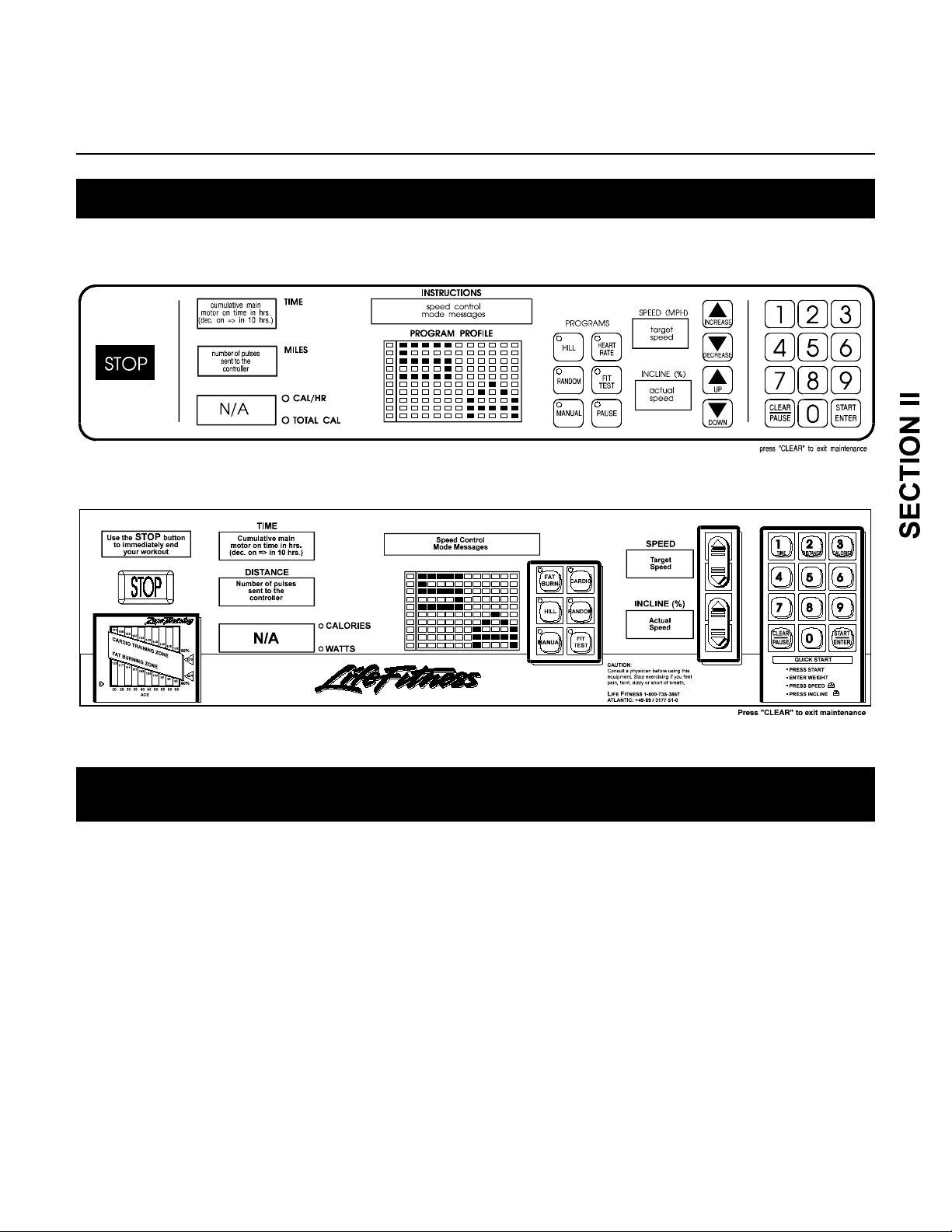
DIAGNOSTIC TESTS
How To...EXECUTE THE SERVICE MODE
WARNING: DO NOT STAND ON THE STRIDING BELT WHILE ENTERING THE SERVICE
MODE OR WHILE PERFORMING ANY OF THE DIAGNOSTIC TESTS.
NOTE: TO ACCESS A SPECIFIED DIAGNOSTIC PROGRAM, USE THE PROGRAM KEYS.
A PROGRAM KEY IS CONSIDERED "ON" WHEN ITS LED IS LIT, "OFF" WHEN IT IS NOT LIT.
THE DISPLAY PROGRAM LED’s SHOWN ON THESE EXAMPLES ARE "OFF".
TO ENTER THE DIAGNOSTIC / ACCOUNTING TEST:
1. Press the START key once.
2. Press the CLEAR key twice.
3. Press the number keys 9 - 1 - 9.
4. Press the ENTER key.
IF THE TREADMILL IS CONNECTED TO A LIFECENTER SYSTEM:
1. Press the START key once.
2. Press the CLEAR key twice.
3. Press the MANUAL program key.
4. Press the number keys 9 - 1 - 9.
5. Press the ENTER key.
1
Page 22
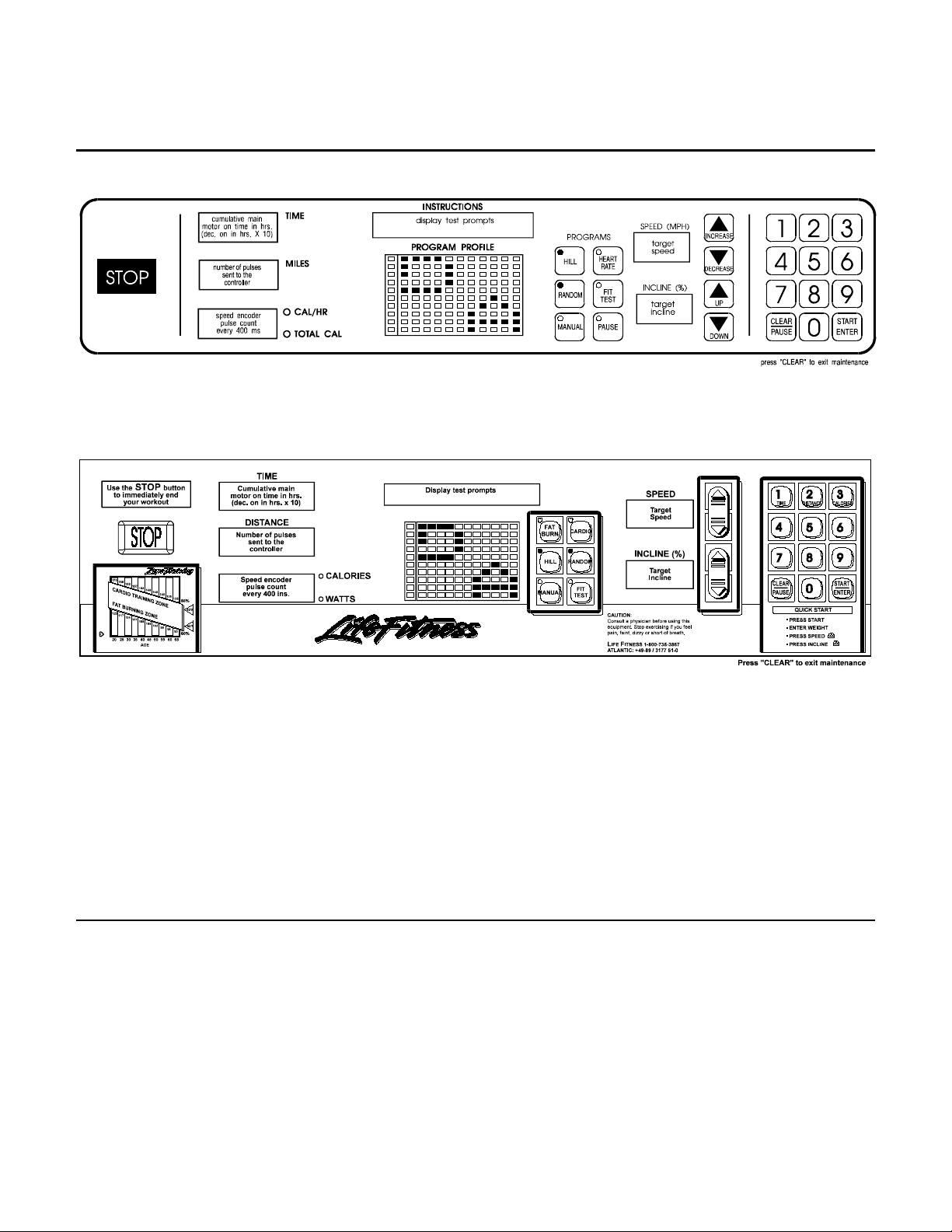
Life Fitness 9100 Series Heartrate and Telemetry Equipped Treadmills
DIAGNOSTIC TESTS
How To...EXECUTE THE DISPLAY TEST
This test indicates if the Display is working properly.
TO ENTER INTO THE DISPLAY TEST TURN "ON" THE HILL AND RANDOM KEYS
The information that will be displayed in this mode is as follows:
± Lit LED's displayed in all windows.
± Walking LED's displayed in all windows.
± Hours that main motor has been working displayed in TIME window.
± Speed encoder count displayed in CALORIES window .
± Speed pulse count displayed in MILES (KILOMETERS) window.
± Target speed indicated in SPEED window.
± Target incline indicated in INCLINE window.
Tests in the Display Diagnostics are as follows:
1. Press the ENTER key once to test Displays LED's.
Press the ENTER key twice to test Display Walking LED's.
2. After pressing the ENTER key once, press Number Keys to view specific digits.
3. Press INCLINE and SPEED keys to view specific number segments.
4. Press CLEAR to exit the Diagnostic Program or press Program Keys to enter another
Diagnostic/Accounting function.
2
Page 23
Life Fitness 9100 Series Heartrate and Telemetry Equipped Treadmills
DIAGNOSTIC TESTS
How To...EXECUTE THE EEPROM MODE
This test indicates the amount of memory and allows for changes in the program times.
TO ENTER INTO THE TEST TURN "ON" THE HILL, RANDOM AND FIT TEST PROGRAM KEYS.
The information that will be displayed in this mode is as follows:
± Statistics and software code version will be displayed in the INSTRUCTIONS window.
± Speed encoder count displayed in CALORIES window.
± Speed pulse count displayed in MILES (KILOMETERS) window.
± Software options are displayed in INSTRUCTIONS window.
± Optional settings displayed in the INSTRUCTIONS window.
You may change Program times by pressing the ENTER key when the Program time is indicated on the
INSTRUCTIONS window. Default time is set at 60 Minutes and can be reset from 1 to 99 Minutes.
You may change the maximum pr ogram m able belt speed by pressing the speed INCREASE and DECREASE keys
when the MAXIMUM SPEED m essage is dis played in the INSTRUCTIONS window. The choices f or m axim um belt
speeds are 10.0 mph (11.6 kpm) to 2.0 mph (3.22 kph) in 0.5 mph (0.805 kph) increments.
You may change the minimum speed between 1.0 mph (1.61 kph) and 1.5 mph (2.415 kph) using the speed
INCREASE and DECREASE keys.
Press the CLEAR key to exit the Diagnostic Program or press Program keys to enter another Diagnostic/Accounting
function.
3
Page 24
Life Fitness 9100 Series Heartrate and Telemetry Equipped Treadmills
DIAGNOSTIC TESTS
How To...EXECUTE THE INCLINE CONTROL TEST
This test indicates if the unit is reaching or lowering to the user's chosen level.
TO ENTER INTO THE INCLINE CONTROL TEST TURN "ON" THE HILL PROGRAM KEY.
The information that will be displayed in this mode is as follows:
± How long lift action has been on in minutes. Displayed in TIME window.
± Lift position counts displayed in INSTRUCTIONS window.
± Speed encoder count displayed in CALORIES window.
± Target incline indicated in SPEED window.
± Actual incline indicated in INCLINE window.
NOTE: INCLINE NUMBERS SHOULD BE EQUAL.
Tests in the Incline Control Diagnostics are as follows:
1. Press INCLINE keys to target incline.
2. Press the SPEED or NUMBER keys to enter a target speed.
3. Press the ENTER or " 0 " key to stop the striding belt.
4. Press CLEAR to exit the Diagnostic Program or press Program Keys to enter another
Diagnostic/Accounting function.
4
Page 25
Life Fitness 9100 Series Heartrate and Telemetry Equipped Treadmills
DIAGNOSTIC TESTS
How To...EXECUTE VIEWING OF USAGE STATISTICS
This mode supplies statistics and code versions of the Treadmill.
TO ENTER INTO THE VIEWING OF USAGE STATISTICS TESTS
TURN "ON" THE RANDOM AND FIT TEST PROGRAM KEYS
The information that will be displayed in this mode is as follows:
± Statistics and software code version displayed in the INSTRUCTIONS window.
± Speed encoder count displayed in CALORIES window.
± Speed pulse count displayed in MILES (KILOMETERS) window.
± Target speed indicated in SPEED window.
± Target incline indicated in INCLINE window.
5
Page 26
Life Fitness 9100 Series Heartrate and Telemetry Equipped Treadmills
DIAGNOSTIC TESTS
How To...EXECUTE THE WAXER CONTROL TEST
This test indicates the status of the waxing system.
TO ENTER INTO THE TEST TURN "ON" THE FIT TEST PROGRAM KEY.
The information that will be displayed in this mode is as follows:
± Percent of wax left in reservoir displayed in the INSTRUCTIONS window.
± Number of times the wax pump has discharged displayed in INSTRUCTIONS window.
± Hours since last waxing displayed in the TIME window.
± Waxing duration displayed in the CALORIES window.
± Waxing interval displayed in the MILES (KILOMETERS) window.
± Target speed indicated in SPEED window.
± Target incline indicated in INCLINE window.
Tests in the Waxing Control Diagnostics ar e as follows:
1. Press the ENTER key to start waxing operation.
2. Press the SPEED or NUMBER keys to enter a target speed.
3. Press the INCLINE/DECLINE keys to enter a target incline.
4. Press the " 0 " key to stop the striding belt.
5. Press CLEAR to exit the Diagnostic Program or press Program Keys to enter another
Diagnostic/Accounting function.
6
Page 27

Life Fitness 9100 Series Heartrate and Telemetry Equipped Treadmills
DIAGNOSTIC TESTS
How To...EXECUTE THE HEART RATE MONITORING MODE
This test indicates if the heart rate pr ogram is operating properly.
TO ENTER INTO THE TEST TURN "ON" THE HEART RATE PROGRAM KEY.
The information that will be displayed in this mode is as follows:
± Hands "ON" condition indicated on TOTAL CALORIE LED.
± Sensor connection "GOOD" indicated on CALORIE/HOUR LED.
± Amplification factor for heart signal displayed in TIME window.
± Heart rate from HR Monitor displayed in CALORIES window.
± Target speed indicated in SPEED window.
± Target incline indicated in INCLINE window.
± Heart rate indicated in INSTRUCTION window.
To test the Heart Rate Monitor:
1. Place hands on the handlebar sensors.
2. Read INSTRUCTION window.
7
Page 28

Life Fitness 9100 Series Heartrate and Telemetry Equipped Treadmills
DIAGNOSTIC TESTS
How To...EXECUTE THE SPEED CONTROL OPERATION TEST
This test indicates if the unit is running at the actual speed that the user has chosen.
TO ENTER INTO THE TEST ALL PROGRAM KEYS SHOULD BE IN THE “OFF” POSITION.
The information that will be displayed in this mode is as follows:
± Total main motor on time in hours is displayed in the TIME window.
± Total number of electrical pulses sent to the motor controller is displayed in the MILES (KILOMETERS)
window.
± Total main motor on time in hours and total main motor miles are displayed in the INSTRUCTIONS window.
± Target speed indicated in SPEED window.
± Actual speed indicated in INCLINE window.
± Energy pulses being sent to motor from motor controller are displayed on CALORIE\HOUR LED.
± Actual speed and target speed matched are displayed on TOTAL CALORIE LED.
Tests in the Speed Control Diagnostics are as follows:
1. Press the speed INCREASE\DECREASE keys to enter target speed.
2. Examine target and actual speed windows to verify equal speeds.
3. Press the ENTER or " 0 " key to stop the striding belt.
4. Press CLEAR to exit the Diagnostic Program or press Program Keys to enter another
Diagnostic/Accounting function.
8
Page 29

Life Fitness 9100 Series Heartrate and Telemetry Equipped Treadmills
How To...REMOVE AND REPLACE THE ANTI-SCUFF PADS
Tools Required: Pencil, non-abrasive cleaner, paper towels
Step 1
Use a pencil to draw an outline of the upper corners of the worn ANTI-SCUFF PAD on the FRAME.
Step 2
Peel the worn ANTI-SCUFF PAD from the FRAME and clean the residue with non-abrasive cleaning solution and
paper towels.
Step 3
Peel the protective backing from the new ANTI-SCUFF PAD.
Step 4
Align the top two corners of the new ANTI-SCUFF PAD with the lines drawn in Step 1 and press in place.
NOTE: TO AVOID AIR BUBBLES, THE TOP TWO CORNERS MUST BE ALIGNED EXACTLY
BEFORE PRESSING DOWN THE ENTIRE ANTI-SCUFF PAD.
Step 5
Press the remainder of the new ANTI-SCUFF PAD against the FRAME SIDE PANEL. Star t at the top and apply
even pressure downward to the bottom keeping an even distance to the edge of the STRIDING BELT.
NOTE; IN THE EVENT OF AIR BUBBLES, USE A SCRIBE TO MAKE A SMALL HOLE IN THE AIR BUBBLE,
THEN PRESS THE PAD DOWN AGAINST THE FRAME PANEL UNTIL THE AIR BUBBLE IS GONE.
1
Page 30

Life Fitness 9100 Series Heartrate and Telemetry Equipped Treadmills
How To...REMOVE AND REPLACE THE DEBRIS BRUSH
Tools Required: Short phillips screwdriver
Step 1
Turn the power OFF at the switch and by unplugging the unit at the electrical outlet.
Step 2
Carefully tilt the treadmill on its side.
NOTE: INSPECT THE AREA BETWEEN THE STRIDING BELT FOR DEBRIS.
Step 3
Remove the two SCREWS, LOCKNUTS and WASHERS securing the DEBRIS BRUSH to the BRACKETS.
Step 4
Position the new DEBRIS BRUSH between the STRIDING BELT and FRAME. Insert the SCREW through the
BRACKET with the round hole first. Secure in place with a W ASHER and LOCKNUT . Repeat procedure to secure
the DEBRIS BRUSH to the slotted BRACKET side.
Step 5
Reverse Steps 1 and 2 to return all parts to their proper positions.
2
Page 31

Life Fitness 9100 Series Heartrate and Telemetry Equipped Treadmills
How To...REMOVE AND REPLACE THE ANTI-STATIC CORDS
Tools Required: Needle-nose pliers
ATTENTION: THE 9100 TREADMILL HAS TWO ANTI-STATIC CORDS. ONE IS LOCATED
BEHIND/BETWEEN THE STRIDING BELT, THE OTHER BENEATH. EITHER OF THESE
TWO MAY BREAK OR REQUIRE REPLACEMENT.
Step 1
Turn the power OFF at the switch and by unplugging the unit at the electrical outlet.
Step 2
Carefully tilt the unit on its side.
NOTE: INSPECT THE AREA BETWEEN THE STRIDING BELT FOR DEBRIS.
Step 3
Both ANTI-STATIC CORDS ar e equipped with an eyelet on one end and a spring on the other. Unhook the spring
end of the CORD from the bracket first, to avoid snap back, and then unhook the eyelet end.
Step 4
Install the new ANTI-STATIC CORD eyelet end first.
Step 5
Reverse Steps 1 and 2 to restore unit to operation.
3
Page 32

Life Fitness 9100 Series Heartrate and Telemetry Equipped Treadmills
How To...REMOVE AND REPLACE THE DECK
Tools Required: Hex key wrench set, socket and ratchet set
ATTENTION: IF THE DECK IS TO BE REPLACED OR FLIPPED TO AN UNUSED SIDE, THE STRIDING BELT
MUST BE REPLACED AT THIS TIME. IF THE DECK IS TO BE FLIPPED, WIPE THE UNUSED SURFACE
CLEAN WITH SOAP AND WATER PRIOR TO INSTALLATION.
Step 1
Turn the power OFF at the switch and by unplugging the unit at the electrical outlet.
NOTE: THE TENSION OF THE STRIDING BELT MUST BE SLACKENED TO ALLOW ACCESS TO THE DECK.
Step 2
Use a 9/16" socket and ratchet wrench to ALTERNATELY AND EQUALLY turn the two BELT TENSIONING
BOLTS counter-clockwise until the STRIDING BELT is sufficiently slackened.
Step 3
Once the STRIDING BELT has been s lack ened, rem ove the corner four MOUNT ING SCREWS and the center f our
DECK STIFFENER SCREWS.
Step 4
Carefully lift the worn DECK and remove it from the m achine. Transfer the two PINCH CLEATS to the new DECK or
the unused side of the existing DECK and slide the DECK into place.
Step 5
Insert and tighten the corner four MOUNTING SCREWS and the four DECK STIFFENER SCREWS.
Step 6
Manually position the STRIDING BELT in the center of the ROLLERS. Retension the STRIDING BELT by
ALTERNATELY AND EQUALLY turning the two BELT TENSIONING BOLT S clock wise until the ST RIDING BELT
seems snug against the REAR ROLLER.
WARNING: DO NOT OVERTIGHTEN THE STRIDING BELT TENSIONING BOLTS TO AVOID POSSIBLE
DAMAGE TO THE STRIDING BELT AND THE ROLLER BEARINGS.
Step 7
Plug the cord into the electrical outlet and turn the unit ON at the switch.
Step 8
Enter the Manual Program and set the BELT speed to 4.0 mph ( 6.4 kph). If the STRIDING BELT rem ains centered
after 5 minutes proceed to Step 9. If the STRIDING BELT drifts to the left or right, see "How To...Adjust and Tension
the Striding Belt".
Step 9
Set the BELT speed at 2.0 mph (3.2 k ph). Tightly grasp the HANDRAILS and attempt to stall the STRIDING BELT.
If the STRIDING BELT does not slip, the unit is ready to return to service. If the STRIDING BELT does slip, see
"How To...Adjust and Tension the Striding Belt" for proper BELT retensioning procedures.
Continued
4
Page 33

Life Fitness 9100 Series Heartrate and Telemetry Equipped Treadmills
How To...REMOVE AND REPLACE THE DECK (Continued)
5
Page 34

Life Fitness 9100 Series Heartrate and Telemetry Equipped Treadmills
How To...REMOVE AND REPLACE THE TRANSFORMER
Tools Required: Standard screwdriver, hex key wrench set, wire cutting tool
Step 1
Turn the power OFF at the switch and by unplugging the unit at the electrical outlet.
Step 2
Remove the four SCREWS securing the MOTOR COVER in place and set COVER aside.
Step 3 (Figure 1)
Pull out the two RUBBER MOUNTING NUTS holding the FRONT PRO TECTOR SHIELD in position and rem ove it
from the machine.
Step 4 (Figure 1)
Remove the four SCREWS securing the FRONT COVER in place.
Step 5
Unplug the two CONNECTORS and cut any WIRE TIES securing the worn TRANSFORMERS' WIRE HARNESS to
the Treadmill FRAME.
Step 6 (Figure 2)
Remove the two SCREWS securing the worn TRANSFORMER to the POWER BOX and replace with a new
TRANSFORMER.
Step 7
Reverse Steps 1 through 5 to return all parts to their proper position.
NOTE: BE SURE TO REPLACE ALL WIRE TIES TO SECURE THE WIRE HARNESS
TO THE FRAME IN ITS ORIGINAL POSITION.
6
Page 35

Life Fitness 9100 Series Heartrate and Telemetry Equipped Treadmills
How To...REMOVE AND REPLACE THE LIFESPRINGS
Tools Required: Hex key wrench set, socket and ratchet set
Step 1
Turn the power OFF by unplugging the unit at the wall outlet.
Step 2
Remove the DECK (See "How To...").
Step 3
Remove the two DECK CHANNELS and set them aside to be reinstalled later.
Step 4
Remove the SCREW and W ASHER securing each
worn LIFESPRING to the FRAME.
Step 5
Insert the SCREW and W ASHER into the hole in the new LIFESPRING. Position the LIFESPRING ASSEMBLY in
place on the FRAME and secure.
Step 6
Slide the two DECK CHANNELS back into place.
Step 7
Reverse Steps 1 and 2 to return all parts to their proper positions.
NOTE: APPLY LOCTITE TO THE SCREW PRIOR TO
SECURING THE NEW LIFESPRING INTO POSITION TO
AVOID ANY POSSIBLE LOOSENING OF THE SCREW.
7
Page 36

Life Fitness 9100 Series Heartrate and Telemetry Equipped Treadmills
How To...REMOVE AND REPLACE THE PC CONTROL BOARD
Tools Required: Standard and phillips screwdriver, hex key wrench set
Step 1
Enter into the Service Menu, with the existing PC CONTROL BOARD s till in place, by pressing 9-1- 9, ENT ER. With
all the Program Keys OFF (0000), record the total number of unit hours in use displayed on the CONSOLE.
Step 2
Press the Fit Test Program Key (0001) and record the total number of times the WAX MOTOR/PUMP has
discharged while unit has been in operation.
Step 3
Turn the power OFF by unplugging the unit at the wall outlet.
Step 4
Remove the four SCREWS securing the MOTOR COVER in place and set the MOTOR COVER aside.
Step 5
Pull out the two RUBBER MOUNTING NUTS holding the FRONT PRO TECTOR SHIELD in position and rem ove it
from the machine.
Step 6
Remove the four SCREWS securing the FRONT COVER in place.
Step 7
Ground yourself by positioning an ANTI-STATIC ST RAP around your wrist and attaching the other end (alligator
clip) to the machine FRAME.
Step 8
Loosen, but do not remove, the two SCREW S at the bottom of the PC CONTRO L BOARD ASSEMBLY. Pop open
the two PLASTIC RIVETS at the top of the assem bly with a standard screwdriver. Swing down the top of the PC
CONTROL BOARD ASSEMBLY and lift the entire ASSEMBLY away from the FRAME.
Step 9
Unplug the seven CONNECTORS from the PC CONTROL BOARD, taking note of their locations.
Step 10
With a phillips screwdriver, loosen and rem ove the six SCREW S securing the worn PC CONTROL BO ARD to the
MOUNTING BRACKET. Install the new PC CONTROL BOARD, reinsert and tighten the six SCREWS.
Step 11
Reverse Steps 5 through 9 to return all parts to their proper positions.
Step 12
Disconnect the WAX MOTOR/PUMP plug from the electrical connector located on the left side of the FRONT
FRAME ASSEMBLY.
Step 13
Turn the power ON by plugging the unit in at the wall outlet. The DISPLAY CONSOLE will read "Waxer is
Unplugged". Press ENTER twice.
Continued
8
Page 37

Life Fitness 9100 Series Heartrate and Telemetry Equipped Treadmills
How To...REMOVE AND REPLACE THE PC CONTROL BOARD ( Continued )
__________________________________________________________________________________ _
Step 14
Enter into the Service Menu by pressing 1-0-1, ENTER.
Step 15
Press the FIT TEST Program Key (0001) and then press the ENTER key the total number of times the WAX
MOTOR/PUMP had previously discharged with the worn PC CONTROL BOARD in operation.
Step 16
Alternately press the Hill and Random Program Keys (1101) and c heck the WAX DELAY "OFF" or "ON" reading
displayed on the CONSOLE. If the previous total number of unit hour s was 100 hours or more, pres s the Speed
INCREASE Key until the WAX DELAY reads "OFF".
Step 17
Turn the power OFF at the switch and by unplugging the unit at the electrical outlet.
Step 18
Reconnect the WAX MOTOR/PUMP plug to the electrical connector on the left side of the FRONT FRAME
ASSEMBLY.
Step 19
Reverse Steps 3 and 4 to return the unit to operation.
9
Page 38

Life Fitness 9100 Series Heartrate and Telemetry Equipped Treadmills
How To...REMOVE AND REPLACE THE DISPLAY CONSOLE
Tools Required: Phillips screwdriver, hex key wrench set
Step 1
Turn the power OFF at the ON/OFF switch and by unplugging the machine at the electrical outlet.
Step 2
Remove the four SCREWS securing the CONNECTOR COVER to the bottom of the DISPLAY CONSOLE.
Step 3
Unplug the 10-PIN CONNECTOR and the 4-PIN CONNECTOR from the back of the DISPLAY CONSOLE.
Step 4
Remove the four SCREWS securing the DISPLAY CONSOLE to the HANDRAILS.
Step 5
Rest the new DISPLAY CONSOLE on the HANDRAILS, then install and tighten the four STARWASHERS,
WASHERS and SCREWS in a criss-cross pattern to secure it in place. Do not overtighten the screws.
NOTE: BE CAREFUL NOT TO PINCH ANY WIRES BETWEEN THE
DISPLAY CONSOLE AND THE BRACKETS.
Step 6
Reverse Steps 1 through 3 to complete installation.
10
Page 39

Life Fitness 9100 Series Heartrate and Telemetry Equipped Treadmills
How To...REMOVE AND REPLACE THE STOP SWITCH
Step 1
Turn the power OFF at the ON/OFF switch and by unplugging the machine at the electrical outlet.
Step 2
Remove the DISPLAY CONSOLE from the machine (See “How To...”).
Step 3
Remove the BEZEL ( FACE PLATE ) from the DISPLAY CONSOLE.
Step 4
Disconnect the wiring from the worn STOP SWITCH.
Step 5
Remove the worn STOP SWITCH from the BEZEL ASSEMBLY. Depending on the type of switch previously used, it may be
necessary to damage the existing STOP SWITCH to acccomplish this task. Take special care not to cause damage to the BEZEL
ASSEMBLY during this procedure.
Step 6
Insert the STOP SWITCH BODY through the opening in the front of the BEZEL ASSEMBLY taking note to orient the SWITCH
BODY so the word “STOP” is readable from the face of the BEZEL.
Step 7
Slide the locking CLIP from the rear of the BEZEL over the SWITCH BODY.
Step 8
Install the plastic NUT on to the threaded portion of the SWITCH BODY with the flat side toward the BEZEL and tighten 1/8 of a turn
past hand tight. (Torque 10-15 in/lbs.)
CAUTION: OVERTIGHTENING THE NUT MAY CAUSE DAMAGE TO THE SWITCH BODY OR THE BEZEL.
Step 9
Bend each of the two LOCKING CLIP TABS of the LOCKING CLIP 90 degrees to secure the NUT into position and prevent it from
rotating. It may be necessary to back off the NUTslightly to insure that the tabs come in contact with a flat spot on the NUT. The
LOCKING CLIP TABS can sustain being bent several times to insure a tight lock.
Step 10
Insert the SWITCH into the SWITCH BODY taking special note to orient the two parts so the SWITCH PLUNGERS make contact
upon assembly. DO NOT bend the CONNECTOR TABS on the switch.
NOTE: VERIFY THAT THE PLUNGERS ARE MAKING CONTACT BY PRESSING THE STOP BUTTON AND VISUALLY
INSURING THEY TOUCH EACH OTHER. A CLICKING SOUND WILL BE HEARD FROM
THE SWITCH IF THE ASSEMBLY HAS BEEN INSTALLED PROPERLY.
Step 11
Reconnect the wiring being extremely careful not to bend or break the connecting tabs of the switch and reverse Steps 1
through 3 to return all parts to their proper position.
11
Page 40

Life Fitness 9100 Series Heartrate and Telemetry Equipped Treadmills
How To...REMOVE AND REPLACE THE TELEMETRY / HR KIT
Tools Required: Phillips screwdriver
Step 1
Turn the power OFF at the ON/OFF switch and by unplugging the machine at the electrical outlet.
Step 2
Use a Phillips screwdriver to loosen and remove the two SCREWS securing the TELEMETRY/HEART RATE
SENSOR COVER to the bottom of the CONSOLE PAN.
Step 3
Gently pull on the WIRE HARNESS protruding f rom the CONSO LE PAN to provide s om e s lack in the line. Rem ove
the TELEMETRY/HEART RATE RECEIVER f rom within the protective foam and unplug the RECEIVER from the
receptacle on the WIRE HARNESS.
Step 4
Install the new TELEMETRY/HEART RATE RECEIVER by reversing Steps 1 through 3 to return all parts to their
proper position.
NOTE: BE CAREFUL NOT TO PINCH ANY WIRES BETWEEN THE CONSOLE PAN AND
THE TELEMETRY/HEART RATE SENSOR COVER DURING INSTALLATION.
12
Page 41

Life Fitness 9100 Series Heartrate and Telemetry Equipped Treadmills
How To... REMOVE AND REPLACE THE HANDRAILS
Tools Required: Phillips screwdriver, hex key wrench set, socket and ratchet set
Step 1
Turn the power OFF at the ON/OFF switch and by unplugging
the machine at the electrical outlet
Step 2
Remove the DISPLAY CONSOLE (See "How To...").
Step 3
Loosen and remove the three SCREWS securing the
HANDLEBAR FLANGE to the HANDRAIL you are
replacing.
.
Step 4
To replace the RIGHT HANDRAIL simply remove the two BOLTS from the base of the worn HANDRAIL and lift it away
from the machine. Proceed to Step 5.
To replace the LEFT HANDRAIL remove the two BOLTS from the base of the worn HANDRAIL and very carefully tilt
the HANDRAIL away from the machine to allow removal of the HANDLEBAR HEART RATE WIRE HARNESS from the
top of the HANDRAIL. Slowly lift the HANDRAIL and unplug the 10 PIN CONNECTORS located between the base of the
HANDRAIL and the Treadmill FRAME. Set the HANDRAIL down away from the machine.
Step 5
If you have removed the LEFT HANDRAIL, carefully withdraw the
DISPLAY WIRE HARNESS from the worn HANDRAIL and transf er
it to the new HANDRAIL.
Step 6
Remove the two HANDRAIL ENDCAPS from the worn HANDRAIL
and transfer them to the new HANDRAIL (if not included.
Step 8
Reverse Steps 1 through 4 to return all parts to their proper
position.
NOTE: BE CAREFUL NOT TO PINCH ANY WIRES BETWEEN
PARTS DURING ASSEMBLY OF THE TREADMILL.
13
Page 42

Life Fitness 9100 Series Heartrate and Telemetry Equipped Treadmills
How To...REMOVE AND REPLACE THE HANDLEBAR
Tools Required: Phillips screwdriver, hex key wrench set, socket and ratchet set
Step 1
Turn the power OFF at the ON/OFF switch and by unplugging the machine at the electrical outlet.
Step 2
Remove the DISPLAY CONSOLE (See "How To...").
Step 3
Loosen, but do not remove, the two BOLTS securing the base of the RIGHT HANDRAIL to the Treadmill FRAME.
Step 4
Remove the six SCREW S securing the HANDLEBAR to the two HANDRAILS. On m odels equipped with Lifepulse
sensors, withdraw the HANDLEBAR WIRE HARNESS with the 4 PIN CONNECTOR from the user LEFT
HANDRAIL. Lift out and remove the HANDLEBAR.
Step 5
Grasp the new HANDLEBAR, and with the WIRE HARNESS to the lef t on m odels equipped with Lif epulse sensor s,
route the WIRE HARNESS through the opening in the LEFT HANDRAIL, exiting alongside the other WIRE
HARNESS. Align the three holes in the HANDLEBAR FLANGE with those in the LEFT HANDRAIL and re-install the
SCREWS. Repeat on the right side.
Step 6
Reverse Steps 1 through 4 to return the Treadmill to operation.
14
Page 43

Life Fitness 9100 Series Heartrate and Telemetry Equipped Treadmills
How To...REMOVE AND REPLACE THE WAX MOTOR/PUMP
Tools Required: Standard screwdriver, vise grips or clamp, hex key wrench set, socket and ratchet set
Step 1
Turn the power OFF at the switch and by unplugging the unit at the electrical outlet.
Step 2
Separate the FRONT and REAR FRAME ASSEMBLIES (See "How To...").
Step 3
Disconnect the 2-PIN CONNECTOR leading to the worn WAX MOTOR/PUMP.
Step 4
With your fingers, remove the HOSE CLAMP leading from the WAX CONTAINER and temporarily seal off the
HOSE to prevent spillage while disconnecting it.
Step 5
Remove the SPRING CLAMP and HOSE leading to the SPRAY NOZZLE.
Step 6
Use a wrench to loosen and remove the four MOUNTING BOLTS and WASHERS securing the worn WAX
MOTOR/PUMP to the FRAME and replace with a new WAX MOTOR/PUMP.
NOTE: THIS IS NORMALLY AN OPPORTUNE TIME TO INSPECT THE WAX SPRAY NOZZLE. SLIDE
YOUR HAND BETWEEN THE BOTTOM OF THE FRAME AND THE STRIDING BELT. PRESS THE
SPRAY NOZZLE IN AND TWIST IT 1/4 TURN TO REMOVE. CLEAN OR REPLACE THE
SPRAY NOZZLE AS DEEMED NECESSARY.
Step 7
Reverse Steps 1 through 5 to return all parts to their proper positions taking special note to unkink the WAX
CONTAINER HOSE prior to rejoining the FRONT and REAR FRAME ASSEMBLIES.
15
Page 44

Life Fitness 9100 Series Heartrate and Telemetry Equipped Treadmills
How To...REMOVE AND REPLACE THE DRIVE MOTOR
Tools Required: Standard screwdriver, hex key wrench set, straightedge
Step 1
Turn the power OFF at the switch and by unplugging the unit at the electrical outlet.
Step 2
Remove the four SCREWS securing the MOTOR COVER in place and set COVER aside.
Step 3 (Figure 1)
Insert a standard screwdriver into the slot on the f ront of the IDLER LEVER and lift upwards to relieve tension f rom
the DRIVE MOTOR BELT. Remove BELT from the DRIVE MOTOR PULLEY.
Step 4
Disconnect the 6-PIN CONNECTOR of the DRIVE MOTOR HARNESS and remove the CONNECT OR from the
bracket securing it to the FRAME.
Step 5 (Figure 2)
Remove the two SCREWS and NUTS securing the HOLD DOW N CLAMPS at the front and rear of the DRIVE
MOTOR.
Step 6
Lift the entire DRIVE MOTOR ASSEMBLY off of the FRAME CRADLE and remove it from the machine.
Step 7 (Figure 2)
Loosen the two SET SCREWS securing the DRIVE MOTOR PULLEY to the MOTOR SHAFT and transfer the
DRIVE MOTOR PULLEY from the worn DRIVE MOT OR to the new. (Do not tighten the the SET SCREW S at this
time.)
Step 8
Partially reassemble the DRIVE MOTOR ASSEMBLY by reversing Steps 3 through 6.
Step 9 (Figure 2)
Use a straightedge to align the DRIVE MOTOR PULLEY with the FRONT ROLLER PULLEY. Once the alignment is
exact, tighten the two SET SCREW S on the DRIVE MOT OR PULLEY to secure it to the SHAFT of the new DRIVE
MOTOR.
Step 10
Reverse Steps 1 and 2 to return the unit to operation.
16
Continued
Page 45

Life Fitness 9100 Series Heartrate and Telemetry Equipped Treadmills
How To...REMOVE AND REPLACE THE DRIVE MOTOR (Continued)
17
Page 46

Life Fitness 9100 Series Heartrate and Telemetry Equipped Treadmills
How to...SEPARATE THE FRONT AND REAR FRAME ASSEMBLIES
Tools Required: Standard screwdriver, hex key wrench set, socket and ratchet set
Step 1
Turn the power OFF at the switch and by unplugging the unit at the electrical outlet.
Step 2
Remove the four SCREWS securing the MOTOR COVER in place and set COVER aside.
Step 3
Remove the four SCREWS securing the two REAR FRAME CAPS in position as well as the two SCREWS located
on top of the SIDE PANELS above the REAR FRAME CAPS.
Step 4
Loosen, but do not remove, the two SCREWS securing the base of the right side HANDRAIL to the SIDE PANEL.
Step 5
Carefully tilt the unit on to its left side.
Step 6 (Figure 1)
Remove or loosen, but do not remove, the FRAME and SIDE PANEL BOLTS as designated in the Figure 1
diagram.
Step 7
Slowly tilt the unit back to its normal operating position.
Step 8 (Figure 2)
Grasp the right hand SIDE PANEL and pull it away from the machine along its entire length to provide c learance f or
the FRONT ROLLER pulley.
Step 9 (Figure 2)
Insert a standard screwdriver into the slot on the f ront of the IDLER LEVER and lift upwards to relieve tension f rom
the DRIVE MOTOR BELT. Remove BELT from the DRIVE MOTOR pulley.
Step 10 (Figure 2)
Disconnect the WAX MOTOR/PUMP plug from the electrical outlet located on the left side of the frame.
Step 11 (Figure 2)
Grasp the REAR FRAME at each end of the REAR ROLLER and pull outward to separ ate the FRONT and REAR
FRAME ASSEMBLIES.
Step 12
Reverse Steps 1 through 11 to return all parts to their proper positions.
REASSEMBLY TIME SAVING TIP: WHEN SLIDING THE REAR FRAME ASSEMBLY BACK INTO POSITION
USE A SLIGHT SIDE TO SIDE ROCKING MOTION TO OVERCOME ANY HIGH SPOTS WITHIN THE
SIDE PANELS. ONCE THE REAR FRAME IS SET FIRMLY IN POSITION AGAINST THE STOP PINS,
INSERT AND LOOSELY INSTALLTHE FOUR FRAME BOLTS BEFORE TILTING THE
MACHINE ON ITS SIDE AT STEP 7 AS YOU REVERSE THE STEPS.
18
Continued
Page 47

Life Fitness 9100 Series Heartrate and Telemetry Equipped Treadmills
How To...SEPARATE THE FRONT AND REAR FRAME ASSEMBLIES (Continued)
19
Page 48

Life Fitness 9100 Series Heartrate and Telemetry Equipped Treadmills
How To...REMOVE AND REPLACE THE STRIDING BELT
Tools Required: Standard screwdriver, hex key wrench set, socket and ratchet set
CAUTION: DO NOT REMOVE OR LOOSEN THE FRONT ROLLER WHENEVER REMOVING OR
INSTALLING A NEW OR EXISTING STRIDING BELT.
Step 1
Turn the power OFF at the switch and by unplugging the unit at the electrical outlet.
Step 2
Separate the FRONT and REAR FRAME ASSEMBLIES ("See How To...").
Step 3 (Figure 1)
Remove the two BELT TENSIONING BOLTS and WASHERS from the REAR ROLLER.
Step 4 (Figure 1)
Remove the two SCREWS securing the left side ROLLER GUIDE BRACKET in position.
Step 5 (Figure 1)
Remove the SCREW and PINCH CLEAT from the left side of the DECK.
Step 6 (Figure 1)
Remove the SCREW and W ASHER securing the TOE GUARD to the left s ide of the FRAME. Loosen, but do not
remove, the SCREW and WASHER securing the TOE GUARD to the right side of the FRAME.
Step 7
Lift the REAR ROLLER up, forward and to the left to completely remove it from between the FRAME and the
STRIDING BELT.
Step 8
With the REAR ROLLER removed from the unit, tilt the REAR FRAME ASSEMBLY on to its right side.
Step 9 (Figure 2)
Unhook the top SPRING of the ANTI-ST ATIC CORD on the outside of the STRIDING BELT and allow it to drop to
the floor.
Step 10 (Figure 2)
Manuever the worn STRIDING BELT over the FRONT ROLLER and the rear of the FRAME. Install the new
STRIDING BELT while taking spec ial care to insure the ARROW S stam ped on the underside of the BELT point in
the direction of machine rotation. If the STRIDING BELT bears the Life stride Logo it should be r eadable to a person
using the treadmill for proper rotation.
Step 11
Reverse Steps 1 through 10 to return all parts to their pr oper position. (Do not reinstall the REAR FRAME CAPS at
this time unless they are equipped with BELT TENSIONING BOLT access holes).
Step 12
Adjust and tension the STRIDING BELT (See “How To...).
20
Continued
Page 49

Life Fitness 9100 Series Heartrate and Telemetry Equipped Treadmills
How To...REMOVE AND REPLACE THE STRIDING BELT (Continued)
21
Page 50

Life Fitness 9100 Series Heartrate and Telemetry Equipped Treadmills
How To...REMOVE AND REPLACE THE LIFT ACTUATOR
Tools Required: Hex key wrench set, two 9/16" wrenches, wire cutting tool
Step 1
Turn the power OFF at the switch and by unplugging the unit at the electrical outlet.
Step 2
Temporarily remove the PC CONTROL BOARD ASSEMBLY (See "How To..." and follow Steps 2 through 6 only).
Step 3
Cut the WIRE TIES and unplug the 4-PIN CONNECT OR of the LIFT ACTUATOR WIRE HARNESS from the PC
CONTROL BOARD.
Step 4
Carefully tilt the Treadmill on its right side.
Step 5
Remove the BOLT and NUT securing the bottom of the LIFT ACTUATOR to the FRAME WHEEL ASSEMBLY.
Step 6
Remove the HAIRPIN CLIP and CLEVIS PIN securing the top of the LIFT ACTUATOR to the FRAME and angle the
worn unit toward the front to remove it from the machine.
Step 7
Install the new LIFT ACTUATOR by reversing Steps 1 through 6.
NOTE: BE SURE TO REPLACE ALL WIRE TIES TO SECURE THE
WIRE HARNESS IN ITS ORIGINAL POSITION.
22
Page 51

Life Fitness 9100 Series Heartrate and Telemetry Equipped Treadmills
How To...REMOVE AND REPLACE THE MOTOR CONTROLLER
Tools Required: Standard screwdriver, hex key wrench set
Step 1
Turn the power OFF at the switch and by unplugging the unit at the electrical outlet.
Step 2
Remove the four SCREWS securing the MOTOR COVER in place and set COVER aside.
Step 3
Ground yourself by positioning an ANTI-STATIC ST RAP around your wrist and attaching the other end (alligator
clip) to the machine FRAME.
Step 4
Loosen and remove the two SCREWS securing the MOTOR CONTROLLER COVER SHIELD and lift COVER
SHIELD away from MOTOR CONTROLLER.
Step 5
Remove the four SCREWS securing the worn MOTOR CONTROLLER and SPACER BAR in position. Do not
discard the SPACER BAR as it will be required for new installation.
Step 6
Unplug the four CONNECTORS fr om the MOTOR CONT ROLLER being replaced and rem ove entire ASSEMBLY
from machine.
Step 7
Install new MOTOR CONTROLLER in place with SPACER BAR and reverse Steps 1 through 6 to return all parts to
their proper positions.
23
Page 52

Life Fitness 9100 Series Heartrate and Telemetry Equipped Treadmills
How To...REMOVE AND REPLACE THE REAR ROLLER
Tools Required: Standard screwdriver, hex key wrench set, socket and ratchet set
Step 1
Turn the power OFF at the switch and by unplugging the unit at the electrical outlet.
Step 2
Separate the FRONT and REAR FRAME ASSEMBLIES (See "How To...").
NOTE: THE TENSION OF THE STRIDING BELT MUST BE SLACKENED
TO ALLOW REMOVAL OF THE REAR ROLLER.
Step 3
Remove the two BELT TENSIONING BOLTS and WASHERS from the REAR ROLLER.
Step 4
Remove the two SCREWS securing the left side ROLLER GUIDE BRACKET in position.
Step 5
Remove the SCREW and PINCH CLEAT from the left side of the DECK.
Step 6
Lift the worn REAR ROLLER up, forward and to the left to bring it com pletely out from between the FRAME and the
STRIDING BELT.
Step 7
Locate the new REAR ROLLER into position and loosely reinstall the two BELT TENSIONING BOLTS and
WASHERS. Manually position the STRIDING BELT in the center of the RO LLERS. Retension the ST RIDING BELT
by ALTERNATELY AND EQUALLY turning the two BELT TENSIONING BOLTS clockwise until the STRIDING
BELT seems snug against the REAR ROLLER.
WARNING: DO NOT OVERTIGHTEN THE STRIDING BELT TENSIONING BOLTS TO AVOID
POSSIBLE DAMAGE TO THE STRIDING BELT AND THE ROLLER BEARINGS.
Step 8
Reassemble the treadmill by reversing Steps 1 through 5.
Step 9
Enter the Manual Program and set the BELT speed to 4.0 mph ( 6.4 kph). If the STRIDING BELT rem ains centered
after 5 minutes, proceed to Step 10. If the STRIDING BELT drifts to the left or right, see "How To...Adjust and
Tension the Striding belt".
Step 10
Set the BELT speed at 2.0 mph (3.2 k ph). Tightly grasp the HANDRAILS and attempt to stall the STRIDING BELT.
If the STRIDING BELT does not slip, the REAR RO LLER installation is com plete. If the ST RIDING BELT does slip,
see "How To...Adjust and Tension the Striding Belt" for proper BELT retensioning procedures.
24
Page 53

Life Fitness 9100 Series Heartrate and Telemetry Equipped Treadmills
How To...REMOVE AND REPLACE THE POWER BOX
Tools Required: Standard screwdriver, hex key wrench set, wire cutting tool
Step 1
Turn the power OFF at the switch and by unplugging the unit at the electrical outlet.
Step 2
Remove the four SCREWS securing the MOTOR COVER in place and set the COVER aside.
Step 3 (Figure 1)
Pull out the two RUBBER MOUNTING NUTS holding the FRONT PRO TECTOR SHIELD in position and rem ove it
from the machine.
Step 4 (Figure 1)
Remove the four SCREWS securing the FRONT COVER in place.
Step 5
Remove the TRANSFORMER (See "How To...").
Step 6
Unplug the three CONNECTORS and cut any WIRE TIES securing the POWER BOX WIRE HARNESS to the
machine FRAME.
Step 7 (Figure 2)
Remove the two SCREW S and W ASHERS securing the worn POWER BOX to the F RAME and replace it with the
new POWER BOX.
NOTE: BE SURE TO REPLACE ALL WIRE TIES TO SECURE THE WIRE
HARNESSES IN THEIR ORIGINAL POSITIONS.
Step 8
Reverse Steps 1 through 7 to return all parts to their proper position.
25
Page 54

Life Fitness 9100 Series Heartrate and Telemetry Equipped Treadmills
How To...REMOVE AND REPLACE THE WAX CONTAINER
Tools Required: Standard screwdriver, hex key wrench set, socket and ratchet set
Step 1
Turn the power OFF at the switch and by unplugging the unit at the electrical outlet.
Step 2
Remove the STRIDING BELT (See "How To...").
Step 3
Remove the DECK (See "How To...").
Step 4
With the REAR FRAME ASSEMBLY flat on the floor, crimp the HOSE near the WAX CONTAINER ASSEMBLY with
a clamp or visegrips to avoid spillage.
Step 5
With your fingers, remove the HOSE CLAMP from the BARBED-T-FITTING on the left side of the FRAME and
disconnect the WAX CONTAINER HOSE. Route the HOSE through the frame mounted HOSE GUIDES.
Step 6
Remove the four SCREWS and WASHERS securing the WAX CONT AINER ASSEMBLY to the FRAME and lift the
entire ASSEMBLY up and away from the FRAME.
Step 7
Remove the seven SCREW S, LOCKNUT S and W ASHERS f rom the W AX CONT AINER ASSEMBLY. Lift the worn
WAX CONTAINER with attached HOSE out of the TRAY and replace it with a new WAX CONTAINER.
NOTE: BE SURE TO ROUTE THE WAX CONTAINER HOSE BENEATH THE FRAME CROSSBAR AND
THROUGH THE HOSE GUIDES PRIOR TO CONNECTING THE HOSE TO THE BARBED-T-FITTING. THIS IS
ALSO AN OPPORTUNE TIME TO INSPECT THE WAX SPRAY NOZZLE. PRESS THE SPRAY NOZZLE IN AND
TWIST IT 1/4 TURN TO REMOVE. CLEAN WITH WARM WATER OR REPLACE THE SPRAY NOZZLE AS
DEEMED NECESSARY.
Step 8
Reverse Steps 1 through 7 (excluding Step 4) to return all parts to their proper position.
26
Continued
Page 55

Life Fitness 9100 Series Heartrate and Telemetry Equipped Treadmills
How To...REMOVE AND REPLACE THE WAX CONTAINER (Continued)
27
Page 56

Life Fitness 9100 Series Heartrate and Telemetry Equipped Treadmills
How To...REMOVE AND REPLACE THE FRONT ROLLER
Tools Required: Standard screwdriver, socket and ratchet set, hex key wrench set, ruler, straightedge
Step 1
Turn the power OFF at the switch and by unplugging the unit at the electrical outlet.
Step 2
Separate the FRONT and REAR FRAME ASSEMBLIES (See "How To...").
NOTE: THE TENSION OF THE STRIDING BELT MUST BE SLACKENED
TO ALLOW REMOVAL OF THE FRONT ROLLER.
Step 3 (Figure 1)
Loosen the two STRIDING BELT TENSIONING BOLTS on the REAR ROLLER by ALTERNATELY AND
EQUALLY turning each 1/4 turn counterc lockwise until the STRIDING BELT tension is relieved enough to allow
removal of the worn FRONT ROLLER from the unit.
Step 4 (Figure 2)
Remove the two BOLTS, LOCKW ASHERS and WASHERS secur ing each side of the FRONT ROLLER SHAF T to
the FRAME and remove the worn FRONT ROLLER from the right side of the FRAME ASSEMBLY.
Step 5
Transfer the DRIVE MOTO R BELT f r om the worn FRONT ROLLER to the new. Relocate the new FRONT ROLLER
into position on the FRAME and use a straightedge to alig n the o utside faces o f the FRO NT RO LLER PUL LEY
and the MAIN DRIVE MOTOR PULLEY prior to tightening the two reinserted BOLTS, LOCKWASHERS and
WASHERS.
Step 6 (Figure 1)
Manually position the STRIDING BELT in the center of the ROLLERS. Retension the STRIDING BELT by
ALTERNATELY AND EQUALLY turning the two BELT TENSIONING BOLT S clock wise until the ST RIDING BELT
seems snug against the REAR ROLLER.
WARNING: DO NOT OVERTIGHTEN THE STRIDING BELT TENSIONING BOLTS TO AVOID POSSIBLE
DAMAGE TO THE STRIDING BELT AND THE ROLLER BEARINGS.
Step 7
Reassemble the Treadmill by reversing the proc edures used in Step 2 but do not replace the MOTOR COVER at
this time.
Step 8
Use a straightedge to re-check the alignment of the outside fac es of the FRONT ROLLER PULLEY and the MAIN
DRIVE MOTOR PULLEY. If a misalignment ex ists, loosen the two SET SCREWS on the MAIN DRIVE MOTOR
PULLEY and adjust accordingly.
Step 9
Replace the MOTOR COVER and turn the power ON by plugging the unit into the electrical outlet and at the switch.
Step 10
Enter the Manual Program and set the BELT speed to 4.0 mph (6.44 kph). If the ST RIDING BELT remains centered
after 5 minutes, proceed to Step 10. If the STRIDING BELT drifts to the left or right, see "How To...Adjust and
Tension the Striding Belt".
Step 11
Set the BELT speed at 2.0 mph (3.22 kph). Tightly grasp the HANDRAILS and attempt to stall the STRIDING BELT.
If the STRIDING BELT does not slip, the FRONT ROLLER installation is complete. If the STRIDING BELT does
slip, see "How To...Adjust and Tension the Striding Belt" for proper BELT retensioning procedures.
28
Page 57

Life Fitness 9100 Series Heartrate and Telemetry Equipped Treadmills
How To...REMOVE AND REPLACE THE FRONT ROLLER (Continued)
29
Page 58

Life Fitness 9100 Series Heartrate and Telemetry Equipped Treadmills
How To...REMOVE AND REPLACE THE MAIN DRIVE MOTOR BELT
Tools Required: Standard screwdriver, hex key wrench set, socket and ratchet set, ruler, straightedge
Step 1
Turn the power OFF at the switch and by unplugging the unit at the electrical outlet.
Step 2
Separate the FRONT and REAR FRAME ASSEMBLIES (See "How To...").
NOTE: THE TENSION OF THE STRIDING BELT MUST BE SLACKENED TO ALLOW
PARTIAL REMOVAL OF THE FRONT ROLLER.
Step 3 (Figure 1)
Loosen the two STRIDING BELT TENSIONING BOLTS on the REAR ROLLER by ALTERNATELY AND
EQUALLY turning each 1/4 turn counterclockwise until the ST RIDING BELT tension is relieved enough to allow
partial removal of the FRONT ROLLER from the right side of the unit.
Step 4 (Figure 2)
Remove the two BOLTS, LOCKW ASHERS and WASHERS secur ing each side of the FRONT ROLLER SHAF T to
the FRAME and partially remove the FRONT ROLLER from the right side of the FRAME ASSEMBLY.
Step 5
Remove the worn DRIVE MOTOR BELT from the FRONT ROLLER and replace with a new one. Relocate the
FRONT ROLLER into position on the FRAME and use a straighted ge to align the outsid e faces of the FRONT
ROLLER PULLEY and the MAIN DRIVE MOTOR PULLEY prior to tightening the two reinserted BOLTS,
LOCKWASHERS and WASHERS.
Step 6 (Figure 1)
Manually position the STRIDING BELT in the center of the ROLLERS. Retension the STRIDING BELT by
ALTERNATELY AND EQUALLY turning the two BELT TENSIONING BOLT S clock wise until the ST RIDING BELT
seems snug against the REAR ROLLER.
WARNING: DO NOT OVERTIGHTEN THE STRIDING BELT TENSIONING BOLTS TO AVOID POSSIBLE
DAMAGE TO THE STRIDING BELT AND THE ROLLER BEARINGS.
Step 7
Reassemble the Treadmill by reversing the proc edures used in Step 2 but do not replace the MOTOR COVER at
this time.
Step 8
Use a straightedge to recheck the alignment of the FRONT ROLLER PULLEY with the MAIN DRIVE MOTOR
PULLEY. If a misalignment exis ts, loosen the two SET SCREWS on the MAIN DRIVE MOT OR PULLEY and adj ust
accordingly.
Step 9
Replace the MOTOR COVER and turn the power ON at the switch and by plugging the unit into the electrical outlet.
Step 10
Enter the Manual Program and set the BELT speed to 4.0 mph ( 6.4 kph). If the STRIDING BELT rem ains centered
after 5 minutes, proceed to Step 10. If the STRIDING BELT drifts to the left or right, see "How To...Adjust and
Tension the Striding Belt".
Step 11
Set the BELT speed at 2.0 mph (3.2 k ph). Tightly grasp the HANDRAILS and attempt to stall the STRIDING BELT.
If the STRIDING BELT does not slip, the FRONT ROLLER installation is complete. If the STRIDING BELT does
slip, see "How To...Adjust and Tension the Striding Belt" for proper BELT retensioning procedures.
Continued
30
Page 59

Life Fitness 9100 Series Heartrate and Telemetry Equipped Treadmills
How To..REMOVE AND REPLACE THE MAIN DRIVE MOTOR BELT (Continued)
31
Page 60

Life Fitness 9100 Series Heartrate and Telemetry Equipped Treadmills
How To...ADJUST AND TENSION THE STRIDING BELT
Tools Required: 5/16” Hex key wrench set
This instruction is to be followed when:
A. CENTERING THE EXISTING OR NEW STRIDING BELT.
B. TENSIONING THE EXISTING STRIDING BELT.
C. RE-TENSIONING THE EXISTING BELT AFTER REMOVAL.
D. REPLACING THE STRIDING BELT WITH A NEW STRIDING BELT.
CAUTION: DO NOT OVERTIGHTEN THE TENSIONING BOLTS WHILE MAKING BELT
ADJUSTMENTS. OVERTIGHTENING OF BOLTS MAY OVERSTRETCH AND DAMAGE THE STRIDING
BELT AS WELL AS PLACE AN UNNECESSARY LOAD ON THE ROLLER BEARINGS.
A. TRACKING (CENTERING) AN EXISTING OR NEW STRIDING BELT
NOTE: IT IS EXTREMELY IMPORTANT THAT THE TREADMILL BE CORRECTLY LEVELED PRIOR TO
ANY TRACKING ADJUSTMENTS. AN UNSTABLE UNIT MAY CAUSE STRIDING BELT MISALIGNMENT.
Step 1
Enter the Manual Program and set the BELT speed to run at 4.0 mph (6.4 kph).
32
Continued
Page 61

Life Fitness 9100 Series Heartrate and Telemetry Equipped Treadmills
How To...ADJUST AND TENSION THE STRIDING BELT (Continued)
Step 2
Before proceeding it is helpful to visualize the REAR ROLLER pivot point as shown in the Figure below. Each
adjustment made to one s ide of the ROLLER m ust be m et with an equal and opposite adjus tment to the other side
of the ROLLER to maintain an ideal STRIDING BELT tension at the pivot point.
IF THE STRIDING BELT M OVES T O T HE RIGHT, tur n the right TENSIONING BO LT 1/4 turn c lockwise and then
turn the left TENSIONING BOLT 1/4 turn counter cloc kwise to start the ST RIDING BELT track ing back to center of
the REAR ROLLER.
IF THE STRIDING BELT MOVES TO THE LEFT, turn the left T ENSIO NING BO LT 1/4 tur n c lockwise and then turn
the right TENSIONING BOLT 1/4 turn c ounter clockwise to start STRIDING BELT track ing back to center of the
REAR ROLLER.
CAUTION: DO NOT TURN THE TENSIONING BOLT MORE THAN 1/4 TURN AT ONE
TIME OR A MAXIMUM OF 1 FULL TURN.
Step 3
Repeat adjustments until the STRIDING BELT appears centered allowing the machine to continue running for
several minutes to observe if tracking remains stabilized.
B. TENSIONING THE EXISTING STRIDING BELT
Step 1
If your treadmill does not have holes in the REAR ENDCAPS which allow access to the two BELT TENSIONING
BOLTS, remove the four SCREWS from the REAR ENDCAPS and remove the CAPS.
Step 2
Enter the Manual Program and run unit for five minutes at 5.0 m.p.h (8kph).
Step 3
With the belt speed at 2.0 m.p.h. (3.2 kph), tightly grasp the HANDRAILS and attempt to stall the STRIDING BELT.
If the STRIDING BELT slips , continue to Step 4. If the STRIDING BELT no longer slips, the treadm ill is ready to
resume operation.
Continued
33
Page 62

Life Fitness 9100 Series Heartrate and Telemetry Equipped Treadmills
How To...ADJUST AND TENSION THE STRIDING BELT (Continued)
Step 4
Alternately turn the BELT TENSIONING BOLTS 1/4 turn clockwise to tension, not to exceed 1 full turn. Repeat
Steps 2 and 3 until the STRIDING BELT no longer slips. See Section A for BELT centering procedures.
C. RE-TENSIONING THE EXISTING STRIDING BELT AFTER REMOVAL
CAUTION: WHENEVER REMOVING OR REINSTALLING AN EXISTING STRIDING BELT, DO NOT
REMOVE OR LOOSEN THE FRONT ROLLER.
Step 1
After reinstalling the STRIDING BELT and the REAR F RAME, center the STRIDING BELT over both the FRONT
and REAR ROLLERS for proper aligning and tensioning.
Step 2
Retension the STRIDING BELT by ALTERNATELY AND EQUALLY turning the two BELT TENSIONING BOLTS
clockwise until the STRIDING BELT seems snug against the REAR ROLLER.
WARNING: DO NOT OVERTENSION THE STRIDING BELT TENSIONING BOLTS TO AVOID POSSIBLE
DAMAGE TO THE STRIDING BELT AND THE ROLLER BEARINGS.
Step 3
Go to Section B, Steps 2 through 4 of the TENSIONING procedure.
Step 4
Go to Section A, Step 2 for CENTERING the STRIDING BELT.
Step 5
After making an adj ustment, run the treadmill for several m inutes and observe how the STRIDING BELT tracks.
Adjustments to the STRIDING BELT tracking takes several minutes to bec ome apparent. Increase speed to 5.0
m.p.h. (8 kph) and make final adjustments to TENSIONING BOLTS as required.
CAUTION: DO NOT TURN TENSIONING BOLTS MORE THAN 1/4 TURN AT ONE
TIME OR A MAXIMUM OF 1 FULL TURN.
34
Continued
Page 63

Life Fitness 9100 Series Heartrate and Telemetry Equipped Treadmills
How To...ADJUST AND TENSION THE STRIDING BELT (Continued)
D. REPLACING THE STRIDING BELT WITH A NEW STRIDING BELT
CAUTION: WHENEVER REMOVING OR REINSTALLING AN EXISTING STRIDING BELT, DO NOT
REMOVE OR LOOSEN THE FRONT ROLLER.
Step 1
When inst alling a new STRIDING BELT , tak e spec ial care to ins ure the ARROWS stam ped on the unders ide of the
STRIDING BELT point in the direction of the machine rotation. I f the ST RIDING BELT bears the Lifestride logo, it
should be readable to a person using the treadmill for proper rotation.
Step 2
After installing the new STRIDING BELT, but prior to tensioning, place two pieces of tape exactly 38.5 inches (97.79
cm) apart on both the right and left edges of the STRIDING BELT.
Step 3
Alternately tighten the two TENSIONING BOLTS 1/4 turn clockwise eac h until the distance between the tapes is
38.75 inches (98.425 cm) which is the equivalent of .65% stretch.
Step 4
Adjust TRACKING (see Section A, Steps 2, 3 and 4).
35
Page 64

Life Fitness 9100 Series Heartrate and Telemetry Equipped Treadmills
How To...ADJUST AND TENSION THE LIFT ACTUATOR
Tools Required: Hex key wrench set, two 9/16” wrenches, phillips screwdriver
ATTENTION: THIS PROCEDURE SHOULD BE PERFORMED TO INSURE THAT THE LIFT ACTUATOR
ASSEMBLY’S MOTOR IS BEING SHUT OFF BY THE HOME SWITCH RATHER THAN THE LIFT
ACTUATOR’S INTERNAL SAFETY SWITCH.
Step 1
Turn the power OFF at the switch and by
unplugging the unit from the electrical
outlet.
Step 2
Remove the MOTOR COVER.
Step 3
Carefully tilt the treadmill on to its right side.
Step 4
Remove the BOLT and NUT securing the
bottom of the LIFT ACTUATOR SLEEVE to
the LIFT FRAME WHEEL ASSEMBLY.
Step 5
Turn the LIFT ACTUATOR SLEEVE
CLOCKWISE until it makes contact with
the bottom of the LIFT ACTUATOR
CASING.
Step 6
Now turn the LIFT ACTUATOR SLEEVE
COUNTERCLOCKWISE until the holes at
the base of the LIFT ACTUATOR SLEEVE
align in the same direction as the holes in
the LIFT FRAME ASSEMBLY.
Step 7
Finally, turn the LIFT ACTUATOR SLEEVE 180° (1/2 revolution) in a COUNTER CLOCKWISE direction. The gap
between the bottom of the LIFT ACTUATOR CASING and the top of the LIFT ACTUATOR SLEEVE should now be
between .080 to .125 inches (2.032 to .3175 cm).
Step 8
Replace the BOLT and NUT you had previously removed to secure the bottom of the LIFT ACTUATOR SLEEVE to
the LIFT FRAME ASSEMBLY.
Step 9
Carefully tilt the treadmill back to its operating position. Visually inspect the gap setting of the LIFT ACTUATOR
SLEEVE and the LIFT ACTUATOR CASING with the machine resting at a zero (0) percent incline.
Step 10
Turn the power ON at the ON switch and by plugging the unit into the electrical outlet. Perform the “How
To...EXECUTE THE INCLINE CONTROL TEST” described in the Section III Diagnostic Tests included in this
Service Manual.
36
Page 65

Life Fitness 9100 Series Heartrate and Telemetry Equipped Treadmills
NOTES:
37
Page 66

Life Fitness 9100 Series Heartrate and Telemetry Equipped Treadmills
NOTES:
38
Page 67

Life Fitness 9100 Series Heart Rate and Telemetry Equipped Treadmills
PARTS IDENTIFICATION
Model 9100T - GK26-00020-0100, SERIAL RANGE 336894 - 339359 4-25-97
Pilots: 336369 - 336380 & 336775 - 336834
Item
Ref.
1 0017-00009-0808 NEEDLE VALVE
2 0017-00009-0813 NIPPLE, 3/16 IN.
3 0017-00009-0814 NIPPLE, 1/4 IN.
4 0017-00009-0842 SPRAY NOZZLE (brass)
5 0017-00009-0809 SPRAY NOZ BODY
6 OK26-01733-0002 WAX PUMP W/BKT
7 OK26-01736-0001 WAX BAG
8 OK26-01831-0000 WAX PAN
9 OK26-01832-0000 WAX COVER (cardboard)
10 OK26-01201-0003 DECK
11 OK26-01350-0000 SHOCK-ABSORBERS(deck)
12 OK26-01385-0000 DECK STIFFENER
13 0017-00042-0805 LIFESPRING
14 OK26-01925-0001 STRIDING BELT
15 OK26-01459-0000 TINSEL CORD(spring)
16 OK26-01752-0000 DEBRIS BRUSH
17 OK26-01778-0000 PINCH GUARD
18 OK26-01540-0000 MAIN DRIVE MOTOR
19 OK26-01873-0000 DRIVE BELT
20 OK26-01866-0000 DR MOTOR PULLEY (12 groove)
21 SK26-00466-0000 IDLER ARM ASSY
22 OK26-01845-0000 TENSION SPRING
23 GK26-00002-0034 MOTOR CONTROLLER 10 mph
24 OK26-01609-0000 LINEAR ACTUATOR
25 0017-00032-0178 HOME SWITCH
26 OK26-01501-0000 WHEEL(black)
27 OK26-01710-0000 FRONT COVER
28 AO84-92093-A004 CONTROL BD (CPU)
29 OK26-01761-0000 SHIELD(control PCB)
30 OK26-01750-0000 BRKT-PCB MTG
31 SK26-00580-0001 POWER-BOX ASSY
32 0017-00003-0700 3 AMP BREAKER
33 0017-00003-0687 0.5 AMP BREAKER
34 AK40-00052-0000 ON/OFF SW ASSY
35 0017-00032-0191 On/Off tab
36 0017-00003-0693 LINE CORD 8FT standard
37 OK26-01723-0000 LINE CORD BKT
38 AK26-00414-0001 XFRMER-ASSY
39 AK26-00623-0001 MOTOR COVER w/decal
40 SK26-00611-0001 CONSOLE ASSY
41 AK26-00610-0001 OVERLAY
42 FK26-00002-0051 STOP SWITCH
43
44 OK26-01875-0000 HANDLEBAR
45 GK26-00002-0047 UPGDE H/RAIL KIT
46 AK26-00587-0000 FRONT ROLLER ASSY
47 OK26-01865-0000 FRONT ROLLER PULLEY
48 AK26-00546-0002 REAR ROLLER ASSY
49 OK26-01646-0001 ANTI-SLIP PAD
N.B. Part Number Description
0017-00003-0743 LINE CORD 12FT (optional)
∗∗∗∗1
OK26-01852-0000 CONSOLE CONN COVER
∗∗∗∗
(Continued next page)
Life Fitness 9100 Series Heart Rate and Telemetry Equipped Treadmills
PARTS IDENTIFICATION (Continued)
1
Page 68

Model 9100T (Continued)
Item
N.B. Part Number Description
Ref.
(Continued from previous)
50 OK26-01848-0000 ENDCAP (console)
51 OK26-01687-0003 ENDCAP; REAR RT
52 OK26-01688-0003 ENDCAP; REAR LF
53 OK26-01232-0001 ENDCAP; HANDRAIL
54
55
56
57
58
59
60
61
62
63
64
65
66
67
68
69
70
71
72
73
74
SK40-00045-0001 POLAR RECEIVER
∗∗∗∗
OK26-01360-0000 PLASTIC T/BOX
∗∗∗∗
++++++++++++++ ++++++++++++++++
∗∗∗∗
SK26-00566-0000 LEG/LEVELER W/PAD
∗∗∗∗
AK26-00588-0000 CBL CPU/CONSOLE
∗∗∗∗
AK26-00534-0000 CBL CON/CPU
∗∗∗∗
AK26-00536-0000 CBL MOTOR/CON
∗∗∗∗
AK26-00536-0000 CBL WAX MOTOR
∗∗∗∗
AK26-00407-0002 CBL STOP SW
∗∗∗∗
AK26-00537-0000 CBL WAXER PUMP
∗∗∗∗
AK26-00538-0000 CBL XFRMER/CPU
∗∗∗∗
AK26-00420-0000 CBL DISP/CONT
∗∗∗∗
AK26-00535-0001 CBL EMERSON
∗∗∗∗
AK26-00544-0001 CBL HOME SW
∗∗∗∗
OK26-01915-0001 SIDE RT/LT (decal)
∗∗∗∗
OK26-01917-0000 “FLEX-DECK” (decal)
∗∗∗∗
OK26-01930-0000 MOTOR COVER (decal)
∗∗∗∗
OK26-01940-0001 HANDRAIL RT (decal)
∗∗∗∗
AK26-00616-0000 OP/WARR BAG
∗∗∗∗
AK26-00582-0000 HARDWARE KIT
∗∗∗∗
GK41-00002-0034 6 pk CHEST STRAPS (optional)
∗∗∗∗
Not shown
∗∗∗∗
Optional item not part of unit
∗∗∗∗1
2
Page 69

Life Fitness 9100 Series Heart Rate and Telemetry Equipped Treadmills
PARTS IDENTIFICATION (Cont.)
Model 9100T (Cont.)
3
Page 70

Life Fitness 9100 Series Heart Rate and Telemetry Equipped Treadmills
PARTS IDENTIFICATION
Model 9100HR GK26-00022-0100, SERAIL RANGE 345780 - 349474 4-25-97
Item
N.B. Part Number Description
Ref.
1 0017-00009-0808 NEEDLE VALVE
2 0017-00009-0813 NIPPLE, 3/16 IN.
3 0017-00009-0814 NIPPLE, 1/4 IN.
4 0017-00009-0842 SPRAY NOZZLE (brass)
5 0017-00009-0809 SPRAY NOZ BODY
6 OK26-01733-0002 WAX PUMP W/BKT
7 OK26-01736-0001 WAX BAG
8 OK26-01831-0000 WAX PAN
9 OK26-01832-0000 WAX COVER (cardboard)
10 OK26-01201-0003 DECK
11 OK26-01350-0000 SHOCK-ABSORBERS(deck)
12 OK26-01385-0000 DECK STIFFENER
13 0017-00042-0805 LIFESPRING
14 OK26-01925-0001 STRIDING BELT
15 OK26-01459-0000 TINSEL CORD(spring)
16 OK26-01752-0000 DEBRIS BRUSH
17 OK26-01778-0000 PINCH GUARD
18 OK26-01540-0000 MAIN DRIVE MOTOR
19 OK26-01873-0000 DRIVE BELT
20 OK26-01866-0000 DR MOTOR PULLEY (12 groove)
21 SK26-00466-0000 IDLER ARM ASSY
22 OK26-01845-0000 TENSION SPRING
23 GK26-00002-0034 MOTOR CONTROLLER 10 mph
24 OK26-01609-0000 LINEAR ACTUATOR
25 0017-00032-0178 HOME SWITCH
26 OK26-01501-0000 WHEEL(black)
27 OK26-01710-0000 FRONT COVER
28 AO84-92093-A004 CONTROL BD (CPU)
29 OK26-01761-0000 SHIELD(control PCB)
30 OK26-01750-0000 BRKT-PCB MTG
31 SK26-00580-0001 POWER-BOX ASSY
32 0017-00003-0700 3 AMP BREAKER
33 0017-00003-0687 0.5 AMP BREAKER
34 AK40-00052-0000 ON/OFF SW ASSY
35 0017-00032-0191 On/Off tab
36 0017-00003-0693 LINE CORD 8FT standard
0017-00003-0743 LINE CORD 12FT (optional)
∗∗∗∗1
37 OK26-01723-0000 LINE CORD BKT
38 AK26-00414-0001 XFRMER-ASSY
39 AK26-00623-0001 MOTOR COVER w/decal
40 SK26-00609-0001 CONSOLE ASSY
41 AK26-00610-0001 OVERLAY
42 FK26-00002-0051 STOP SWITCH KIT
43
44 SK26-00440-0000 HANDLEBAR W/ELECTRODE
45
46 GK26-00002-0047 UPGDE H/RAIL KIT
47 AK26-00587-0000 FRONT ROLLER ASSY
48 OK26-01865-0000 FRONT ROLLER PULLEY
49 AK26-00546-0002 REAR ROLLER ASSY
FK26-00002-0037 HEART RATE PCB BOARD KIT
∗∗∗∗
OK26-01852-0000 CONSOLE CONN COVER
∗∗∗∗
(Continued next page)
9100 Series Heart Rate and Telemetry Equipped Treadmills
4
Page 71

PARTS IDENTIFICATION (Cont.)
Model 9100HR (Continued)
Item
N.B. Part Number Description
Ref.
(Continued from previous)
50 OK26-01646-0001 ANTI-SLIP PAD
51 OK26-01848-0000 ENDCAP (console)
52 OK26-01687-0003 ENDCAP; REAR RT
53 OK26-01688-0003 ENDCAP; REAR LF
54 OK26-01232-0001 ENDCAP; HANDRAIL
55
56
57
58
59
60
61
62
63
64
65
66
67
68
69
70
71
SK26-00566-0000 LEG/LEVELER W/PAD
∗∗∗∗
AK26-00588-0000 CBL CPU/CONSOLE
∗∗∗∗
AK26-00534-0000 CBL CON/CPU
∗∗∗∗
AK26-00536-0000 CBL MOTOR/CON
∗∗∗∗
AK26-00536-0000 CBL WAX MOTOR
∗∗∗∗
AK26-00407-0002 CBL STOP SW
∗∗∗∗
AK26-00537-0000 CBL WAXER PUMP
∗∗∗∗
AK26-00538-0000 CBL XFRMER/CPU
∗∗∗∗
AK26-00420-0000 CBL DISP/CONT
∗∗∗∗
AK26-00535-0001 CBL EMERSON
∗∗∗∗
AK26-00544-0001 CBL HOME SW
∗∗∗∗
OK26-01915-0001 SIDE RT/LT (decal)
∗∗∗∗
OK26-01917-0000 “FLEX-DECK” (decal)
∗∗∗∗
OK26-01930-0000 MOTOR COVER (decal)
∗∗∗∗
OK26-01940-0001 HANDRAIL RT (decal)
∗∗∗∗
AK26-00619-0000 OP/WARR BAG
∗∗∗∗
AK26-00622-0000 HARDWARE KIT
∗∗∗∗
Not shown
∗∗∗∗
Optional item not part of unit
∗∗∗∗1
5
Page 72

Life Fitness 9100 Series Heart Rate and Telemetry Equipped Treadmills
PARTS IDENTIFICATION (Cont.)
Model 9100HR (Cont.)
6
Page 73

Life Fitness 9100 Series Heart Rate and Telemetry Equipped Treadmills
PARTS IDENTIFICATION (Cont.)
Model 9100HRT GK26-00026-0100 SERIAL RANGE 349475 & ↑↑↑↑ 4-25-97
Pilot: 348981 - 348995
Item
Ref.
1 0017-00009-0808 NEEDLE VALVE
2 0017-00009-0813 NIPPLE, 3/16 IN.
3 0017-00009-0814 NIPPLE, 1/4 IN.
4 0017-00009-0842 SPRAY NOZZLE (brass)
5 0017-00009-0809 SPRAY NOZ BODY
6 OK26-01733-0002 WAX PUMP W/BKT
7 OK26-01736-0001 WAX BAG
8 OK26-01831-0000 WAX PAN
9 OK26-01832-0000 WAX COVER (cardboard)
10 OK26-01201-0003 DECK
11 OK26-01350-0000 SHOCK-ABSORBERS(deck)
12 OK26-01385-0000 DECK STIFFENER
13 0017-00042-0805 LIFESPRING
14 OK26-01925-0001 STRIDING BELT
15 OK26-01459-0000 TINSEL CORD(spring)
16 OK26-01752-0000 DEBRIS BRUSH
17 OK26-01778-0000 PINCH GUARD
18 OK26-01540-0000 MAIN DRIVE MOTOR
19 OK26-01873-0000 DRIVE BELT
20 OK26-01866-0000 DR MOTOR PULLEY (12 groove)
21 SK26-00466-0000 IDLER ARM ASSY
22 OK26-01845-0000 TENSION SPRING
23 GK26-00002-0034 MOTOR CONTROLLER 10 mph
24 OK26-01609-0000 LINEAR ACTUATOR
25 0017-00032-0178 HOME SWITCH
26 OK26-01501-0000 WHEEL(black)
27 OK26-01710-0000 FRONT COVER
28 AO84-92093-A004 CONTROL BD (CPU)
29 OK26-01761-0000 SHIELD(control PCB)
30 OK26-01750-0000 BRKT-PCB MTG
31 SK26-00580-0001 POWER-BOX ASSY
32 0017-00003-0700 3 AMP BREAKER
33 0017-00003-0687 0.5 AMP BREAKER
34 AK40-00052-0000 ON/OFF SW ASSY
35 0017-00032-0191 On/Off tab
36 0017-00003-0693 LINE CORD 8FT standard
37 OK26-01723-0000 LINE CORD BKT
38 AK26-00414-0001 XFRMER-ASSY
39 AK26-00623-0001 MOTOR COVER w/decal
40 SK26-00630-0001 CONSOLE ASSY
41 AK26-00610-0001 OVERLAY
42 FK26-00002-0051 STOP SWITCH KIT
43 FK26-00002-0037 HEART RATE PCB BOARD KIT
44 OK26-01852-0000 CONSOLE CONN COVER
45 AK26-00440-0000 HANDLEBAR W/ELECTRODE
46 2 GK26-00002-0047 UPGDE H/RAIL KIT
47 AK26-00587-0000 FRONT ROLLER ASSY
48 0K26-01865-0000 FRT ROLLER PULLEY
49 AK26-00546-0002 REAR ROLLER ASSY
N.B. Part Number Description
0017-00003-0743 LINE CORD 12FT (optional)
∗∗∗∗1
(Continued next page)
Life Fitness 9100 Series Heart Rate and Telemetry Equipped Treadmills
7
Page 74

PARTS IDENTIFICATION (Cont.)
Model 9100HRT (Continued)
Item
N.B. Part Number Description
Ref.
(Continued from previous)
50 OK26-01646-0001 ANTI-SLIP PAD
51 OK26-01848-0000 ENDCAP (console)
52 OK26-01687-0003 ENDCAP; REAR RT
53 OK26-01688-0003 ENDCAP; REAR LF
54 OK26-01232-0001 ENDCAP; HANDRAIL
55
56
57
58
59
60
61
62
63
64
65
66
67
68
69
70
71
72
73
74
SK40-00045-0001 POLAR RECEIVER
∗∗∗∗
OK18-01360-0000 PLASTIC T/BOX
∗∗∗∗
SK26-00566-0000 LEG/LEVELER W/PAD
∗∗∗∗
AK26-00588-0000 CBL CPU/CONSOLE
∗∗∗∗
AK26-00534-0000 CBL CON/CPU
∗∗∗∗
AK26-00536-0000 CBL MOTOR/CON
∗∗∗∗
AK26-00536-0000 CBL WAX MOTOR
∗∗∗∗
AK26-00407-0002 CBL STOP SW
∗∗∗∗
AK26-00537-0000 CBL WAXER PUMP
∗∗∗∗
AK26-00538-0000 CBL XFRMER/CPU
∗∗∗∗
AK26-00420-0000 CBL DISP/CONT
∗∗∗∗
AK26-00535-0001 CBL EMERSON
∗∗∗∗
AK26-00544-0001 CBL HOME SW
∗∗∗∗
OK26-01915-0001 SIDE RT/LT (decal)
∗∗∗∗
OK26-01917-0000 “FLEX-DECK” (decal)
∗∗∗∗
OK26-01930-0000 MOTOR COVER (decal)
∗∗∗∗
OK26-01940-0001 HANDRAIL RT (decal)
∗∗∗∗
AK26-00619-0001 OP/WARR BAG
∗∗∗∗
AK26-00622-0000 HARDWARE KIT
∗∗∗∗
GK41-00002-0034 6 pk CHEST STRAPS (optional)
∗∗∗∗1
Not shown
∗∗∗∗
Optional item not part of unit
1
Superseding part for S/N’s 349475 - 352087. Std. replacement for S/N’s 352088 - proceeding.
2
8
Page 75

Life Fitness 9100 Series Heart Rate and Telemetry Equipped Treadmills
PARTS IDENTIFICATION (Cont.)
Model 9100HRT (Cont.)
9
Page 76

Life Fitness 9100 Series Heart Rate and Telemetry Equipped Treadmills
PARTS IDENTIFICATION
Model 9100 - GK26-00004-0100, SERIAL RANGE 330068 - 331134
Item
N.B. Part Number Description
Ref.
1 0017-00009-0808 NEEDLE VALVE
2 0017-00009-0813 NIPPLE, 3/16 IN.
3 0017-00009-0814 NIPPLE, 1/4 IN.
4 0017-00009-0842 SPRAY NOZZLE (brass)
5 0017-00009-0809 SPRAY NOZ BODY
6 OK26-01733-0002 WAX PUMP W/BKT
7 OK26-01736-0001 WAX BAG
8 OK26-01831-0000 WAX PAN
9 OK26-01832-0000 WAX COVER (cardboard)
GK26-00002-0035 WAX FILL KIT
∗∗∗∗
10 OK26-01201-0003 DECK
11 OK26-01350-0000 SHOCK-ABSORBERS(deck)
12 OK26-01385-0000 DECK STIFFENER
13 0017-00042-0805 LIFESPRING
14 OK26-01925-0001 STRIDING BELT
15 OK26-01459-0000 TINSEL CORD(spring)
16 OK26-01752-0000 DEBRIS BRUSH
17 OK26-01778-0000 PINCH GUARD
18 OK26-01540-0000 MAIN DRIVE MOTOR
19 OK26-01873-0000 DRIVE BELT
20 OK26-01712-0002 DR MOTOR PULLEY (10 groove)
21 SK26-00466-0000 IDLER ARM ASSY
22 OK26-01845-0000 TENSION SPRING
23 GK26-00002-0003 MOTOR CONTROLLER
24 OK26-01609-0000 LINEAR ACTUATOR
25 0017-00032-0178 HOME SWITCH
26 OK26-01501-0000 WHEEL(black)
27 OK26-01710-0000 FRONT COVER
28 AO84-92032-A001 CONTROL BD (CPU)
29 OK26-01761-0000 SHIELD(control PCB)
30 OK26-01750-0000 BRKT-PCB MTG
31 SK26-00522-0001 POWER-BOX ASSY
32 0017-00003-0700 3 AMP BREAKER
33 0017-00003-0687 0.5 AMP BREAKER
34 0017-00032-0180 ON/OFF SW
35 0017-00003-0693 LINE CORD 8FT standard
36
37 OK26-01723-0000 LINE CORD BKT
38 AK26-00337-0001 XFRMER-ASSY
39 AK26-00623-0001 MOTOR COVER w/decal
40 SK26-00588-0001 CONSOLE ASSY
41 AK26-00597-0001 OVERLAY
42 FK26-00002-0051 STOP SWITCH
43
44 OK26-01875-0000 HANDLEBAR
45
46 AK26-00545-0000 FRONT ROLLER ASSY
47 OK26-01784-0000 FRONT ROLLER PULLEY
48 AK26-00546-0002 REAR ROLLER ASSY
49 OK26-01646-0001 ANTI-SLIP PAD
0017-00003-0743 LINE CORD 12FT (optional)
∗∗∗∗1
OK26-01852-0000 CONSOLE CONN COVER
∗∗∗∗
AK26-00550-0000 HANDLEBAR HARDWARE KIT
∗∗∗∗
(Continued next page)
10
Page 77

Life Fitness 9100 Series Heart Rate and Telemetry Equipped Treadmills
PARTS IDENTIFICATION (Continued)
Model 9100T (Continued)
Item
N.B. Part Number Description
Ref.
(Continued from previous)
50 OK26-01717-0000 ENDCAP (console)
51 OK26-01687-0003 ENDCAP; REAR RT
52 OK26-01688-0003 ENDCAP; REAR LF
53 OK26-01690-0000 ENDCAP; HANDRAIL
54
55
56
57
58
59
60
61
62
63
64
65
66
67
68
69
70
SK40-00045-0001 POLAR RECEIVER
∗∗∗∗
OK26-01360-0000 PLASTIC T/BOX
∗∗∗∗
SK26-00566-0000 LEG/LEVELER W/PAD
∗∗∗∗
AK26-00431-0000 CBL CPU/CONSOLE
∗∗∗∗
AK26-00534-0000 CBL CON/CPU
∗∗∗∗
AK26-00536-0000 CBL MOTOR/CON
∗∗∗∗
AK26-00536-0000 CBL WAX MOTOR
∗∗∗∗
AK26-00407-0002 CBL STOP SW
∗∗∗∗
AK26-00537-0000 CBL WAXER PUMP
∗∗∗∗
AK26-00538-0000 CBL XFRMER/CPU
∗∗∗∗
AK26-00420-0000 CBL DISP/CONT
∗∗∗∗
AK26-00535-0001 CBL EMERSON
∗∗∗∗
AK26-00544-0001 CBL HOME SW
∗∗∗∗
OK26-01681-0000 SIDE RT/LT (decal)
∗∗∗∗
OK26-01683-0000 HANDRAIL (decal)
∗∗∗∗
OK26-01769-0001 HANDRAIL RT (without decal)
∗∗∗∗
OK26-01769-0002 HANDRAIL LT (without decal)
∗∗∗∗
Not shown
∗∗∗∗
Optional item not part of unit
∗∗∗∗1
11
Page 78

Life Fitness 9100 Series Heart Rate and Telemetry Equipped Treadmills
PARTS IDENTIFICATION (Cont.)
Model 9100 (Cont.)
12
Page 79

Life Fitness 9100 Series Heartrate and Telemetry Equipped Treadmills
MODEL IDENTIFICATION and SERIAL NUMBER LOCATION
Treadmill Model Identification
MODEL 9100HR MODEL 9100HR with Telemetry
Serial Number Location
1
Page 80

Life Fitness 9100 Series Heartrate and Telemetry Equipped Treadmills
WIRING BLOCK DIAGRAM
2
Page 81

Life Fitness 9100 Series Heartrate and Telemetry Equipped Treadmills
PREVENTIVE MAINTENANCE TIPS
ITEM WEEKLY MONTHLY QUARTERLY BI-ANNUAL ANNUAL
Anti-Static
Cords
Console
Mounting
Bolts
Frame CLEAN INSPECT
Striding Belt
( Top )
Brush REPLACE
Deck INSPECT
Power Cord INSPECT
Display
Console CLEAN INSPECT
Handlebar CLEAN INSPECT
Handrail and
Handlebar
Bolts
Rear Roller
Belt
Front Roller INSPECT
Rear Roller INSPECT
Stop Button INSPECT
Rear Roller
Guard
V Belt INSPECT
Wax Ass'y
Container
Wax System
Leaks
Wax Nozzle CLEAN &
Wax Refill REPLACE
CLEAN
( VACUUM )
INSPECT
CLEAN &
INSPECT
INSPECT
REPLACE
INSPECT
INSPECT
INSPECT
INSPECT
INSPECT
INSPECT
3
Page 82

Life Fitness 9100 Series Heartrate and Telemetry Equipped Treadmills
ESTIMATED REPAIR TIMES
DESCRIPTION TIME IN MINS.
EMERSON CONTROLLER 30 MIN
CPU 30 MIN
TRACKING MOTOR 120 MIN *
LINE CORD 15 MIN
WAX FILLER KIT (INS) 15 MIN
DECK RUBBER MOUNTS (LORD) (4) 125 MIN *
DECK SPRING ELASTOMER (4) 125 MIN *
WALKING BELT (FLIP DECK) 90 MIN
DRIVE MOTOR ASSY 90 MIN
LIFT ASSY 120 MIN *
DISPLAY ASSY 15 MIN
ENTRY MODULE (POWER) 60 MIN
ON/OFF SWITCH 30 MIN
WAX PUMP ASSY 120 MIN *
ADJUSTABLE LEG PAD ASSY 15 MIN
LIMIT SWITCH 30 MIN
TINSEL-INSIDE 15 MIN
END CAP ALL 4 15 MIN
STOP SWITCH (ON DISPLAY) 30 MIN
BRUSH, BELT CLEANING 15 MIN
CABLE ASSY FRAME/CPU 30 MIN
CABLE ASSY DISPLAY/FRAME 30 MIN
HANDRAIL 15 MIN
BOTTOM FRONT GUARD 15 MIN
PINCH GUARD (REAR W/TINSEL) 15 MIN
BELT TRACKING SENSOR ASSY 30 MIN
DECK & BELT 90 MIN
FRONT ROLLER 120 MIN *
REAR ROLLER 120 MIN *
WAX BAG 120 MIN *
DRIVE ROLLER BELT 120 MIN *
DRIVE MOTOR ASSY BELT 120 MIN *
CIRCUIT BREAKER 30 MIN
CROSS BAR 30 MIN
*90 minutes includes belt and deck removal
4
Page 83

Life Fitness 9100 Series Heartrate and Telemetry Equipped Treadmills
COMMUNICATING BY FAX
If you would like to submit a parts order, or if you need help
troubleshooting a problem, we have included, for your convenience, a
FAX form on the following page. Simply make a copy (or copies) of
the FAX sheet and fill in the necessary information. You may FAX us
at any time, 24 hours a day, to either of the numbers shown. A Life
Fitness service representative will process your order, or respond to
your problem, as quickly as possible.
5
Page 84

CUSTOMER SUPPORT SERVICES
PARTS ORDER ( IF BOTH SALE
PLEASE INDICATE )
PRODUCT TROUBLESHOOTING WARRANTY
NAME: CUSTOMER NO: DATE:
PHONE: FAX: CONTACT NAME:
METHOD OF SHIPMENT: 1 DAY 2 DAY GROUND
PARTS ORDER FORM
ITEM NO. PART NUMBER DESCRIPTION QUANTITY
1
2
3
4
5
6
PRODUCT TROUBLESHOOTING
PRODUCT NAME: SERIAL NO.
DETAILED DESCRIPT ION OF PROBLEM:
PRODUCT NAME: SERIAL NO.
DETAILED DESCRIPT ION OF PROBLEM:
TIME RECEIVED: TIME COMPLETED: TECHNICIAN NAME:
6
Page 85

Life Fitness 9100 Series Heartrate and Telemetry Equipped Treadmills
NOTES:
7
 Loading...