

Page 1
8500 3-STACK MUL TI-GYM
Part # 6965401
8500104
Rev. C
ASSEMBLY INSTRUCTIONS
Revision: 08/29/011
Page 2
IMPORTANT NOTES
Please note:
* Thank you for purchasing the LIFE FITNESS 8500 MULTI-GYM. Please read these instructions
thoroughly and keep them for future reference. This product must be assembled on a flat, level
surface to assure its proper function.
* We recommend cleaning your product (pads and frame) on a regular basis, using warm soapy
water. Touch-up paint can be purchased from your LIFE FITNESS customer service representative at (800) 328-9714.
There is a risk assumed by individuals who use this type of equipment. To minimize risk, please
follow these rules:
1. Inspect equipment daily . Tighten all loose connections and replace worn parts immediately.
Failure to do so may result in serious injury.
2. Do not allow minors or children to play on or around this equipment.
3. Exercise with care to avoid injury .
4. If unsure of proper use of equipment, call your local LIFE FITNESS STRENGTH distributor or
call the LIFE FITNESS STRENGTH customer service department at (800) 328-9714.
5. Consult your physician before beginning any exercise program.
T ools Required for Assembly
* Rubber mallet or hammer
* 3/4” wrench, 9/16” wrench
* Ratchet with 3/4” and 9/16” sockets
* 5/32”, 3/16”, 7/32” Allen wrenches
* Adjustable wrench
* Tape measure
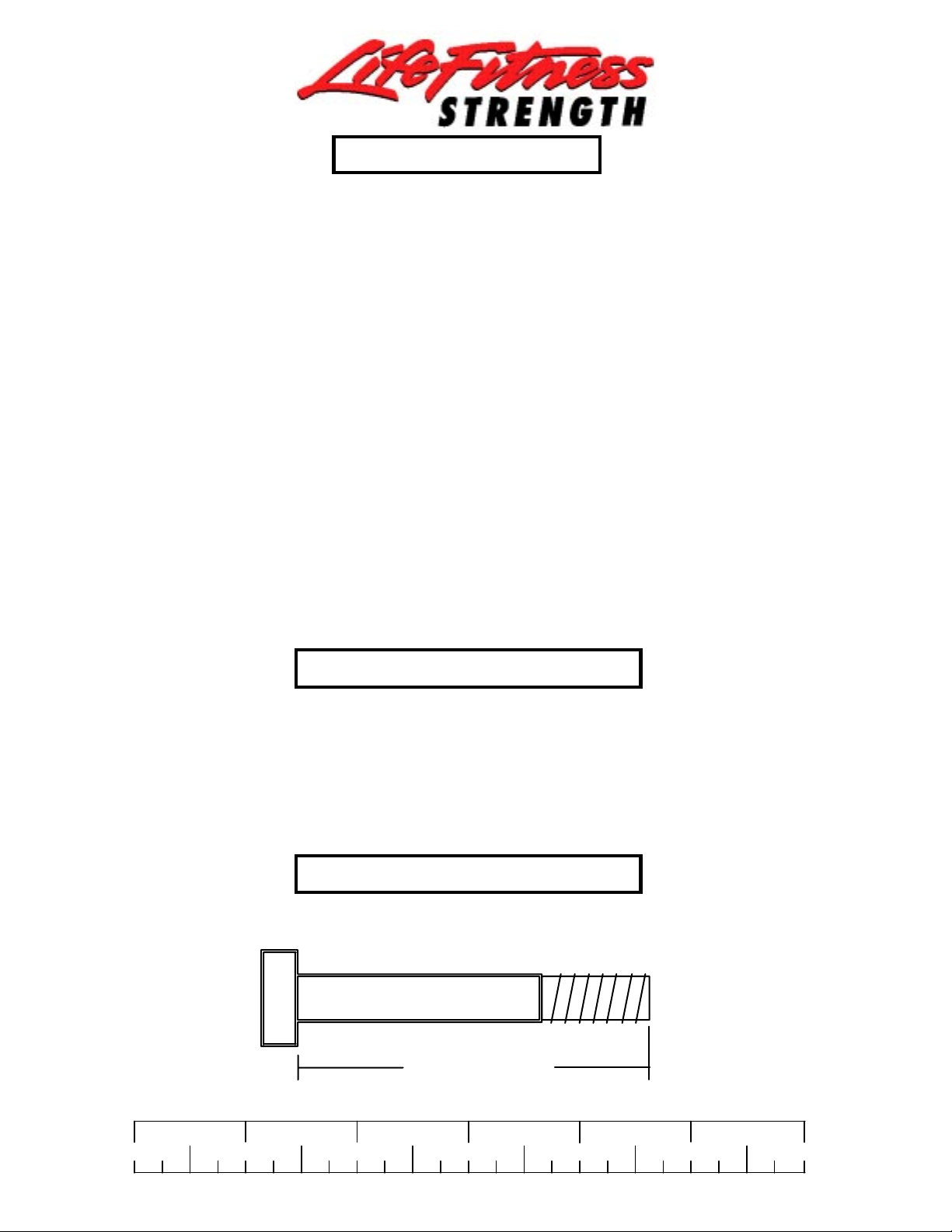
Bolt Length Ruler
NOTE: BOL T LENGTH IS MEASURED FROM THE UNDERSIDE OF THE HEAD OF THE BOLT.
BOLT LENGTH
BOL T LENGTH RULER:
1/2 1/2 1/2 1/2 1/2 1/2
0
1
2
345
2
6
Page 3

PARTS LIST
KEY
1
2
3
4
5
6
7
8
9
10
11
12
13
14
15
16
17
18
19
20
21
22
23
24
25
26
27
28
29
30
31
32
33
34
35
36
37
38
39
40
41
42
43
44
45
46
47
48
49
50
51
52
53
54
55
56
57
58
59
PART #
6617103
6779802
6625502
6624202
6624302
6622903
6623003
6623503
6624502
6622503
6620903
6691803
6692402
6623702
6662203
6662303
6628302
6275302
6523401
6765203
6765303
6769903
6768003
6767903
6769003
6769702
6769803
6772102
6768803
6768503
6769203
6965503
6872502
6771003
6770102
6871702
6768303
6770703
6772201
6772301
6764901
6773101
6962401
6773301
6954901
6773501
3108002
3116101
3202301
6284501
6389701
6619301
6714601
3116001
6594702
6651602
6868702
6122702
3118401
DESCRIPTION
REAR UPRIGHT
LEG BACK P AD ADJUST
LEG BACK P AD SUPPORT
BACK P AD ANGLE LEFT
BACK P AD ANGLE RIGHT
PEC ARM RIGHT
PEC ARM LEFT
PRESS ARM
CALF/LOW ROW
BEARING HOUSING
FLOA TING PULLEY STOP
SEA T SUPPOR T
P AD SUPPORT
WOLFF SLEEVE
LEG EXT HANDLE RIGHT
LEG EXT HANDLE LEFT
2 X 8” PLA TE
LA T BAR
72-3/8” GUIDE ROD
PRESS G .R. SUPPOR T
LEG G .R. SUPPORT
PEC G .R. SUPPOR T
LEG WT . STACK BASE
PRESS WT . ST ACK BASE
BASE
PULLEY BRACKET
CENTER PULLEY BRACKET
PEC CAM
FRONT UPRIGHT
TOP BOOM
REAR BASE LEG
LEG CURL/EXTENSION
P AD SLEEVE
LEG FRAME
SWIVEL PULLEY BRACKET
PRESS ARM ADJUST
PRESS FRAME
PRESS BASE
19-1/4” TUBE
21-1/2” TUBE
4 X 7” ROLLER P AD
LA T CABLE ASSEMBL Y
LEG CABLE ASSEMBL Y
PRESS CABLE ASSEMBL Y
AB CRUNCH CABLE ASSEMBLY
PEC DEC CABLE ASSEMBL Y
WEIGHT ST ACK CUSHION
4-1/2” PULLEY
PILLOW BLOCK BEARING
20 HOLE SELECTOR SHAFT
LOW ROW CHROME BAR
U-PIN
HEAD PLA TE
1-1/4” SQ. RUBBER BUMPER
FLOA TING PULLEY BRACKET
2 X 15-1/2” PLA TE
4-1/2 X 8” PLA TE
3/8 X 1/2” SPACER
4” VINYL CAP
QTY
1
1
1
1
1
1
1
1
1
1
1
1
1
1
1
1
1
1
6
1
1
1
1
1
1
1
1
2
1
1
1
1
2
1
1
1
1
1
1
1
8
1
1
1
1
1
8
24
2
3
1
1
3
3
1
2
1
2
1
60
61
62
63
64
65
66
67
68
69
70
71
72
73
74
75
76
77
78
79
80
81
82
83
84
85
86
87
88
89
90
91
92
93
94
95
96
97
98
99
100
101
102
103
104
105
106
107
108
109
110
111
112
113
114
115
116
118
PART #
6140701
6177001
6412001
6466901
6954703
6692601
6781601
6757701
3103801
6480301
6020601
3104901
6619501
3109602
6075906
6214401
6406401
6695001
3103302
3103304
3102501
3114502
3102802
3102807
3102502
3102801
3102804
3202401
3102901
3102933
3102922
3102915
3102906
3202101
3102910
3102918
3102917
3202107
3202105
6780101
6780001
6780301
6780201
6780401
6780601
6780501
6214501
6703801
6189501
6382301
6375801
6779703
6779503
6779601
3102909
3108404
6827001
6122704
2-1/2 X 5-1/2 NON-SKID STRIP
3/8 X 2-3/4” DIA. SPRING PIN
1/2 X 3-1/2” DIA. SPRING PIN
3/8” LOW HEIGHT LOCK NUT
1/2” LOW HEIGHT LOCK NUT
3/8 X 1” BTTN HD CAP SCREW
WEIGHT PLA TE LABELS (LBS.)
WEIGHT PLATE LABELS (1-25)
WEIGHT PLA TE BUSHING (10 CT)
3/8 X 3” COUNTERSUNK BOL T
KEY
3
DESCRIPTION
1 X 1” GLIDE
AB PULLEY PLA TE
3 X 2” END CAP
1/2 X 7-7/8” SPRING PIN
2-7/8 X 1” CABLE CLIP
5/16” SNAP LINK
3/8” FLANGE SP ACER
1/2” FLANGE BEARING
3/4” FLANGE BEARING
3/4” SLEEVE BEARING
1/2” P AL NUT
12 LINK CHAIN
WEIGHT ST ACK PIN
HINGE T AB
3/4” DIA. T APPED SHAFT
13/16” SHAFT COLLAR
1-5/16” SHAFT COLLAR
3/8” WASHER
3/8” LOCK WASHER
3/8” LOCK NUT
1/2” WASHER
1/2” LOCK NUT
3/8 X 1-1/4” BOLT
3/8 X 2” BOLT
3/8 X 2-3/4” BOLT
3/8 X 3-1/4” BOLT
3/8 X 4” BOLT
1/2 X 1-1/4” BOLT
1/2 X 3” BOLT
1/2 X 3-1/4” BOLT
1/2 X 4” BOLT
1/2 X 6-1/2” BOLT
1/2 X 7-1/2” BOLT
PEC ARM PAD
PRESS SEA T P AD
PRESS BACK P AD
LEG SEA T PAD
LEG BACK P AD
PEC SEA T P AD
PEC BACK P AD
WEIGHT PLA TE
AB CRUNCH STRAP
LEG SHROUD
PEC SHROUD
PRESS SHROUD
3/8 X 1” BOLT
2-7/8 X 2-1/4” CABLE CLIP
1/4” SPACER
QTY
5
4
6
1
2
2
1
12
4
24
4
6
2
1
1
3
4
1
6
8
67
5
41
3
21
24
8
4
15
14
16
16
4
2
7
8
10
2
1
2
1
1
1
1
1
1
60
1
1
12
1
1
1
1
12
2
8
4
Page 4
1/2 X 3-1/4” 95
23
25
61
85
24
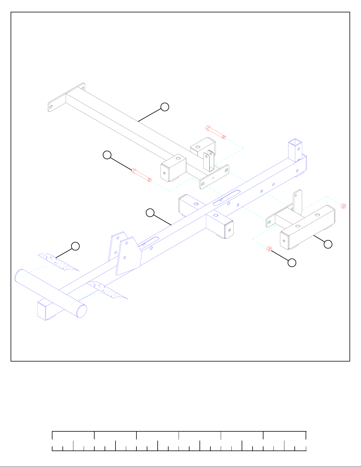
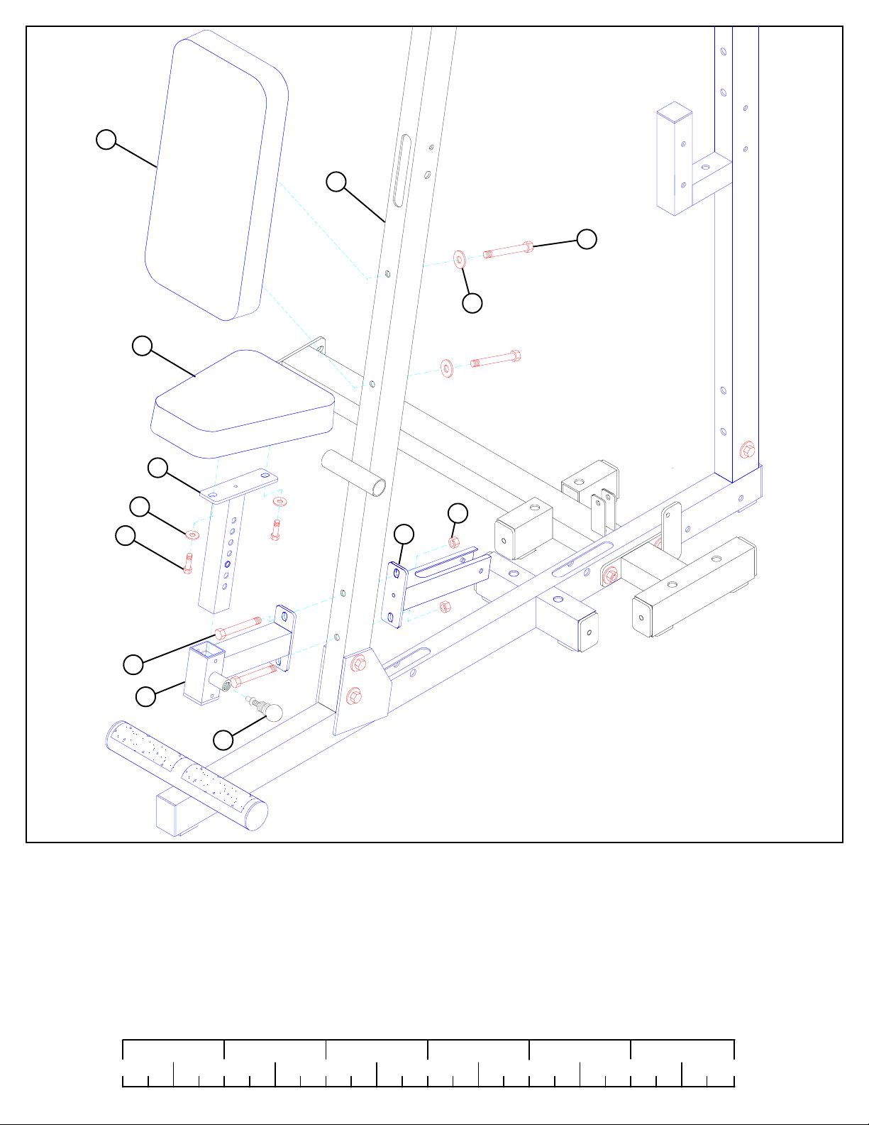
FIGURE 1
STEP 1:
• LOOSELY assemble the LEG WEIGHT STACK BASE (23) and the PRESS WEIGHT STACK BASE (24) to the BASE (25) using two
1/2 X 3-1/4” BOLTS (95) and two 1/2” LOCK NUTS (85) as shown in FIGURE 1.
• Apply two NON-SKID STRIPS (61) to the BASE (25) as shown in FIGURE 1.
1/2 1/2 1/2 1/2 1/2 1/2
0
1
2
345
4
6
Page 5
30
96 1/2 X 4””
84
85
85
95 1/2 X 3-1/4”
1
29
85
84
94 1/2 X 3”
85
25
95 1/2 X 3-1/4”
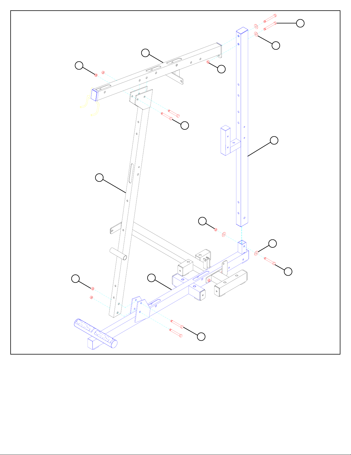
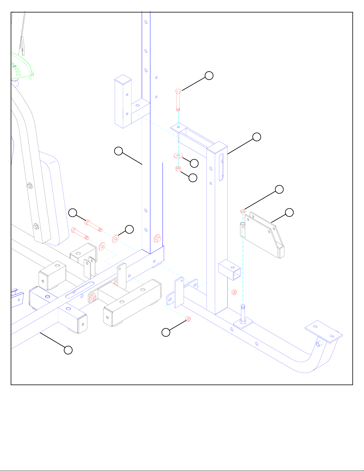
FIGURE 2
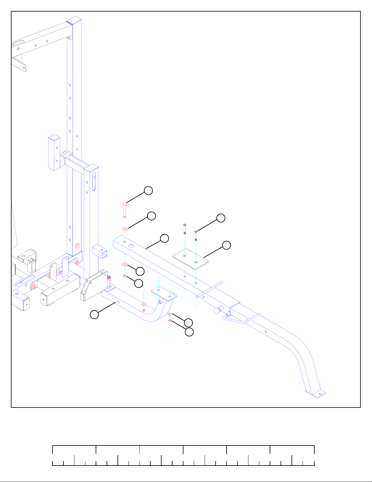
STEP 2:
• LOOSELY assemble the FRONT UPRIGHT (29) to the BASE (25) using two 1/2 X 3-1/4” BOLTS (95) and two 1/2” LOCK NUTS (85)
as shown in FIGURE 2.
• LOOSELY assemble the REAR UPRIGHT (1) to the BASE (25) using one 1/2 X 3” BOLT (94), two 1/2” WASHERS (84), and one 1/2”
LOCK NUT (85) as shown in FIGURE 2.
• LOOSELY assemble the TOP BOOM (30) to the REAR UPRIGHT (1) using two 1/2 X 4” BOLTS (96), two 1/2” WASHERS (84), and
one 1/2” LOCK NUT (85) as shown in FIGURE 2.
• LOOSELY assemble the TOP BOOM (30) to the FRONT UPRIGHT (29) using two 1/2 X 3-1/4” BOLTS (95) and two 1/2” LOCK NUTS
(85) as shown in FIGURE 2.
TIGTEN ALL LOOSE FRAME CONNECTIONS MADE TO THIS POINT!
5
Page 6
105
29
92 3/8 X 4”
80
104
13
80
3/8 X 1-1/4” 88
1/2 X 4” 96
12
62
1/2”
LOW
HEIGHT
11
86
FIGURE 3
STEP 3:
• SECURELY assemble the FLOATING PULLEY STOP (11) and the SEAT SUPPORT (12) to the FRONT UPRIGHT (29) using two 1/2
X 4” BOLTS (96) and two 1/2” LOW HEIGHT LOCK NUTS (86) as shown in FIGURE 3.
• SECURELY assemble one 3/8 X 2-3/4” SPRING PIN (62) to the SEAT SUPPORT (12) as shown in FIGURE 3.
• SECURELY assemble one PEC SEAT PAD (104) to the PAD SUPPORT (13) using two 3/8 X 1-1/4” BOLTS (88) and two 3/8” WASHERS
(80) as shown in FIGURE 3.
• CAREFULLY insert the PAD SUPPORT (13) into the SEAT SUPPORT (12) and engage the SPRING PIN into one of the holes.
• SECURELY assemble one PEC BACK PAD (105) to the FRONT UPRIGHT (29) using two 3/8 X 4” BOLTS (92) and two 3/8” WASHERS
(80) as shown.
1/2 1/2 1/2 1/2 1/2 1/2
0
1
2
345
6
6
Page 7
1/2 X 4” 96
60
10
79
72
28
7
71
71
84
85
6
62
41
40
99
29
27
86
1/2”
LOW HEIGHT
80
3/8 X 3-1/4” 91
FIGURE 4
STEP 4:
• SECURELY assemble the BEARING HOUSING (10) and the CENTER PULLEY BRACKET (27) to the FRONT UPRIGHT (29) using two
1/2 X 4” BOLTS (96) and two 1/2” LOW HEIGHT LOCK NUTS (86).
• Assemble the RIGHT PEC ARM (6) and one PEC CAM (28) to the BEARING HOUSING (10) using one 3/4” SLEEVE BEARING (72), two
3/4” FLANGE BEARINGS (71), one 1/2” WASHER (84), and one 1/2” LOCK NUT (85) as shown in FIGURE 4. (NOTE: SECURELY
tighten, then back nut off 1/4 turn to allow the PEC ARM to rotate freely.)
• Assemble the LEFT PEC ARM (7) and one PEC CAM (28) to the BEARING HOUSING (10) using one 3/4” SLEEVE BEARING (72), two
3/4” FLANGE BEARINGS (71), one 1/2” WASHER (84), and one 1/2” LOCK NUT (85) as shown in FIGURE 4. (NOTE: SECURELY
tighten, then back nut off 1/4 turn to allow the PEC ARM to rotate freely.)
• SECURELY assemble a 3/8 X 2-3/4” SPRING PIN (62) to the to the RIGHT & LEFT PEC ARM (6 & 7). See FIGURE 4.
• Apply two 1” X 1” GLIDES (60) to the BEARING HOUSING (10) where the PEC CAMS (28) come in contact with the BEARING HOUSING
(10) as shown.
• SECURELY assemble one PEC ARM PAD (99) to both the RIGHT & LEFT PEC ARMS (6 & 7) using four 3/8 X 3-1/4” BOLTS (91) and
four 3/8” WASHERS (80). See FIGURE 4.
• SECURELY assemble two 4 X 7” ROLLER PADS (41) to the FRONT UPRIGHT (29) using one 21-1/2” TUBE (40) and two 1-5/16” SHAFT
COLLARS (79). SECURELY tighten set screws on SHAFT COLLARS (79). See FIGURE 4.
7
Page 8
14
73
62
59
37
52
FIGURE 5
STEP 5:
• SECURELY assemble one 3/8 X 2-3/4” SPRING PIN (62) to the WOLFF SLEEVE (14) as shown in FIGURE 5.
• Assemble one U-PIN (52) to the WOLFF SLEEVE (14) using one 1/2” PAL NUT (73).
• Slide one 4” VINYL SLEEVE (59) onto the U-PIN (52) as shown in FIGURE 5.
• CAREFULLY slide the WOLFF SLEEVE (14) onto the PRESS FRAME (37) until the SPRING PIN engages in one of the holes.
1/2 1/2 1/2 1/2 1/2 1/2
0
1
2
345
8
6
Page 9
1
94 1/2 X 3”
38
84
85
86 1/2” LOW HEIGHT
FIGURE 6
94 1/2 X 3”
25
35
84
85
STEP 6:
• SECURELY assemble the PRESS BASE (38) to the BASE (25) using two 1/2 X 3” BOLTS (94), two 1/2” WASHERS (84), and two 1/2”
LOCK NUTS (85), and to the REAR UPRIGHT (1) using one 1/2 X 3” BOLT (94), one 1/2” WASHER (84), and one 1/2” LOCK NUT
(85) as shown in FIGURE 6.
• Assemble the SWIVEL PULLEY BRACKET (35) to the PRESS BASE (38) using one 1/2” LOW HEIGHT LOCK NUT (86) as shown in
FIGURE 6. (NOTE: Securely tighten, then back nut off 1/4 turn to allow the SWIVEL PULLEY BRACKET to rotate freely.)
9
Page 10
94 1/2 X 3”
38
85
84
84
115 3/8 X 3” COUNTER SUNK
37
57
80
82
FIGURE 7
STEP 7:
• SECUREL Y assemble the PRESS FRAME (37) to the PRESS BASE (38) using one 1/2” X 3” BOL T (94), two 3/8 X 3” COUNTERSUNK BOL TS (115),
one 4-1/2” X 8” PLA TE (57), two 1/2” W ASHERS (84), two 3/8” W ASHERS (80), one 1/2” LOCK NUT (85), and two 3/8” LOCK NUTS (82). (NOTE:
Make sure 3/8” countersunk bolts are facing down.) See FIGURE 7.
1/2 1/2 1/2 1/2 1/2 1/2
0
1
2
345
10
6
Page 11
80
101
3/8 X 1-1/4” 88
54
1/2 X 1-1/4” 93
37
116
4
38
14
76
80
3/8 X 1-1/4” 88
84
85
5
HEIGHT
86
1/2”
LOW
100
97 1/2 X 6-1/2”
FIGURE 8
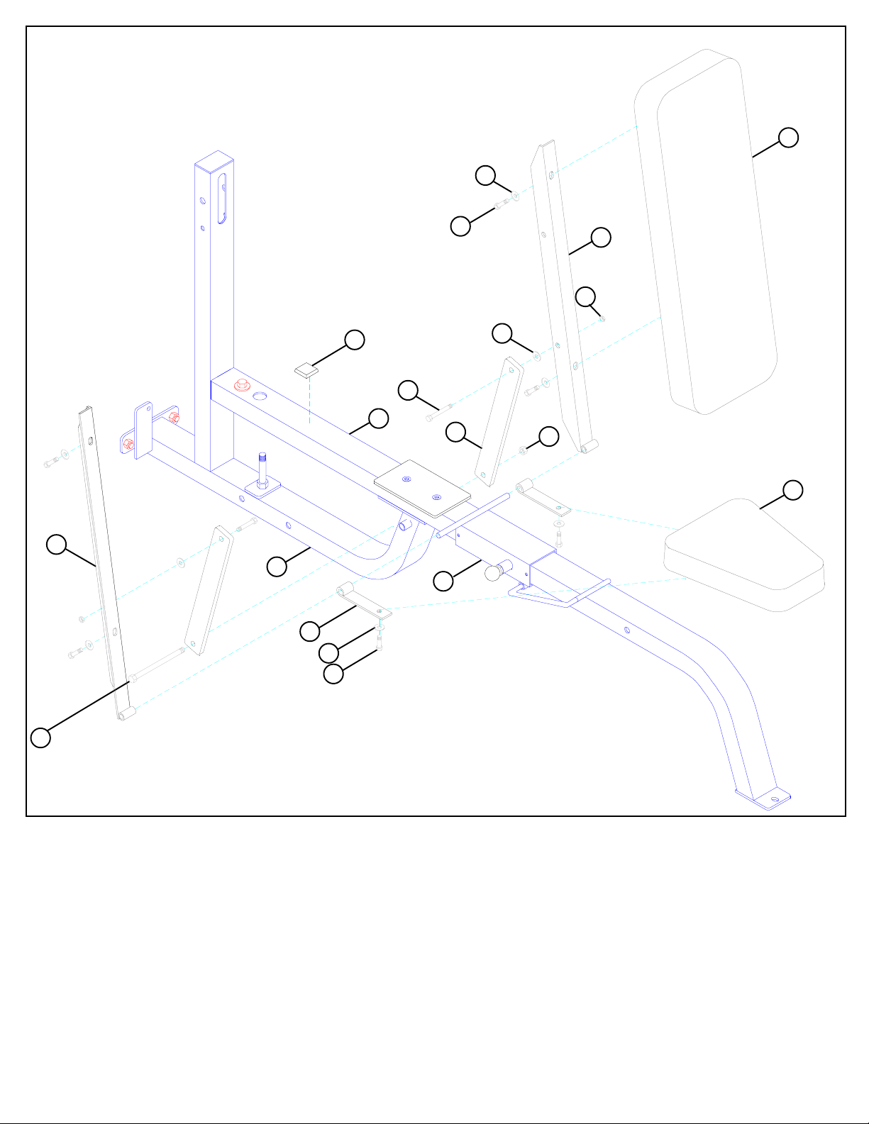
STEP 8:
• Slide two HINGE TABS (76) onto the WOLFF SLEEVE (14) and SECURELY attach PRESS SEAT PAD (100) using two 3/8 X 1-1/4”
BOLTS (88) and two 3/8” WASHERS (80). (NOTE: The “hinge” part of the HINGE TAB (76) should face upward as shown in
FIGURE 8.)
• Slide the RIGHT BACK PAD ANGLE (5) and LEFT BACK PAD ANGLE (4) onto the WOLFF SLEEVE (14) and attach the PRESS
BACK PAD (101) using four 3/8 X 1-1/4” BOLTS (88) and four 3/8” WASHERS (80). See FIGURE 8.
• SECURE two 2 X 15-1/2” PLATES (56) to the RIGHT BACK PAD ANGLE (5) and the LEFT BACK PAD ANGLE (4) using two 1/2 X 11/4” BOLTS (93), two 1/2” WASHERS (84) and two 1/2” LOW HEIGHT LOCK NUTS (86). (NOTE: SECURE lock nuts, then back off
1/4 turn.)
• SECURE the 2 X 15-1/2” PLATES (56) to the bushing in the PRESS BASE (38) using one 1/2 X 6-1/2” BOLT (97) and one 1/2” LOCK NUT
(85) as shown in FIGURE 8.
• Apply one 1-1/4” RUBBER BUMPER (54) to the PRESS FRAME (37) where the back of the pad comes in contact with the frame.
11
Page 12

1
82
36
49
80
91 3/8 X 3-1/4”
85
84
38
9
96 1/2 X 4”
61
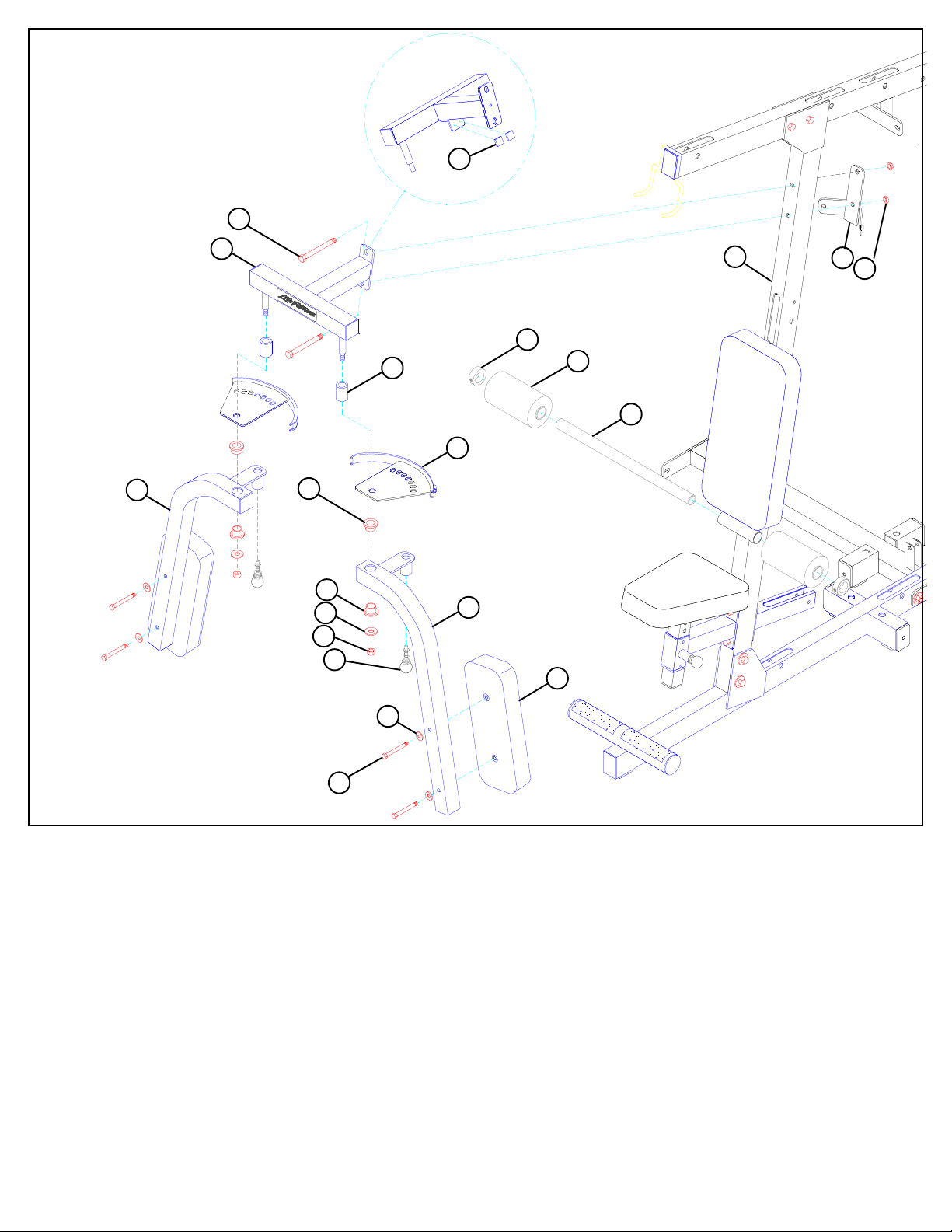
FIGURE 9
STEP 9:
• LOOSELY assemble the PRESS ARM ADJUST (36) to the REAR UPRIGHT (1) using two 1” PILLOW BLOCK BEARINGS (49), four
3/8 X 3-1/4” BOLTS (91), four 3/8” WASHERS (80), and four 3/8” LOCK NUTS (82). (NOTE: Assemble PILLOW BLOCKS (49) so the
set screws are on the outside, this will allow more adjustment.) See FIGURE 9.
• Center PRESS ARM ADJUST (36) to line up with the post on the PRESS BASE (38) and securely tighten set screws on the PILLOW BLOCK
BEARINGS (49). See FIGURE 9.
• Adjust the PILLOW BLOCK BEARINGS (49) until the PRESS ARM ADJUST (36) is level, then SECURELY tighten bolts.
• SECURELY assemble CALF/LOW ROW (9) to the PRESS BASE (38) using two 1/2 X 4” BOLTS (96), two 1/2” WASHERS (84), and two
1/2” LOCK NUTS (85) as shown in FIGURE 9.
• Apply two NON-SKID STRIPS (61) to the CALF/LOW ROW (9) as shown in FIGURE 9.
1/2 1/2 1/2 1/2 1/2 1/2
0
1
2
345
12
6
Page 13

90 3/8 X 2-3/4”
36
82
70
63
98 1/2 X 7-1/2”
86 1/2” LOW HEIGHT
84
8
FIGURE 10
STEP 10:
• SECURELY assemble one 1/2 X 3-1/2” SPRING PIN (63) to the PRESS ARM (8) as shown in FIGURE 10.
• SECURELY assemble the PRESS ARM (8) to the PRESS ARM ADJUST (36) using one 1/2 X 7-1/2” BOLT (98), two 1/2” WASHERS (84),
two 1/2” FLANGE BEARINGS (70), and one 1/2” LOW HEIGHT LOCK NUT (86). (NOTE: SECURELY tighten, then back nut off 1/4
to allow the PRESS ARM to rotate freely.)
• SECURELY assemble four 3/8 X 2-3/4” BOL TS (90) and four 3/8” LOCK NUTS (82) to the PRESS ARM ADJUST (36) as sjown in FIGURE 10.
13
Page 14

34
85
86
31
94 1/2 X 3”
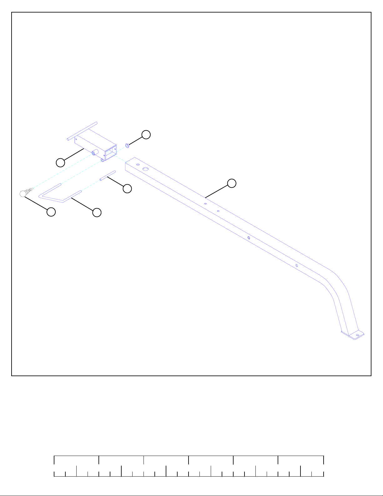
FIGURE 11
STEP 11:
• SECURELY assemble the REAR BASE LEG (31) to the LEG FRAME (34) using two 1/2 X 3” BOLTS (94), two 1/2” WASHERS (84), and
two 1/2” LOCK NUTS (85) as shown in FIGURE 11.
76
FIGURE 12
82
80
16
15
34
76
95 3/8 X 3-1/4”
STEP 12:
• SECURELY assemble the LEFT & RIGHT LEG EXTENSION HANDLES (16 & 15) to the LEG FRAME (34) using two 3/8 X 3-1/4”
BOLTS (91), four 3/8” WASHERS (80), and two 3/8” LOCK NUTS (82). See FIGURE 12.
• Slide two HINGE TABS (76) onto the LEG FRAME (34) as shown in FIGURE 12. (NOTE: The “hinge” part of the HINGE TAB should
face downward.)
1/2 1/2 1/2 1/2 1/2 1/2
0
1
2
345
14
6
Page 15

STEP 13:
88 3/8 X 1-1/4”
• SECURELY assemble one 2 X 8” PLATE (17) to the LEG SEAT
PAD (102) using two 3/8 X 1-1/4” BOLTS (88) and two 3/8”
WASHERS (80). See FIGURE 13.
• Apply one 1-1/4” RUBBER BUMPER (54) to the 2 X 8” PLATE
(17) as shown in FIGURE 13.
FIGURE 13
102
54
80
17
102
FIGURE 14
34
66
76
80
88 3/8 X 1-1/4”
STEP 14:
• SECURELY assemble the LEG SEAT PAD (102) to the HINGE TABS (76) using two 3/8 X 1-1/4” BOLTS (88) and two 3/8” WASHERS
(80). See FIGURE 14.
• SECURELY assemble one 1/2 X 7-7/8” SPRING PIN (66) to the LEG FRAME (34) as shown in FIGURE 14.
15
Page 16

60
3
1/2 X 6-1/2” 97
2
2
3/8 X 1” BUTTON HEAD 87
32
FIGURE 15
3/8” BLACK
70
81 LOCKWASHER
85
71
77
54
NOTE: TIGHTEN BOTH AT
THE SAME TIME!
34
STEP 15:
• SECURELY assemble one 1 X 1” GLIDE (60) to the angle on the BACK PAD ADJUST (2) as shown in FIGURE 15.
• Assemble LEG BACK PAD ADJUST (2) and LEG BACK PAD SUPPORT (3) to the LEG FRAME (34) using one 1/2 X 6-1/2” BOLT (97),
two 1/2” FLANGE BEARINGS (70), one 1/2” LOCK NUT (85) as shown in FIGURE 15. (NOTE: Securely tighten, then back nut off 1/4
turn to allow the two parts to rotate freely.)
• SECURELY assemble the LEG CURL/EXTENSION (32) to the LEG FRAME (34) using two 3/4” FLANGE BEARINGS (71), one 3/4”
TAPPED SHAFT (77), two black 3/8” LOCK WASHERS (81), and two 3/8 X 1” BLACK BUTTON HEAD CAP SCREWS (87). (NOTE:
Both CAP SCREWS must be tightened at the same time using two allen wrenches.)
• SECURELY assemble one 1-1/4” RUBBER BUMPER (54) to the contact point on the LEG FRAME (34) as shown in FIGURE 15.
1/2 1/2 1/2 1/2 1/2 1/2
0
1
2
345
16
6
Page 17

79
3/8 X 3-1/4” 91
80
3
41
103
39
2
34
FIGURE 16
STEP 16:
• SECURELY assemble the LEG BACK PAD (103) to the LEG BACK PAD ADJUST (2) and the LEG BACK PAD SUPPORT (3) using
four 3/8 X 3-1/4” BOLTS (91) and four 3/8” WASHERS (80). See FIGURE 16.
• SECURELY assemble two 4 X 7” ROLLER PADS (41) to the LEG FRAME (34) using one 19-1/4” TUBE (39) and two 1-5/16” SHAFT
COLLARS (79). SECURELY tighten set screws on SHAFT COLLARS (79). See FIGURE 16.
17
Page 18

82
32
84
85
87 3/8 X 1-1/4”
BUTTON
HEAD
34
23
1/2 X 4” 96
65
33
62
41
79
FIGURE 17
STEP 17:
• SECURELY assemble two 3/8 X 2-3/4” SPRING PINS (62) to the PAD SLEEVES (33) as shown in FIGURE 17.
• Assemble four ROLLER PADS (41) to the PAD SLEEVES (33) using four 1-5/16” SHAFT COLLARS (79). SECURELY tighten set
screws on SHAFT COLLARS (79). See FIGURE 16.
• Slide PAD SLEEVES (33) over LEG CURL/EXTENSION (32) until the spring pin pops into the holes. (NOTE: PAD SLEEVES should be facing
as shown in FIGURE 17.)
• SECURELY assemble two 3/8 X 1” BUTTON HEAD CAP SCREWS (87) and two 3/8” LOCK NUTS (82) to the last holes in the LEG
CURL/EXTENSION (32) as shown in FIGURE 17.
• Insert two 3 X 2” END CAPS (65) into the ends of the LEG CURL/EXTENSION (32) as shown in FIGURE 17.
• SECURELY assemble LEG FRAME (34) to the LEG WEIGHT STACK BASE (23) using two 1/2 X 4” BOLTS (96), two 1/2” WASHERS
(84), and two 1/2” LOCK NUTS (85). See FIGURE 17.
STEP 18:
• Snap two WEIGHT PLATE BUSHINGS (109) into the top side of all
sixty WEIGHT PLATES (106) as shown in FIGURE 18.
106
109
FIGURE 18
1/2 1/2 1/2 1/2 1/2 1/2
0
1
2
345
18
6
Page 19

3/8” LOCK
WASHER 81
3/8 X 1-1/4” 88
78
19
53
FIGURE 19
106
47
50
TWO PER SIDE
ON THIS STACK ONLY!
108
107
TWO
PER
SIDE!
23
24
25
STEP 19:
• Insert the two GUIDE RODS (19) into the BASE (25) as shown in FIGURE 19. Lubricate the GUIDE RODS (19) with a slicon or teflon
spray that is available at most hardware stores.
• Slide two WEIGHT STACK CUSHIONS (47) down over the GUIDE RODS (19). See FIGURE 19.
• Using EXTREME CARE slide twenty WEIGHT PLATES (106) down over the GUIDE RODS (19) with the the key-hole facing as
shown in FIGURE 19.
• SECURELY assemble the WEIGHT STACK SHAFT (50) to the HEAD PLATE (53) using one 3/8 X 1-1/4” BOLT (88) and one 3/8”
BLACK LOCK WASHER (81). (Note: The bolt hole in the HEAD PLATE (53) should be on top.)
• Carefully Slide the HEAD PLATE ASSEMBLY down over the GUIDE RODS (19) onto the weight stack as shown.
• Apply one set of WEIGHT STACK LABELS - LBS. OR NUMBERED 1-20 (107) (108) to each WEIGHT PLATE (106). See FIGURE 19.
• Slide two 13/16” SHAFT COLLARS (78) over the GUIDE RODS (19) as shown in FIGURE 19.
• REPEAT the above steps to assemble the weight stacks on the PRESS WEIGHT STACK BASE (24) and the LEG WEIGHT STACK
BASE (23). (NOTE: Use four WEIGHT STACK CUSHIONS (47) (two per guide rod!) on the LEG WEIGHT STACK BASE (23)
as shown in FIGURE 19.)
19
Page 20

85
21
20
30
19
95 1/2 X 3-1/4”
FIGURE 20
STEP 20:
• Slide the PRESS GUIDE ROD SUPPORT (20) and LEG GUIDE ROD SUPPORT (21) over their respective GUIDE RODS (19) and
SECURELY assemble them to the TOP BOOM (30) using two 1/2 X 3-1/4” BOLTS (91) and two 1/2” LOCK NUTS (85) as shown in
FIGURE 20.
21
20
80
3/8 X 2-3/4” 90
30
22
78
19
83 3/8” LOW HEIGHT
FIGURE 21
STEP 21:
• Slide the PEC GUIDE ROD SUPPORT (22) onto the GUIDE RODS (19) and SECURELY assemble the PEC GUIDE ROD SUPPORT (22)
to TOP BOOM (30) using two 3/8 X 2-3/4” BOLTS (90), four 3/8” WASHERS (80), and two 3/8” LOW HEIGHT LOCK NUTS (83). See
FIGURE 21.
• Slide the 13/16” SHAFT COLLARS (78) to the top of the GUIDE ROD SUPPORTS (20,21,22) and SECURELY tighten the SHAFT
COLLARS set screws. See FIGURE 21.
1/2 1/2 1/2 1/2 1/2 1/2
0
1
2
345
20
6
Page 21

46
44
45
21
42
43
Page 22

82
48
30
69
116
LAT CABLE 42
90
3/8 X 2-3/4”
FIGURE 22
STEP 22:
• Route the threaded end of the LAT CABLE (42) through the TOP BOOM (30) as shown in FIGURE 22.
• SECUREL Y assemble two 4-1/2” PULLEYS (48) into the slots of the TOP BOOM (30) using two 3/8 X 2-3/4” BOLTS (90), four 3/8” FLANGE
SP ACERS (69), two 2-7/8” X 2-1/4” CABLE CLIPS (116) and two 3/8” LOCK NUTS (82). (NOTE: Loop the cable around each pulley prior to
inserting it in the the slot.)
55
48
67
82
STEP 23:
• SECUREL Y assemble one 4-1/2” PULLEY (48) to the FLOA TING PULLEY BRACKET (55)
using one 3/8 X 2” BOLT (89), two 2-7/8 X 1” CABLE CLIPS (67) and one 3/8” LOCK
NUT (82) as shown in FIGURE 23.
• Apply two 1 X 1” GLIDES (60) to the FLOATING PULLEY BRACKET (55) as shown.
60
3/8 X 2” 89
FIGURE 23
STEP 24:
• SECURELY assemble one 4-1/2” PULLEY (48) to the FLOATING
PULLEY STOP (10) using one 3/8 X 2-3/4” BOL T (90), one 2-7/8” X
2-1/4” CABLE CLIP (116), two 3/8” FLANGE SPACERS (69), and
one 3/8” LOCK NUT (82) as shown in FIGURE 24.
1/2 1/2 1/2 1/2 1/2 1/2
0
1
2
FIGURE 24
48
82
69
11
345
22
116
3/8 X 2-3/4” 90
6
Page 23

42
LAT
CABLE
55
11
48
90 3/8 X 2-3/4”
FIGURE 25
82
69
25
STEP 25:
• Route the LAT CABLE (42) around the pulley in FLOA TING PULLEY ST OP (1 1) and the FLOA TING PULLEY BRACKET (55) as shown in
FIGURE 25. (NOTE: The CABLE CLIPS may need to be loosened.)
• SECURELY assemble two 4-1/2” PULLEYS (48) into the slots of the BASE (25) using two 3/8 X 2-3/4” BOLTS (90), four 3/8” FLANGE
SPACERS (69), and two 3/8” LOCK NUTS (82). (NOTE: Loop the cable around each pulley prior to inserting it in the the slot.)
48
LAT CABLE 42
82
69
116
30
90 3/8 X 2-3/4”
FIGURE 26
STEP 26:
• Route the threaded end of the LAT CABLE (42) through the TOP BOOM (30) and down through the PEC GUIDE ROD SUPPORT (22) as
shown in FIGURE 26.
• SECUREL Y assemble one 4-1/2” PULLEY (48) into the rear slot of the TOP BOOM (30) using one 3/8 X 2-3/4” BOL T (90), two 3/8” FLANGE
SP ACERS (69), one 2-7/8” X 2-1/4” CABLE CLIP (1 16) and one 3/8” LOCK NUT (82). (NOTE: Loop the cable around the pulley prior to inserting
it in the the slot.)
23
Page 24

CABLE
50
53
42
LAT
FIGURE 27
STEP 27:
• Screw the threaded end of the LAT CABLE (42) approximately 1” into the end of the SELECTOR SHAFT (50) of the HEAD PLATE (53) as
shown in FIGURE 27.
STEP 28:
• LOOSELY assemble two 4-1/2” PULLEYS (48)
to the CENTER PULLEY BRACKET (27) using
two 3/8 X 2” BOLTS (89), two 2-7/8” CABLE
CLIPS (67), two 3/8” WASHERS (80), and two
3/8” LOCK NUTS (82). See FIGURE 28.
82
80
3/8 X 2” 89
27
67
48
FIGURE 28
1/2 1/2 1/2 1/2 1/2 1/2
0
1
2
345
24
6
Page 25

3/8 X 2” 89
48
82
46 PEC CABLE
67
FIGURE 29
26
STEP 29:
• Assemble one 4-1/2” PULLEY (48) around the PEC DEC CABLE (46) and to the PULLEY BRACKET (26) using one 3/8 X 2” BOLT (89),
two 2-7/8 X 1” CABLE CLIPS (67) and one 3/8” LOCKNUT (82) as shown in FIGURE 29.
STEP 30:
• Slide the ends of the PEC DEC CABLE
(46) into the bushings on the PEC CAMS
(28) as shown on FIGURE 30.
• Lay the PEC DEC CABLE (46) over the
pulleys and under the cable retaining clips
in the CENTER PULLEY BRACKET (27)
as shown in FIGURE 30. (NOTE: Securely
tighten the pulley connections in the
CENTER PULLEY BRACKET (27).
The cable retaining clips should be at approximately a 45° angle.)
27
46
46
PEC
CABLE
FIGURE 30
28
25
Page 26

SEE DETAIL 31
45 AB CABLE
80
69
95 3/8 X 3-1/4”
117
48
118
FIGURE 31
DETAIL 31
STEP 31:
• Securely assemble the ball end of the AB CABLE (45) and one 4-1/2” PULLEY (48) to the FRONT UPRIGHT (29) using two AB PULLEY
PLATES (117), two 3/8 X 3-1/4” BOLTS (91), four 1/4” SPACERS (118), two 3/8” FLANGE SPACERS (69), two 3/8” WASHERS (80) and
four 3/8” LOCKNUTS (82) . (NOTE: The AB CABLE (45) should be routed underneath the retaining bolt as shown in DETAIL 3.)
26
55
STEP 32:
• Route the AB CABLE (45) around the FLOATING PULLEY
BRACKET (55) using one 4-1/2” PULLEY (48), one 3/8 X 2”
BOL T (89), two 2-7/8 X 1” CABLE CLIPS (67), two 3/8” LOCK
NUTS (82). See FIGURE 32.
• Screw the threaded end of AB CABLE (45) approximately 1” into
the end of the PULLEY BRACKET (26) and tighten jam nut securely as shown in FIGURE 32.
IMPORTANT! Make sure the cables are running
in the grooves of all pulleys.
82
AB CABLE 45
67
3/8 X 2” 89
FIGURE 32
1/2 1/2 1/2 1/2 1/2 1/2
0
1
2
345
26
6
Page 27

44
37
48
44 PRESS CABLE
82
80
35
89 3/8 X 2”
FIGURE 33
STEP 33:
• SECURE the ball end of the PRESS CABLE (44) and two 4-1/2” PULLEYS (48) to the SWIVEL PULLEY BRACKET (35) using two 3/8
X 2” BOLTS (89), four 3/8” WASHERS (80), and two 3/8” LOCK NUTS (82) as shown in FIGURE 33. (NOTE: Loop the cable around
the pulleys prior to inserting it into the SWIVEL PULLEY BRACKET.)
• Route the threaded end of the PRESS CABLE (44) through the large hole in the PRESS FRAME (37) as shown in FIGURE 33.
27
Page 28

90 3/8 X 2-3/4”
92 3/8 X 4”
92 3/8 X 4”
36
38
48
58
69
FIGURE 34
82
116
69
80
44
82
STEP 34:
• Route the threaded end of the PRESS
CABLE (44) around one 4-1/2” PULLEY
(48) and SECURELY assemble the pulley
to the front slot of the PRESS ARM ADJUST (36) using one 3/8 X 2-3/4” BOLT
(90), two 3/8” FLANGE SPACERS (69),
and one 3/8” LOCK NUT (82) as shown in
FIGURE 34. (NOTE: Loop the cable over
the pulley prior to inserting it into the
slot.)
• Route PRESS CABLE (44) through the slot in
the PRESS BASE (38) then SECURELY as-
semble one 4-1/2” PULLEY (48) to the
PRESS BASE (38) using two 3/8 X 4”
BOLTS (92), two 2-7/8 X 2-1/4” CABLE
CLIPS (116), two 3/8” FLANGE SPACERS
(69), two 3/8 X 1/2” SPACERS (58), two 3/
8” WASHERS (80), and two 3/8” LOCK
NUTS (82) as shown in FIGURE 34.
(NOTE:Make sure the cable is routed between the pulley and the CABLE RETAINING BOLT.)
• Route the PRESS CABLE (44) around one
4-1/2” PULLEY (48) and SECURELY assemble the pulley to the rear slot of the
PRESS ARM ADJUST (36) using one 3/8
X 2-3/4” BOLT (90), two 3/8” FLANGE
SPACERS (69), and one 3/8” LOCK NUT
(82) as shown in FIGURE 34. (NOTE:
Loop the cable over the pulley prior to
inserting it into the slot.)
STEP 35:
• SECURE the PRESS CABLE (44) and two 4-1/2”
PULLEYS (48) to the vertical flats on the PRESS BASE
(38) and on the PRESS WEIGHT STACK BASE (24)
using two 3/8 X 2” BOLTS (89), two 2-7/8” CABLE
CLIPS (67) two 3/8” WASHERS (80), and two 3/8”
LOCK NUTS (82) as shown in FIGURE 35. (NOTE:
The PRESS CABLE (44) should be routed
underneath the short leg of the CABLE CLIP. Also,
the CABLE CLIPS should be positioned straight
down to function properly.)
1/2 1/2 1/2 1/2 1/2 1/2
0
1
2
89 3/8 X 2”
24
44 PRESS
CABLE
80
48
67
FIGURE 35
345
28
82
38
6
Page 29

FIGURE 36
3/8 X 2-3/4” 90
48
69
82
20
116
44 PRESS CABLE
STEP 36:
• SECURE the PRESS CABLE (44) and one 4-1/2” PULLEY (48) to the PRESS GUIDE ROD SUPPORT (20) using one 3/8 X 2-3/4”
BOLT (90), two 3/8” FLANGE SPACERS (69), one 2-7/8 X 2-1/4” CABLE CLIP (116) and one 3/8” LOCK NUT (82) as shown in
FIGURE 36. (NOTE: Loop the cable around the pulleys prior to inserting it into the PRESS GUIDE ROD SUPPORT.)
PRESS 44
CABLE
50
53
STEP 37:
• Screw the threaded end of the PRESS CABLE (44) approximately 1” into the end of the SELECTOR SHAFT (50) of the HEAD PLATE (53)
as shown in FIGURE 37.
29
Page 30

89
LEG CABLE 43
32
DO NOT OVERTIGHTEN!
83
LOW
HEIGHT
FIGURE 38
STEP 38:
• SECURE the swivel on the LEG CABLE (43) to the tab on the LEG EXT/CURL (32) using one 3/8 X 2” BOLT (89) and one 3/8” LOW
HEIGHT LOCK NUT (83) as shown in FIGURE 38. (NOTE: Do not overtighten! Swivel clevis should rotate freely.)
1/2 1/2 1/2 1/2 1/2 1/2
0
1
2
345
30
6
Page 31

82
48
34
80
43 LEG CABLE
80
3/8 X 2” 89
67
FIGURE 39
STEP 39:
• Route the LEG CABLE (43) through the vertical and horizontal brackets on the LEG FRAME (34) as shown in FIGURE 39.
• SECURELY assemble one 4-1/2” PULLEY (48) to the vertical bracket on the LEG FRAME (34) using one 3/8 X 2” BOLT (89), two
3/8” WASHERS (80), and one 3/8” LOCK NUT (82) as shown in FIGURE 39.
• SECURELY assemble one 3/8 X 2” BOL T (89), two 3/8” WASHERS (80), and one 3/8” LOCK NUT (82) to the vertical bracket as shown in
FIGURE 39. (Make sure CABLE is running over 3/8 X 2” RET AINING BOL T .)
• SECURELY assemble one 4-1/2” PULLEY (48) to the horizontal bracket on the LEG FRAME (34) using one 3/8 X 2” BOLT (89), one
3/8” WASHER (80), one 2-7/8” CABLE CLIP (67), and one 3/8” LOCK NUT (82) as shown in FIGURE 39. (NOTE: Before tightening,
make sure CABLE CLIP (67) is positioned as shown in FIGURE 39.)
IMPORTANT! Make sure the cables are running
in the grooves of all pulleys.
31
Page 32

48
43 LEG
CABLE
23
3/8 X 2” 89
80
67
82
FIGURE 40
STEP 40:
• Route the threaded end of the LEG CABLE (43) under the leg weight stack and throught the vetical bracket on the LEG WEIGHT
STACK BASE (23) as shown in FIGURE 40.
• Assemble one 4-1/2” PULLEY to the vertical bracket on the WEIGHT STACK BASE (23) using one 3/8 X 2” BOLT (89),one 2-7/8 X 1”
CABLE CLIP (67), two 3/8” WASHERS (80), and one 3/8” LOCK NUT (82) . (NOTE: Loop the cable under the pulley prior to inserting it
into the slot.)
48
LEG CABLE 43
116
21
82
69
3/8 X 2-3/4” 90
FIGURE 41
STEP 41:
• SECURE the LEG CABLE (43) and one 4-1/2” PULLEY (48) to the LEG GUIDE ROD SUPPORT (21) using one 3/8 X 2-3/4” BOLT
(90), two 3/8” FLANGE SPACERS (69), one 2-7/8 X 2-1/4” CABLE CLIP (116)and one 3/8” LOCK NUT (82) as shown in FIGURE 41.
(NOTE: Loop the cable around the pulleys prior to inserting it into the LEG GUIDE ROD SUPPORT.)
1/2 1/2 1/2 1/2 1/2 1/2
0
1
2
345
32
6
Page 33

FIGURE 42
LEG CABLE 43
50
53
STEP 42:
• Screw the threaded end of the LEG CABLE (43) approximately 1” into the end of the SELECTOR SHAFT (50) of the HEAD PLATE (53)
as shown in FIGURE 42.
STEP 43:
• Perform the following to all three WEGHT STACKS:
• Insert one WEIGHT STACK PIN (75) into each weight stack on the 8500
GYM as shown in FIGURE 43.
• If upon completion of assembly, the HEAD PLATE (53) does not sit on top
of the first WEIGHT PLATE (106), push the HEAD PLATE (53) down,
insert the WEIGHT STACK PIN (75) and perform several repetitions at the
press station. This will relax the cable system and prevent the HEAD
PLATE (53) from lifting up.
• If after completing previous step, the HEAD PLATE (53) still does not sit
on top of the first WEIGHT PLATE (106) or if there is excess slack in the
cable system, adjust the threaded end of the CABLE accordingly and
retighten the jam nuts.
75
53
106
• If there is excess slack in the AB or PEC DEC cable system, adjust the
threaded end of the AB CABLE (45) accordingly and retighten the jam
nut.
33
FIGURE 43
Page 34

FIGURE 44
111
114 3/8 X 1”
80
113
113
112
STEP 44:
• SECURELY assemble the PRESS SHROUD (113-has press exercise placard ) to the PRESS GUIDE ROD SUPPORT (20) and the PRESS
WEIGHT STACK BASE (24) using four 3/8” X 1” BOLTS (114) and four 3/8” WASHERS (80). See FIGURE 44.
• SECURELY assemble the PEC SHROUD (112-has warning label in right corner ) to the PEC GUIDE ROD SUPPORT (22) and the BASE
(25) using using four 3/8” X 1” BOLTS (114) and four 3/8” WASHERS (80). See FIGURE 44.
• SECURELY assemble the LEG SHROUD (111-has leg exercise placard ) to the LEG GUIDE ROD SUPPORT (21) and the LEG WEIGHT
STACK BASE (23) using four 3/8” X 1” BOLTS (114) and four 3/8” WASHERS (80). See FIGURE 44.
1/2 1/2 1/2 1/2 1/2 1/2
0
1
2
345
34
6
Page 35

18
68
68
110
51
68
74
FIGURE 45
STEP 45:
• Attach the LAT BAR (18) to the ball end of lat cable using one 5/16” SNAP LINK (68).
• Attach the AB CRUNCH STRAP (110) to the ball end of cable using one 5/16” SNAP LINK (68).
• Attach the LOW ROW BAR (51) to the ball end of press cable using two 5/16” SNAP LINKS (68) and one 12 LINK CHAIN (74).
Thank you for purchasing the LifeFitness 8500 3-STACK MULTI-GYM. If unsure of proper use of equipment,
call your local LifeFitness distributor or call the LifeFitness customer service department at (800) 328-9714.
35
 Loading...