

Page 1
8246 50 LB. ADD-ON KIT
Part # 6813001
ASSEMBLY INSTRUCTIONS
Revision: 1/11/991
Page 2
IMPORTANT NOTES
Please note:
* Thank you for purchasing the LIFE FITNESS 8246 50 LB ADD-ON KIT. Please read these
instructions thoroughly and keep them for future reference. This product must be assembled
on a flat, level surface to assure its proper function.
* We recommend cleaning your product (pads and frame) on a regular basis, using warm soapy
water. Touch-up paint can be purchased from your LIFE FITNESS customer service representative at (800) 328-9714.
There is a risk assumed by individuals who use this type of equipment. To minimize risk, please
follow these rules:
1. Inspect equipment daily. Tighten all loose connections and replace worn parts immediately.
Failure to do so may result in serious injury.
2. Do not allow minors or children to play on or around this equipment.
3. Exercise with care to avoid injury.
4. If unsure of proper use of equipment, call your local LIFE FITNESS STRENGTH distributor or call the LIFE FITNESS STRENGTH customer service department at (800) 328-9714.
5. Consult your physician before beginning any exercise program.
Tools Required for Assembly
* 3/4” wrench, 9/16” wrench
* Ratchet with 3/4” and 9/16” sockets
* 7/32” Allen wrench
* Adjustable wrench
* Tape measure
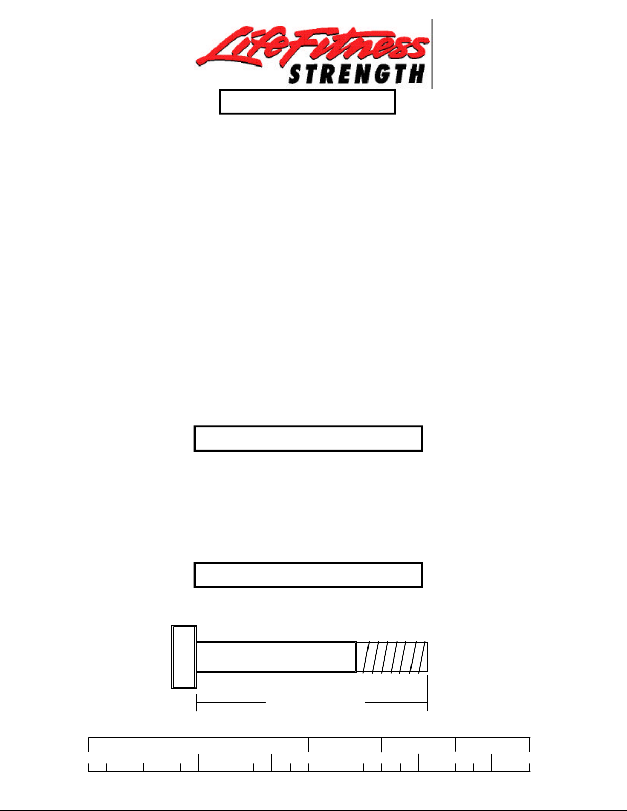
Bolt Length Ruler
NOTE: BOLT LENGTH IS MEASURED FROM THE UNDERSIDE OF THE HEAD OF THE BOLT.
BOLT LENGTH
BOLT LENGTH RULER:
1/2 1/2 1/2 1/2 1/2 1/2
0
1
2
3 4 5
2
6
Page 3
PARTS LIST
KEY
1
2
3
PART #
6284501
6812801
6382301
DESCRIPTION
25 HOLE WEIGHT STACK SHAFT
166-5/8” CABLE ASSEMBLY
WEIGHT PLATE BUSHING 10 CT
QTY
1
1
1
KEY
4
5
6
PART #
6703801
6198501
6214501
CABLE
DESCRIPTION
WEIGHT STACK LABEL (lbs.)
WEIGHT STACK LABEL (1-25)
WEIGHT PLATES
SHROUD
QTY
.1
1
5
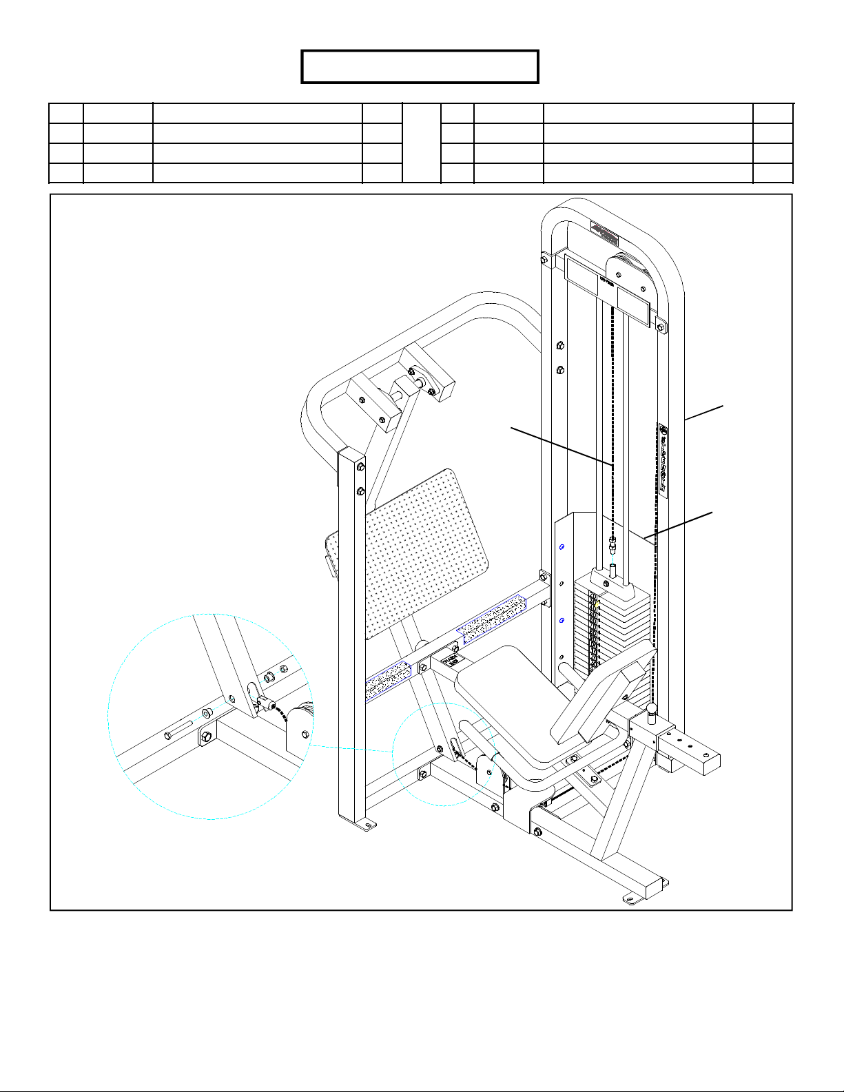
TOWER
FIGURE 1
STEP 1:
• Unscrew the threaded end of the CABLE (68074) from the WEIGHT STACK SHAFT of the HEAD PLATE.
• Completely remove CABLE (68074 ) from the TOWER BRACE, LOWER CROSS SUPPORT, BENCH FRAME, and LEG PEDESTAL.
See FIGURE 1. (NOTE: It may be necessary to loosen and remove some pulleys before removing the cable.)
• Discard CABLE ( 68074).
• Remove the SHROUD from TOWER for ease of assembly.
3
Page 4

3
6
FIGURE 2
STEP 2:
• Snap two WEIGHT PLATE BUSHINGS (3) into the top of all five WEIGHT PLATES (6) as shown in FIGURE 2.
FIGURE 3
TOWER
TOWER
BRACE
1/2 X 4” BOLT
(EXISTING)
GUIDE
RODS
SHAFT
COLLARS
STEP 3:
• Remove two 1/2 X 4” BOLTS, two 1/2” WASHERS, and two 1/2” LOCK NUTS from the TOWER BRACE to remove the TOWER
BRACE from the TOWER and GUIDE RODS as shown in FIGURE 3.
• LOOSEN the SHAFT COLLAR SET SCREWS and slide them off the GUIDE RODS.
1/2 1/2 1/2 1/2 1/2 1/2
0
1
2
3 4 5
4
6
Page 5

HEAD PLATE
TOWER
GUIDE ROD
4
• Unbolt the old WEIGHT STACK SHAFT from the HEAD
PLATE and replace it with the new 25 HOLE WEIGHT
STACK SHAFT (1). (NOTE: The bolt hole in the HEAD
PLATE should be on top. Please discard the old WEIGHT
STACK SHAFT.)
1
6
5
WEIGHT
STACK
CUSHION
• Attach the WEIGHT STACK LABELS (4) (#’s 220-260) or
(5) (21-25) to the five WEIGHT PLATES (6) as shown on
FIGURE 4.
• Insert the two GUIDE RODS through the two WEIGHT
STACK CUSHIONS into the base of the TOWER as
shown in FIGURE 4. Lubricate the GUIDE RODS with a
silicon or teflon spray that is available at most hardware
stores.
• USING EXTREME CARE, slide the five new WEIGHT
PLATES (6) and the previous twenty WEIGHT PLATES
down over the GUIDE RODS onto the WEIGHT STACK
CUSHIONS. (NOTE: Make sure that the key holes of the
WEIGHT PLATES all face the same way.)
• Carefully Slide the new HEAD PLATE ASSEMBLY down
over the GUIDE RODS onto the weight stack as shown in
FIGURE 4.
FIGURE 4
5
Page 6

FIGURE 5
TOWER
BRACE
1/2 X 4” BOLT
(EXISTING)
TOWER
GUIDE
RODS
SHAFT
COLLARS
STEP 5:
• Place TOWER BRACE over the GUIDE RODS and securely fasten TOWER BRACE to TOWER using previously removed 1/2” X 4”
BOLTS, 1/2” WASHERS, AND 1/2” NUTS as shown in FIGURE 5.
• Slide the SHAFT COLLARS to the top of the GUIDE RODS and SECURELY tighten the SHAFT COLLAR SET SCREWS .
TOWER
STEP 6:
• Route loop end of new CABLE (68128) (2) around pulleys
in TOWER BRACE, LOWER CROSS SUPPORT, AND
BENCH FRAME, then fasten to LEG PEDESTAL as shown
in FIGURE 6.
• Retighten any loosened pulley connections.
• Reassemble SHROUD to the TOWER.
CABLE
SHROUD
FIGURE 6
1/2 1/2 1/2 1/2 1/2 1/2
0
1 2 3 4 5
6
6
Page 7

2
1
FIGURE 7
STEP 7:
• Screw the threaded end of the new CABLE (68128) (2) approximately 3/4” into the end of the WEIGHT STACK SHAFT (1) and
tighten jam nut securely.
• If the HEAD PLATE does not sit on top of the first WEIGHT PLATE, push the head plate down, insert the SELECTOR PIN and
perform several repetitions on the machine. This will relax the cable system and prevent the HEAD PLATE from lifting up.
• If after completing the previous step, the HEAD PLATE still does not sit on top of the first WEIGHT PLATE or if there is excess
slack in the cable system, adjust the threaded end of the CABLE accordingly and retighten the jam nut.
Thank you for purchasing the LifeFitness 8246 50 LB. ADD-ON KIT. If unsure of proper use of equipment, call your local
LifeFitness distributor or call the LifeFitness customer service department at (800) 328-9714.
7
 Loading...