

Page 1
8205 CABLE CROSS OVER
ASSEMBLY INSTRUCTIONS
1Part # 6790401 Revision: 7/13/98
Page 2

IMPORTANT NOTES
Please note:
* Thank you for purchasing the LIFE FITNESS 8205 CABLE CROSS OVER. Please read these instructions thoroughly and
keep them for future reference. This product must be assembled on a flat, level surface to assure its proper function.
* We recommend cleaning your product (pads and frame) on a regular basis, using warm soapy water. Touch-up paint can be
purchased from your LIFE FITNESS customer service representative at (800) 328-9714.
There is a risk assumed by individuals who use this type of equipment. To minimize risk, please follow these rules:
1. Inspect equipment daily. Tighten all loose connections and replace worn parts immediately. Failure to do so may
result in serious injury.
2. Do not allow minors or children to play on or around this equipment.
3. Exercise with care to avoid injury.
4. If unsure of proper use of equipment, call your local LIFE FITNESS STRENGTH distributor or call the LIFE FITNESS
STRENGTH customer service department at (800) 328-9714.
5. Consult your physician before beginning any exercise program.
Tools Required for Assembly
* Rubber mallet or hammer
* 3/4” wrench
* 9/16” wrench
* Ratchet with 3/4” and 9/16” sockets
* 5/16” Allen wrench,
* Adjustable wrench
* Tape measure
2
Page 3
KEY
1
2
3
4
5
6
7
8
9
10
11
12
13
14
15
16
17
18
19
20
21
PART #
6788503
6744102
6789002
6744803
6789102
6789403
6789703
6788203
6788103
6459401
6785602
3202402
3116101
3116201
6793201
6284501
6714601
6790101
6020601
6480301
6214401
DESCRIPTION
TOWER
NOVATRAK SWIVEL
CENTER PULLEY BRACKET
TOWER BRACE
SWIVEL HOLDER
LOWER PULLEY HOUSING
SWIVEL UPRIGHT
UPPER PULLEY HOUSING
CHIN-UP SUPPORT
81” GUIDE ROD
SHROUD
1/2 X 3/4” BTN HD CAP SCREW
4-1/2” PULLEY
3-1/2” PULLEY
STRAP
WEIGHT STACK SHAFT
HEAD PLATE
CABLE
1/2” FLANGE BEARING
3/8” FLANGE SPACER
WEIGHT STACK PIN
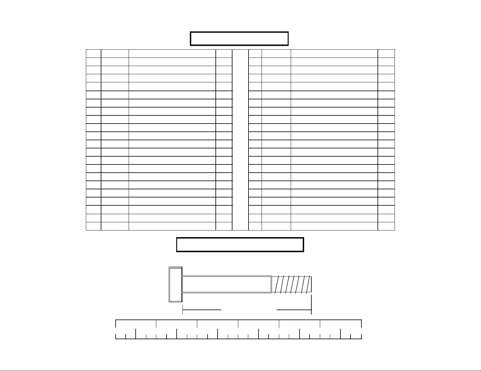
PARTS LIST
QTY
2
2
2
2
2
2
2
2
1
4
2
2
14
2
2
2
2
2
4
20
2
KEY
22
23
24
25
26
27
28
29
30
31
32
33
34
35
36
37
38
39
40
41
42
PART #
3108002
6382301
3103801
6412001
3102501
3102502
3102802
3102801
3102804
3202401
3102901
3102933
3102922
3202101
3102918
3202103
3102944
6703801
6189501
6214501
3103302
DESCRIPTION
WEIGHT STACK CUSHION
PLATE BUSHING (10 CT.)
5/16” SNAP HOOK
3/8” SPRING PIN ASSEMBLY
3/8" FLAT WASHER
1/2" FLAT WASHER
3/8” LOCK NUT
1/2" LOCK NUT
1/2" LOW HT LOCK NUT
3/8 X 1” BTN HD CAP SCREW
3/8 X 1-1/4" BOLT
3/8 X 2" BOLT
3/8 X 2-3/4” BOLT
1/2 X 1-1/4" BOLT
1/2 X 3-1/4” BOLT
1/2 X 4” BOLT
1/2 X 5” BOLT
WEIGHT STACK LABEL (LBS.)
WEIGHT STACK LABEL (1-25)
WEIGHT PLATE
13/16” SHAFT COLLAR
QTY
4
8
2
2
2
12
16
18
6
8
2
6
10
8
6
10
2
2
2
40
4
BOLT LENGTH RULER:
0
1/2 1/2 1/2 1/2 1/2 1/2
1 2 3 4 5 6
Bolt Length Ruler
NOTE: Bolt length is measured from the underside of the head of the bolt.
BOLT LENGTH
3
Page 4
1
1
37 1/2 X 4”
29
6
1/2 X 4” 37
29
6
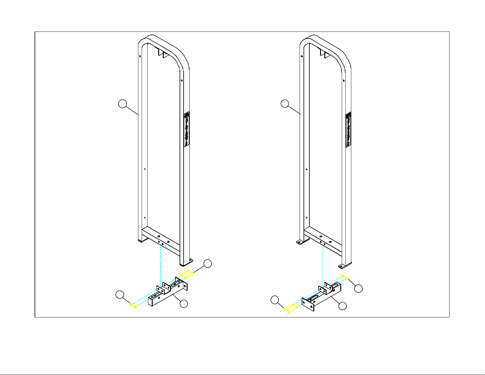
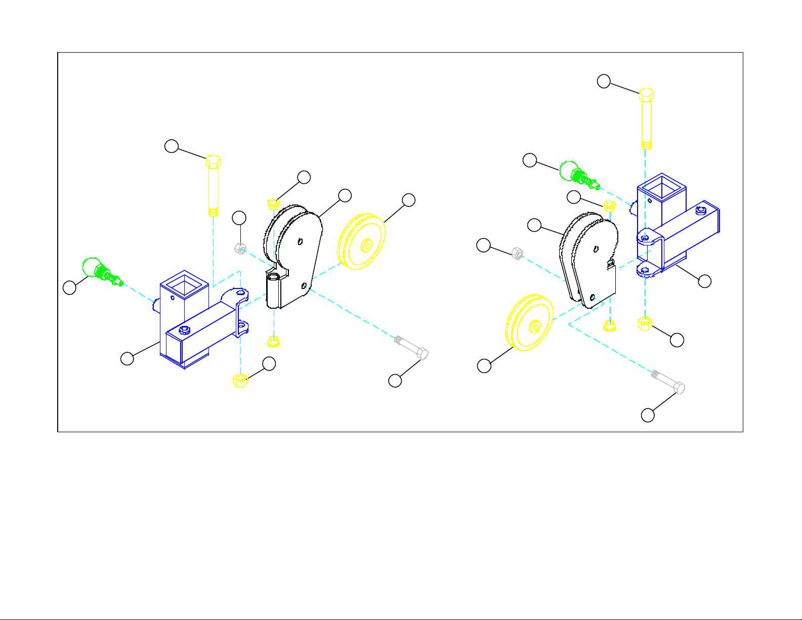
FIGURE 1
STEP 1
• LOOSELY assemble the two LOWER PULLEY HOUSINGS (6) to the two TOWERS (1) using four 1/2 X 4” BOLTS (37) and four 1/2” LOCK NUTS (29) as shown in
FIGURE 1.
4
Page 5
8
1
29
36
1/2 X 3-1/4”
29
8
36
1/2 X 3-1/4”
1
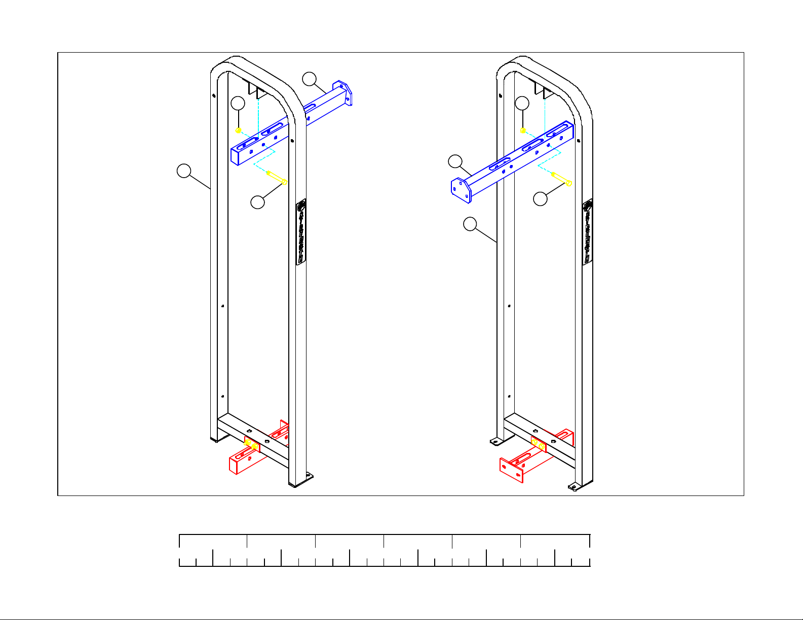
FIGURE 2
STEP 2
• LOOSELY assemble the two UPPER PULLEY HOUSINGS (8) to the two TOWERS (1) using two 1/2 X 3-1/4” BOLTS (36) and two 1/2” LOCK NUTS (29) as shown in
FIGURE 2.
0
1/2 1/2 1/2 1/2 1/2 1/2
1 2 3 4 5 6
5
Page 6
1/2 X 4” 37
1/2 X 4” 37
25
19
25
5
2
28
29
3/8 X 2” 33
14
2
28
14
FIGURE 3
STEP 3
• SECURELY assemble two 3-1/2” PULLEYS (14) to the two NOVATRAK SWIVELS (2) using two 3/8 X 2” BOLTS (33) and two 3/8” LOCK NUTS (28). See FIGURE 3.
• Insert two 1/2” FLANGE BEARINGS (19) into each end of the NOVATRAK SWIVELS (2) and assemble them to the SWIVEL HOLDERS (5) using two 1/2 X 4” BOLTS
(37), and two 1/2” LOCK NUTS (29). (NOTE: Tighten connection enough to remove play, yet allowing the SWIVEL HOLDER (2) to rotate freely.) See FIGURE 3.
19
5
29
3/8 X 2” 33
• SECURELY assemble two 3/8” SPRING PIN ASSEMBLIES (25) to the SWIVEL HOLDERS (5). See FIGURE 3.
6
Page 7

STEP 4
• Pull back the SPRING PINS on the SWIVEL HOLDERS
(5) and slide assemblies over the SWIVEL UPRIGHTS
(7) as shown in FIGURE 4.
• LOOSELY assemble the two SWIVEL UPRIGHTS (7)
to the LOWER PULLEY HOUSING (6) using four 1/2
X 3-1/4” BOLTS (36), four 1/2” WASHERS (27), and
four 1/2” LOCK NUTS (29) as shown in FIGURE 4.
FIGURE 4
29
5
29
5
8
27
38
1/2 X 5”
• LOOSELY assemble the SWIVEL UPRIGHTS (7) to
the UPPER PULLEY HOUSING (8) using two 1/2 X
5” BOLTS (38), four 1/2” WASHERS (27), and two 1/
2” LOCK NUTS (29) as shown in FIGURE 4.
• SECURELY assemble all loose connections made to
this point.
29
8
6
27
38
1/2 X 5”
7
7
6
29
27
36 1/2 X 3-1/4”
36 1/2 X 3-1/4”
27
0
1/2 1/2 1/2 1/2 1/2 1/2
1 2 3 4 5 6
7
Page 8

STEP 5
• SECURELY assemble the CHIN-UP SUPPORT (9) to
the two UPPER PULLEY HOUSINGS (8) using six
1/2 X 1-1/4” BOLTS (35) and six 1/2” LOW
HEIGHT LOCK NUTS (30) as shown in FIGURE 5.
FIGURE 5
9
1/2 X 1-1/4” 35
30 LOW HT.
8
8
7
Page 9

• Loop the ball end of the CABLE (18) around one 4-1/
2” PULLEY (13) and SECURELY assemble the 4-1/
2” PULLEY (13) to the NOVATRAK SWIVEL (2)
using one 3/8 X 2” BOLT (33) and one 3/8” LOCK
NUT (28) as shown in FIGURE 6.
FIGURE 6
28
13
• Route the threaded end of the CABLE (18) through
the opening in the UPPER PULLEY HOUSING (8)
and around two 4-1/2” PULLEYS (13) as shown in
FIGURE 6.
• SECURELY assemble the two 4-1/2” PULLEYS
(13) to the UPPER PULLEY HOUSING (8) using
two 3/8 X 2-3/4” BOLTS (34), four 3/8” FLANGE
SPACERS (20), and four 3/8” LOCK NUTS (28).
See FIGURE 6.
20
8
3/8 X 2-3/4” 34
18
2
28
13
3/8 X 2” 33
0
1/2 1/2 1/2 1/2 1/2 1/2
1 2 3 4 5 6
9
Page 10

FIGURE 7 FIGURE 8
35 1/2 X 1-1/4”
3
3
FIGURE 9
32 3/8 X 1-1/4”
26
17 31
16
STEP 7:
• SECURELY assembly the CENTER PULLEY
BRACKETS (3) to the WEIGHT STACK SHAFTS
(16) using one 1/2 X 1-1/4 BOLT (35) as shown in
FIGURE 7.
16
STEP 8:
• Slide HEAD PLATES (17) up the WEIGHT STACK
SHAFTS (16) and SECURELY assemble the CEN-
TER PULLEY BRACKETS (3) to the HEAD
PLATES (17) using two 3/8 X 1-1/4” BOLTS (32) and
two 3/8” WASHERS (26) as shown in FIGURE 8.
49
STEP 9:
• Snap two WEIGHT PLATE BUSHINGS (23) each,
into the top side of the forty WEIGHT PLATES (41)
as shown in FIGURE 9.
10
Page 11

STEP 10:
• Insert the two GUIDE RODS (10) into the base of the
TOWER (1) as shown in FIGURE 10. Lubricate the
GUIDE RODS with a slicon or teflon spray that is
available at most hardware stores.
• Slide two WEIGHT STACK CUSHIONS (22) down
over the GUIDE RODS (10). See FIGURE 10.
• Using EXTREME CARE slide twenty WEIGHT
PLATES (41) down over the GUIDE RODS (10) with
the key-hole facing as shown in FIGURE 10.
10
41
1
22
FIGURE 10
1/2 1/2 1/2 1/2 1/2 1/2
0 1 2 3 4 5 6
11
Page 12

STEP 11:
• Run CABLE (18) under and around the 4-1/2” PULLEY
(13) and SECURELY assemble the 4-1/2” PULLEY (13)
to the CENTER PULLEY BRACKET (3) using one 3/8 X
2” BOLT (33) and one 3/8” LOCK NUT (28). See
FIGURE 11.
• Carefully slide the HEAD PLATE ASSEMBLY (17) down
over the GUIDE RODS (10) onto the weight stack as
shown in FIGURE 11.
18
13
FIGURE 11
12
28
10
3
33 3/8 X 2”
17
Page 13

42
27
4
29
1
10
1/2 X 4” 37
FIGURE 12
STEP 12
• Slide two 13/16” SHAFT COLLARS (42) down over the GUIDE RODS (10) as shown in FIGURE 12.
• Slide the TOWER BRACE (4) over the GUIDE RODS (10) as shown in FIGURE 12.
• SECURELY assemble the TOWER BRACE (4) to the TOWER (1) using two 1/2 X 4” BOLTS (37), two 1/2” WASHERS (27), and two 1/2” LOCK NUTS (29) as shown in
FIGURE 12.
1/2 1/2 1/2 1/2 1/2 1/2
0 1 2 3 4 5 6
13
Page 14

STEP 13:
• Loop the threaded end of the CABLE (18) around a 4-1/
2” PULLEY (13) and SECURELY assemble the 4-1/2”
PULLEY (13) to the UPPER PULLEY HOUSING (8)
using one 3/8 X 2-3/4” BOLT (34), two 3/8” FLANGE
SPACERS (20), and two 3/8” LOCK NUTS (28). See
FIGURE 13.
• Slide the 13/16” SHAFT COLLARS (42) to the top of
the GUIDE RODS (10) and SECURELY tighten the set
screws of the SHAFT COLLARS (42). See FIGURE 13.
FIGURE 13
13
28
18
20
8
34 3/8 X 2-3/4”
42
14
Page 15

STEP 14:
• Route the threaded end of the CABLE (18) through the
LOWER PULLEY HOUSING (6) as shown in FIGURE 14.
• Slip one 4-1/2” PULLEY (13) over the CABLE (18) and
SECURELY assemble the 4-1/2” PULLEY (13) to the
LOWER PULLEY HOUSING (6) using one 3/8 X 2-3/4”
BOLT (34), two 3/8” FLANGE SPACER (20) and one 3/8”
LOCK NUT (28) as shown in FIGURE 14. (Make sure the
CABLE is in the groove of the PULLEY.)
18
28
STEP 15:
• Slip one 4-1/2” PULLEY (13) over the CABLE (18) and
SECURELY assemble the 4-1/2” PULLEY (13) to the
LOWER PULLEY HOUSING (6) using one 3/8 X 2-3/4”
BOLT (34), two 3/8” FLANGE BEARINGS (20) and one
3/8” LOCK NUT (28) as shown in FIGURE 15. (Make
sure the CABLE is in the groove of the PULLEY.)
FIGURE 14
FIGURE 15
28
13
18
20
20
34 3/8 X 2-3/4”
13
6
6
34 3/8 X 2-3/4”
1/2 1/2 1/2 1/2 1/2 1/2
0 1 2 3 4 5 6
15
Page 16

STEP 16
• Screw the threaded end of CABLE (18) approximately 3/4” into the
SWIVEL HOLDER (5) and tighten jam nut SECURELY as shown
in FIGURE 16.
FIGURE 16
12
5
• SECURELY assemble one 1/2 X 3/4” BUTTON HEAD CAP
SCREW (12) to the SWIVEL HOLDER (5). See FIGURE 16.
• Attach one 5/16” SNAP HOOK (24) and one STRAP (15) to the ball
end of the CABLE (18). See FIGURE 16.
• Apply one set of WEIGHT STACK LABELS - LBS. OR 1-25 (39)
(40) to each WEIGHT PLATE (41) as shown in FIGURE 16.
• Insert the WEIGHT STACK PIN (21) into the first WEIGHT PLATE
(41) of the WEIGHT STACK as shown in FIGURE 16.
• If the HEAD PLATE (17) does not sit on top of the first WEIGHT
PLATE (41), push the head plate down, insert the SELECTOR PIN
(21) and perform several repetitions on the machine. This will relax
the cable system and prevent the HEAD PLATE (17) from lifting up.
• If after completing the previous step the HEAD PLATE (17) still
does not sit on top of the first WEIGHT PLATE (41) or if there is
excess slack in the cable system, adjust the threaded end of the
CABLE (18) accordingly and RETIGHTEN the jam nut.
15
24
21
39
18
17
40
41
• Repeat STEPS 6-16 to assemble cable on other
side of the CABLE CROSS OVER.
16
Page 17

3/8 X 1” 31
BUTTON
HEAD
11
MAKE SURE
CABLE IS
ROUTED
BEHIND
SHROUD!
1
FIGURE 17
STEP 17:
• SECURELY assemble the SHROUD (11) to the TOWER (1) using four 3/8 X 1” BUTTON HEAD CAP SCREWS (31) as shown in FIGURE 17.
• Repeat STEP 17 to assemble SHROUD on other side of the CABLE CROSS OVER.
1/2 1/2 1/2 1/2 1/2 1/2
0 1 2 3 4 5 6
17
Page 18

STEP 18:
• Make sure all connections are tight and secure.
Thank you for purchasing the LifeFitness 8205
CABLE CROSS OVER. If unsure of proper use
of equipment, call your local LifeFitness distributor or call the LifeFitness customer service
department at (800) 328-9714.
FIGURE 18
18
 Loading...