

Model 5500HR Treadmill
Customer Support Services
SERVICE MANUAL

©1996 Life Fitness. All rights reserved. The Life Fitness trademark is register in the U.S. Patent and Trademark Office,
Certificate No. 1,400,502, issued July 8, 1986. FlexDeck, Zone Trainer and Heart Rate Zone Training are trademarks of
Life Fitness. Any use of these trademarks, without the express written consent of Life Fitness, is forbidden.
U.S. Patent Numbers 3,767,195 and 4,358,105.
M051-00K36-A032
12-96

Life Fitness Model 5500HR Treadmill
INTRODUCTION
HOW TO USE THIS SERVICE MANUAL
In the unlikely event that an operating problem may occur with your Life Fitness model 5500HR aerobic trainer,
this Service Manual will instruct and guide you on the quickest, most efficient manner in which to approach the
situation. This Service Manual has been separated into a total of Five Sections for quick reference:
q INTRODUCTION
q TABLE OF CONTENTS
Section I
q TROUBLESHOOTING GUIDES
Section II
q DIAGNOSTIC TESTS
Section III
q MODEL 5500HR "How To..." GUIDES
Section IV
q PARTS IDENTIFICATION
Section V
q WIRING DIAGRAMS
q PREVENTIVE MAINTENANCE
q COMMUNICATING BY FAX
If an operating problem should arise, turn to the TROUBLESHOOTING GUIDES and attempt to isolate what is
causing the malfunction. The GUIDES are listed by symptoms and follow with suggestions as to the most probable
cause of the problem.
Once you have pin pointed the source of the problem, turn to the appropriate "How To..." section and review the
proper procedures for removing, replacing or adjusting a part. The "How To..." sections are organized by
replaceable part (or assembly) name and each page lists the “Tools Required“ to complete that specific function.
Refer to Section IV to identify the proper name and number of the part you will now need to order to repair your
machine. A form to order by FAX has also been included in Section V for your convenience.
To order a part, call Life Fitness Customer Support Services any Monday through Friday from 8:00 AM to 6:00 PM
(C.S.T.). When you place a call, in order to speed our response to your particular situation, please have the
following information available for the customer support phone technician who will be prepared to assist you:
1. The Treadmill model type (5500HR)
2. The six digit serial number ( Located next to the ON/OFF switch )
Serial Number:
3. The symptom of the problem you are experiencing
4. The part name and number you need to order
When you receive your order, review the appropriate "How To..." section and follow the step by step procedures
designed to help you install the part quickly and correctly.
If you have any questions or comments please phone, mail, or fax us at one of the numbers listed below.
CUSTOMER SUPPORT SERVICES
10601 Belmont Avenue, Franklin Park, IL 60131
Phone (800) 351-3737 Toll Free or (847) 451-0036 FAX (800) 216-8893 Toll Free or (847) 288-3702

Life Fitness Model 5500HR Treadmill
TABLE OF CONTENTS
Introduction (How To Use This Service Manual)
Table of Contents
SECTION I Page
Troubleshooting Guides
Belt Slips Or Display Reads Error..............................................................................................1
Noisy Treadmill...........................................................................................................................2
Display Does Not Illuminate Or Respond To Input....................................................................3
Unit Resets Randomly................................................................................................................4
No Power.....................................................................................................................................5
Striding Belt Comes In Contact With Frame And End Caps......................................................6
Display Reads Errors..................................................................................................................7
Lift Error......................................................................................................................................8
Heart Rate System ......................................................................................................................9
SECTION II
Diagnostic Tests.......................................................................................................................................1-4
SECTION III
How To...REMOVE AND REPLACE THE
How To...ADJUST AND TENSION THE STRIDING BELT .......................................................................... 12,13
SECTION IV
Parts Identification ................................................................................................................................... 1-3
SECTION V
Wiring Block Diagram............................................................................................................................... 1
Preventive Maintenance Tips................................................................................................................... 2
Communicating By Fax............................................................................................................................3,4
Motor Cover.................................................................................................................................1
Heatsink Control Board ..............................................................................................................2,3
Drive Motor Belt.......................................................................................................................... 4,5
Drive Motor Assembly................................................................................................................6
Rear End Cap Panel .................................................................................................................... 7
Front Roller Assembly................................................................................................................8
Rear Roller Assembly................................................................................................................. 9
Deck.............................................................................................................................................10
Striding Belt ................................................................................................................................ 11
Display Console..........................................................................................................................14
Telemetry Receiver .....................................................................................................................15
Lift Actuator ................................................................................................................................ 16
On/Off Switch..............................................................................................................................17
Choke...........................................................................................................................................18
Transformer.................................................................................................................................19

Life Fitness Model 5500HR Treadmill
TROUBLESHOOTING GUIDE
Symptom: "Slowdown". Belt slips during footfall or desired speed is reduced.
Malfunction Probable Cause Corrective Action
Belt slips during footfall
Desired speed is reduced
Insufficient power source.
Belt slips on front roller during
stall test.
Drive belt slips on sheave.
User is pushing striding belt.
Belt/Deck Malfunction.
• Deck laminate is worn
through.
• Underside of striding belt is
worn or glazed (hard,
glossy).
q Plug treadmill into a dedicated 120V,
15 amp circuit. (See Operations
Manual)
q Check belt & re-tension as necessary.
q Check belt & re-tension as necessary.
q Inspect belt and deck for excessive
wear. Replace any defective part.
q Perform "Power Mode” test.
(See Diagnostics Section)
q Replace deck and belt.
For Assistance Call:
Life Fitness Customer Support Services
1-847-451-0036 or 1-800-351-3737
1

Life Fitness Model 5500HR Treadmill
TROUBLESHOOTING GUIDE
Symptom: Noisy Treadmill
Malfunction Probable Cause Corrective Action
Knocking sound at rear of
machine
Knocking sound coming
from deck
Rubbing sound from
underneath machine
Squeaking noise
Squeaking noise at higher
speeds
Loud "groaning" sound
heard from front of
machine while elevating
Loud "groaning" on
footfall
Wax build-up on roller
Faulty rear roller bearings.
Loose deck screws.
Foreign objects may be stuck
underneath the machine.
Lifesprings may be misaligned.
Drive Motor Belt may be worn
or damaged.
Noisy Drive Motor.
Drive Motor Belt may be
squeaking.
Noisy Drive Motor.
Faulty Lift Motor.
Faulty Drive Motor.
High deck and belt friction.
q Run unit for 10 hours of ontime use to
distribute wax evenly
q Replace rear roller assembly.
q Tighten deck screws.
q Inspect underneath belt and machine.
Remove any debris or accumulation on
debris brush.
q Reposition Lifesprings.
q Replace Drive Motor Belt.
q Replace Drive Motor.
q Spray with gear/belt lubricant.
q Align pulleys if necessary.
q Replace Drive Motor.
q Replace Lift Motor.
q Replace Drive Motor.
q Perform "Power Mode” test.
(See Diagnostics Section)
For Assistance Call:
Life Fitness Customer Support Services
1-847-451-0036 or 1-800-351-3737
2

Life Fitness Model 5500HR Treadmill
TROUBLESHOOTING GUIDE
Symptom: Display Does Not Illuminate or Respond To Input
Malfunction Probable Cause Corrective Action
Display does not illuminate
when machine is powered
on.
Insufficient power source.
Pinched wire connection
Loose connection at Display
Console or Heatsink Control
Board.
Faulty Display Console.
Faulty Heatsink Control Board.
q Plug treadmill into a dedicated 120V, 15
amp circuit
q Turn power ON at switch while pressing
the Speed Down ∇ Key and perform
Display test.
q Check all electrical connections.
q Check cable in Control Panel for pinched
cable
q Secure connections at Display Console
and Heatsink Control Board.
q Replace Display Console.
q Check all electrical connections.
q Replace Heatsink Control Board.
For Assistance Call:
Life Fitness Customer Support Services
1-847-451-0036 or 1-800-351-3737
3

Life Fitness Model 5500HR Treadmill
TROUBLESHOOTING GUIDE
Symptom: Unit Resets Randomly
Malfunction Probable Cause Corrective Action
Unit resets randomly
Insufficient power source.
Damaged line cord.
Line cord improperly seated in
socket.
Pinched display harness.
Loose connections at heatsink
control board and display.
Safety key not making proper
contact.
Faulty safety key switch
q Plug treadmill into a dedicated 120V,
15 amp circuit.
q Replace line cord.
q Inspect power connection at electrical
outlet and at machine for proper contact.
q Check all display connections.
q Verify cable from Display to handrail
cable is not crimped between (tray)
Control Panel and the handrail.
q Replaced damaged cable.
q Secure connections at heatsink control
board and display.
q Place safety key in proper position.
q Replace switch.
For Assistance Call:
Life Fitness Customer Support Services
1-847-451-0036 or 1-800-351-3737
4

Life Fitness Model 5500HR Treadmill
TROUBLESHOOTING GUIDE
Malfunction Probable Cause Corrective Action
Symptom: No Power
No Power
I/O or On/Off switch.
Insufficient power source.
Safety key at I/O switch
Damaged line cord.
Line cord improperly seated in
socket.
Pinched cable in Control Panel
Power module.
• On/Off switch
• Heatsink
q Is unit turned on?
q Plug treadmill into a dedicated 120V, 15
amp circuit.
q Using a meter, verify power at outlet.
q Safety key broken or missing. Replace
safety key.
q Replace line cord.
q Inspect power connection at electrical
outlet and at machine for proper contact.
q Verify cable from Display to handrail
cable is not crimped between (tray)
Control Panel and the handrail.
q Replaced damaged cable.
q Replace faulty parts
Faulty Display Console.
Life Fitness Model 5500HR Treadmill
q OHM ON/OFF switch for continuity.
q Using a meter, check for voltage at TP1
for 5v DC and TP2 for 8v DC with
respect to ground.
For Assistance Call:
Life Fitness Customer Support Services
1-847-451-0036 or 1-800-351-3737
5

TROUBLESHOOTING GUIDE
Symptom: Belt Comes In Contact With Frame and Rear End Cap Panel
Malfunction Probable Cause Corrective Action
The belt is traveling beyond
the tracking guides.
Striding belt mis-alignment
by more than 1/4”.
Worn striding belt
Striding belt needs to be
re-tensioned.
User pushes belt.
Unit is not level.
Belt Skewed
q Replace worn belt.
q Refer to belt tensioning procedure in
operation or service manual.
q Center belt according to belt centering
technique described in operation
manual.
q Level treadmill by adjusting leveling
legs.
q Replace front roller bolt with Belt skew
kit.
For Assistance Call:
Life Fitness Customer Support Services
1-847-451-0036 or 1-800-351-3737
6

Life Fitness Model 5500HR Treadmill
TROUBLESHOOTING GUIDE
Malfunction Probable Cause Corrective Action
Symptom: Display reads Errors
Belt Moving Error
No ZX
Belt Over Speed
No Blanking
Loose connections at electrical
outlet.
User has overdriven belt.
Loose cable connection.
Opto Sensor not in the proper
position.
Dust or other obstrustion
blocking opto sensor from
reading.
Faulty opto sensor.
User has overdriven belt.
Display has been taken out of
its screen saver mode.
q Verify the plug is seated properly in the
electrical outlet.
q Reset the unit.
q Check cable connection at Console
and CPU board.
q Adjust opto sensor.
q Clean opto sensor.
q Replace faulty opto sensor.
q Reset the unit.
q Power unit off and on to reset
screensaver mode.
Stop, Stop, Stop
Safety Key not making proper
contact
Faulty Safety Key Switch
q Verify Safety Key is in proper position
q Replace Safety Key Switch in Control
Panel
For Assistance Call:
Life Fitness Customer Support Services
1-847-451-0036 or 1-800-351-3737
7

Life Fitness Model 5500HR Treadmill
TROUBLESHOOTING GUIDE
Symptom: Lift Error
Malfunction Probable Cause Corrective Action
Unit will not incline
Line cord in postioned over the
lift leg assembly
Faulty Home Switch.
Faulty Lift Actuator.
Unit will not elevate to 15%
.
q Position the line cord to its proper
position.
q Perform incline test (See Diagnostics).
q Preform incline test (See Diagnostics).
If unit elevates , check home switch
with an ohm meter. Replace faulty
Home Switch.
q Replace Lift Actuator.
q Check calibration of Lift Motor.
For Assistance Call:
Life Fitness Customer Support Services
1-847-451-0036 or 1-800-351-3737
8
Life Fitness Model 5500HR Treadmill
TROUBLESHOOTING GUIDE
Symptom: Heart Rate System Does Not Respond, Erratic Heart Rate Reading
Symptom Probable Cause Corrective Action
No heart rate or display
reads (No chest strap
detected) Erratic Heart
Rate
HR receiver not installed.
No HR transmitter (Chest
strap).
Electrodes on transmitter are
dry.
No HR reading.
HR receiver may be near an
electrical device that could
interfere with the HR (i.e.
television).
HR connector not plugged in.
Check for pinched wire.
Bad HR receiver or
transmitter.
Bad display console.
q Install HR receiver into HR receiver jack
on underside of handlebar tray.
q Install transmitter (chest strap).
q Wet electrodes on transmitter.
q Enter into DIAGNOSTICS test to verify a
good heart rate (See Section II).
q Move treadmill to another location.
q Plug HR connector to display console.
q Replace HR harness cable.
q Replace HR receiver and/or transmitter.
q Replace display console.
For Assistance Call:
Life Fitness Customer Support Services
1-847-451-0036 or 1-800-351-3737
9

Life Fitness Model 5500HR Treadmill
NOTES:
10
Life Fitness Model 5500HR Treadmill
DIAGNOSTIC TESTS
PURPOSE:
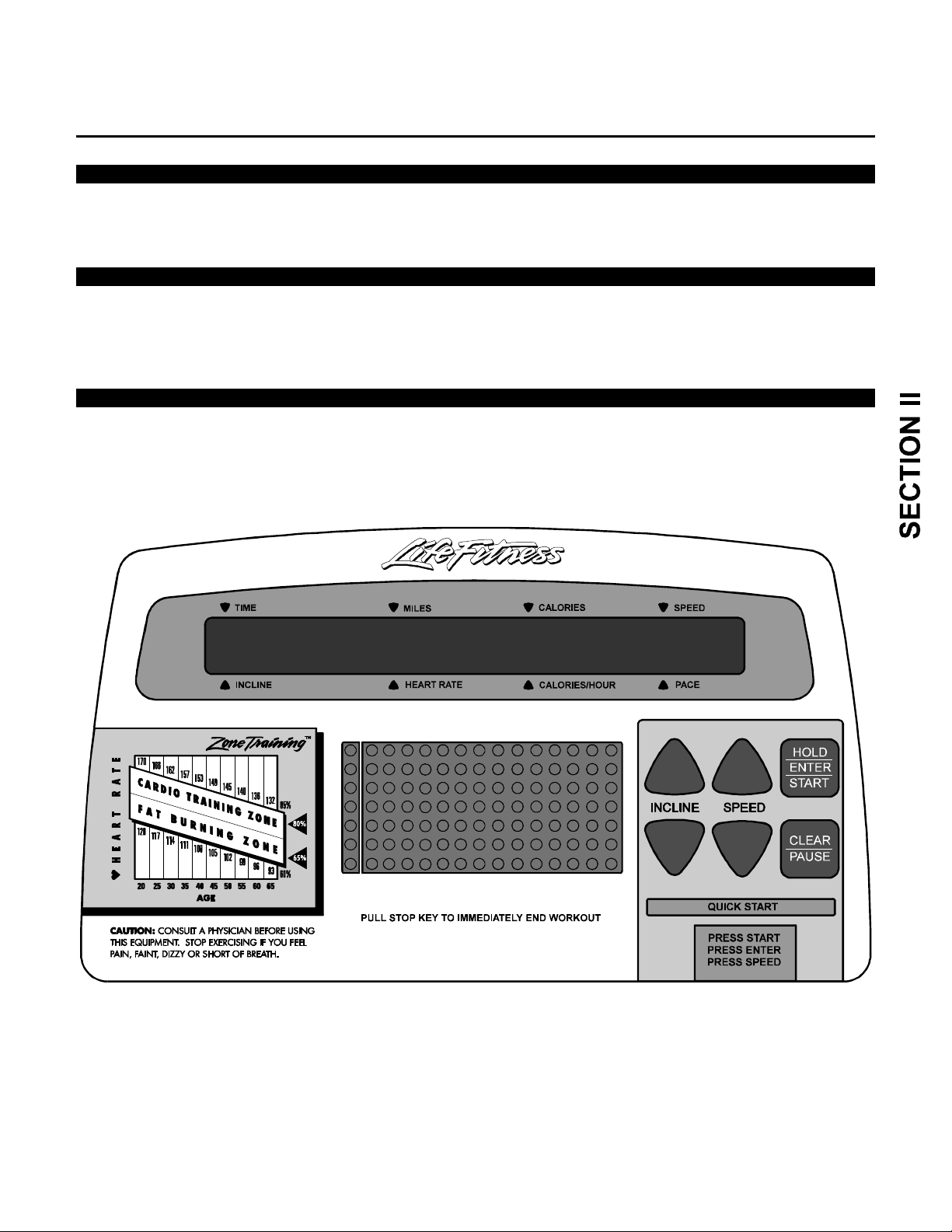
This Section describes the test procedures for the Life Fitness 5500HR Treadmill Display Console Board including
those for the Heart Rate feature.
SCOPE:
Diagnostic procedures will test the Display Console Board as used in the final Treadmill assembly. These
procedures will insure proper functioning of the Console LED’s, Keys and Displays as well as identify the Console
version.
PROCEDURE:
Begin with the Treadmill ON/OFF switch turned to OFF. To enter diagnostic mode, you must power unit ON while
pressing the designated key for each mode of the diagnostics.
(Continued)
1

Life Fitness Model 5500HR Treadmill
DIAGNOSTIC TESTS ( Continued )
The SPEED DOWN KEY is used for the following testing information:
⇒ CHECK THE DISPLAY/KEYPAD FUNCTIONS
⇒ REVIEW STATISTICS
⇒ IDENTIFY SOFTWARE VERSION
Start with the Life Fitness model 5500HR treadmill turned OFF at the I/O switch.
To advance through this test, use the ENTER KEY.
Power up the unit while holding the SPEED DOWN KEY ∇. All LED’s on the Display Console will light.
Press ENTER once, and Console should begin to scroll through lighting LED’s individually.
Press ENTER a second time and this will bring you to the Keypad test. By pressing each key, a pattern
of LED’s will light. This shows that the button is responding.
Press ENTER a third time and the word Stats will appear in the display readout. Pressing the SPEED UP ∆ KEY
will scroll you through the individual statistics. (To scroll back through the statistics, press the SPEED DOWN ∇
KEY)
1st Press Distance LED Lit: Miles
2nd Press Time LED Lit: Motor ON Time (hours)
3rd Press Incline LED Lit: Lift Motor run time
4th Press Cal/Hr LED Lit: Lift Motor (percentage of elevation usage)
5th Press Speed LED Lit: Current limiter Activation
Press ENTER a fourth time and this will give you the Software Version on the treadmill.
For example, the Display will read 2.7EE1.
2.7 Software Version
E English Measurement (miles)
“ M “ would designate Metric Measurement (kilometers)
E English Language
1 120V
Press ENTER a fifth time and “Units” appears in the Display readout. Pressing the SPEED UP ∆ KEY enables
you to change the unit of measure from ENGLISH/ENGLISH to ENGLISH/METRIC. Pressing the SPEED DOWN
KEY ∇ enables you to change the unit from ENGLISH/METRIC to ENGLISH/ENGLISH. Press the CLEAR key 1
time to verify the default after you have chosen a setting.
Press ENTER a Sixth time and “Lang” appears in the Display readout. Pressing the SPEED UP ∆ KEY enables
you to change from English to a Foreign language.
At any time in this Test Mode you can go back to the start by pressing the CLEAR/PAUSE KEY.
(Continued)
2

Life Fitness Model 5500HR Treadmill
DIAGNOSTIC TESTS ( Continued )
The INCLINE DOWN KEY ∇ is used for the following information.
⇒ ELEVATION TEST/ HOME SWITCH
⇒ SPEED MODE OPERATION
⇒ HEARTRATE MODE OPERATION
Start with the Life Fitness Model 5500HR Treadmill turned OFF at the ON/OFF switch.
Power up the unit while holding the INCLINE DOWN KEY ∇. The Display Console will read Test Mode.
Upon initial entry into the test mode, the left column of the program profile window will have one to two LED’s lit.
The first three LED’s (from the top) of the left column are related to jumpers which are not applicable to any of the
test modes.
The fourth LED from the top indicates the condition of the Opto Speed Sensor. (Normal function of the LED is
that it flashes ON and OFF as the Drive Motor turns during operation).
The fifth LED from the top will inform you if the unit is a 120V or a 220V unit. (When the LED is OFF, the unit is
120V. When the LED is ON, the unit is 220V).
The sixth LED from the top indicates the elevation (Home Switch). When the LED is OFF, the Home Switch is
engaged and the unit is at Zero elevation. When the LED is ON, the Home Switch is disengaged and the unit is
at a non-zero elevation.
The Bottom LED is the Emergency Stop Switch condition. When the LED is ON, the Emergency Stop Switch
is engaged and the unit will operate. When the LED is OFF, the Emergency Stop Switch is disengaged and the
unit will not run.
To test the ELEVATION.
Start with the Treadmill at zero elevation and turned OFF at the ON/OFF switch.
Power up the unit while holding the INCLINE DOWN ∇ KEY.
Verify the sixth LED from the top is turned OFF, and the unit is at Zero.
Press the INCLINE UP ∆ KEY to start the elevation. The unit will only elevate while the INCLINE UP ∆ KEY is
depressed. Note that the sixth led from the top turns ON.
Press the INCLINE DOWN ∇ KEY. Note that the sixth LED from the top will turn OFF. The lift will continue to
decline a short while after the LED turns OFF.
To end this test simply turn the treadmill OFF at the ON/OFF switch.
(Continued)
3

Life Fitness Model 5500HR Treadmill
DIAGNOSTIC TESTS ( Continued )
SPEED MODE
Start with the Treadmill turned OFF at the ON/OFF switch.
Power up the unit while holding the INCLINE DOWN ∇ KEY.
Press the SPEED UP ∆ KEY to start the Striding Belt moving. Notice that the fourth LED from the top will start
flashing. This shows that the Opto Speed Sensor is functioning.
The Display will present two numbers. The left side number represents the actual speed. The right side number
represents the power applied to the Drive Motor. The unit will supply a fixed percentage of power to the Drive
Motor in the speed mode.
HEART RATE MODE
The user must have the Heart Rate Transmitter and Receiver attached in their proper positions for the Heart Rate
to display. By pressing ENTER, the users Heart Rate will appear on the display’s readout.
POWER MODE
Start with the Treadmill turned OFF at the ON/OFF switch.
NOTE: DO NOT STAND ON THE STRIDING BELT DURING POWER UP.
Power up the unit while holding the INCLINE UP ∆ KEY.
The Striding Belt will begin to move at .5 mph. Grasp the handlebar and begin walking on the Striding Belt. Walk
forward taking the smallest steps possible. This test will indicate the power draw on the treadmill. The average
amount is 8 to 12 and will vary according to the technicians weight. Excessively high numbers may indicate either
a newer, non-broken-in striding belt or a very old, worn belt.
4

Life Fitness Model 5500HR Treadmill
HOW TO ... REMOVE AND REPLACE THE MOTOR COVER
Tools Required: Phillips screwdriver
Step 1
Turn the power OFF at the ON/OFF switch and then unplug the unit from the electrical outlet.
Step 2
Using a Phillips screwdriver, remove the four SCREWS securing the MOTOR COVER and remove the damaged
MOTOR COVER.
Step 3
Place the new MOTOR COVER in position and replace the four SCREWS.
1

Life Fitness Model 5500HR Treadmill
How To... REMOVE AND REPLACE THE HEATSINK CONTROL BOARD
Tools Required: Phillips screwdriver
WARNING: FAILURE TO OBSERVE SAFETY PROCEDURES WHEN SERVICING
THIS UNIT COULD RESULT IN INJURY FROM ELECTRICAL SHOCK
Step 1
Turn the power OFF at the ON/OFF switch and then unplug the unit from the electrical outlet.
Step 2
Remove MOTOR COVER (See “How To ...”).
Step 3
Ground yourself to the machine by positioning an ANTI-STATIC GROUNDING STRAP around your wrist and
attaching the end to a MOUNTING SCREW, or a connecting GROUND WIRE SCREW.
NOTE: TAKE A MOMENT TO NOTE THE LOCATIONS OF THE CONNECTORS PRIOR TO
UNPLUGGING THEM FROM THE HEATSINK CONTROL BOARD.
Step 4
Unplug the eight CONNECTORS from the
HEATSINK CONTROL BOARD.
Step 5
Remove the red CAPACITOR CAP.
NOTE THE POLARITY OF THE WIRES
ON THE CAPACITOR -
POSITIVE (+) RED, NEGATIVE (-) BLACK
Step 6
Using a Phillips screwdriver, remove the two
SCREWS securing the wires to the top of the
CAPACITOR from the HEATSINK
CONTROL BOARD.
Step 7
Using a Phillips screwdriver, loosen and remove
the two SCREWS securing the HEATSINK
CONTROL BOARD to the MOTOR PAN.
Step 8
Carefully lift the malfunctioning HEATSINK
CONTROL BOARD from the machine and set
aside.
Step 9
Place the new HEATSINK CONTROL BOARD
into position and reverse steps 1 through 8 to
return all parts to their proper locations.
Continued
2

Life Fitness Model 5500HR Treadmill
HOW TO...REMOVE AND REPLACE THE HEATSINK CONTROL BOARD (Continued)
CPU CONNECTION
3

Life Fitness Model 5500HR Treadmill
How To... REMOVE AND REPLACE THE DRIVE MOTOR BELT
Tools Required: Phillips Screwdriver, Socket Set
WARNING: FAILURE TO OBSERVE SAFETY PROCEDURES WHEN SERVICING THIS UNIT
COULD RESULT IN INJURY FROM ELECTRICAL SHOCK
Step 1
Turn the power OFF at the ON/OFF switch and then unplug the unit from the electrical outlet.
Step 2
Remove the MOTOR COVER (See “How To...”).
Step 3
Ground yourself to the machine by positioning an ANTI-STATIC GROUNDING STRAP around your wrist and attaching the
other end to a MOUNTING SCREW or a connecting GROUND WIRE SCREW.
Step 4
Using a Phillips screwdriver, loosen and remove the two SCREWS securing the FRONT PANEL.
HELPFUL HINT: MARK OR SCORE THE PLACEMENT OF THE DRIVE MOTOR MOUNTING BRACKET.
THIS WILL HELP WHEN RE-TENSIONING THE DRIVE MOTOR BELT.
Step 5
With a socket wrench (1/2”), loosen the four NUTS
and WASHERS securing the DRIVE MOTOR
ASSEMBLY to the MOTOR PAN.
Step 6
With a socket wrench (7/16”), loosen and remove
the TENSIONING BOLT from the DRIVE MOTOR
ASSEMBLY MOUNTING BRACKET.
Step 7
Push the DRIVE MOTOR ASSEMBLY towards
the FRONT ROLLER to relieve the tension on the
DRIVE MOTOR BELT. Roll the DRIVE MOTOR
BELT off the DRIVE MOTOR PULLEY
ASSEMBLY.
HELPFUL HINT: MARK THE POSITION OF
THE REAR ROLLER ON THE INSIDE OF THE
MOUNTING BRACKET TO LOCATE ITS
ORIGINAL PLACEMENT. THIS WILL HELP
WHEN RE-TENSIONING THE STRIDING BELT
Step 8
Using a hex key wrench (1/4”), loosen the rear
tensioning bolts to slacken the STRIDING BELT.
Step 9
With a socket wrench (1/2”), loosen the left side of
the FRONT ROLLER.
Step 10
Carefully lift the left side of the FRONT ROLLER ASSEMBLY from the frame bracket and remove the right side of the
FRONT ROLLER from the FRAME and ROLLER BELT.
Step 11
Carefully remove the worn DRIVE MOTOR BELT from the user’s right side of the unit and replace with the new DRIVE
MOTOR BELT provided.
Life Fitness Model 5500HR Treadmill
4

How To... REMOVE AND REPLACE THE DRIVE MOTOR BELT (Continued)
Tools Required: Phillips Screwdriver, Socket Set
Step 12
Position the drive pulley side of the FRONT ROLLER ASSEMBLY in the available hole and the left side of the FRONT
ROLLER ASSEMBLY in the FRAME slot closest to the front of the unit.
Step 13
Reverse Steps 1 through 10 to return all parts to their proper positions. The DRIVE MOTOR BELT tension should be set at
100 ft.lbs. If belt guages are not available, set the DRIVE MOTOR BELT tension to 1/4” deflection.
Step 14
Refer to “How To... ADJUST AND TENSION THE STRIDING BELT” for proper belt tensioning instructions.
NOTE: DRIVE BELT TENSION SHOULD BE BETWEEN 90 (EXISTING) AND 100 (NEW) FT/LBS. STRIDING BELT
TENSION SHOULD BE .65% (IF GUAGE IS AVAILABLE). A PROPERLY CENTERED STRIDING BELT WILL
LEAVE A 3 INCH MARGIN ON EITHER SIDE OF THE BELT MEASURED
FROM THE EDGE OF THE STRIDING BELT TO THE EDGE OF THE DECK.
5

Life Fitness Model 5500HR Treadmill
How To... REMOVE AND REPLACE THE DRIVE MOTOR ASSEMBLY
Tools Required: Phillips Screwdriver, Socket Set
WARNING: FAILURE TO OBSERVE SAFETY PROCEDURES WHEN SERVICING THIS UNIT
COULD RESULT IN INJURY FROM ELECTRICAL SHOCK
Step 1
Turn the power OFF at the ON/OFF switch and then unplug the unit from the electrical outlet.
Step 2
Remove the MOTOR COVER (See “How To...”).
Step 3
With the power to the machine OFF, hold the handrails and walk on the treadmill until the STRIDING BELT completes at
least one revolution around the rollers (this will aid in releasing any electrical charge which may be held in the
CAPACITOR). Remove the CAPACITOR CAP and use a DC Voltmeter to check and insure that the CAPACITOR
does not hold a charge prior to proceeding to Step 4.
Step 4
Ground yourself to the machine by positioning an ANTI-STATIC GROUNDING STRAP around your wrist and attaching the
other end to a MOUNTING SCREW or a connecting GROUND WIRE SCREW.
Step 5
Using a Phillips screwdriver, loosen and remove the two SCREWS securing the FRONT PANEL.
HELPFUL HINT: MARK OR SCORE THE PLACEMENT OF THE DRIVE MOTOR MOUNTING BRACKET.
THIS WILL HELP WHEN RE-TENSIONING THE DRIVE MOTOR BELT.
Step 6
With a socket wrench (1/2”), loosen the four
NUTS and WASHERS securing the DRIVE
MOTOR ASSEMBLY to the MOTOR PAN.
Step 7
With a socket wrench (7/16”), loosen and remove
the TENSIONING BOLT from the DRIVE
MOTOR ASSEMBLY MOUNTING BRACKET.
NOTE: TAKE A MOMENT TO NOTE THE
LOCATIONS OF THE DRIVE MOTOR
ASSEMBLY WIRE CONNECTORS PRIOR TO
DISCONNECTING THEM FROM THE DRIVE
MOTOR ASSEMBLY.
Step 8
Push the DRIVE MOTOR ASSEMBLY towards
the FRONT ROLLER to relieve the tension on the
DRIVE MOTOR BELT. Roll the DRIVE MOTOR
BELT off the DRIVE MOTOR PULLEY
ASSEMBLY.
Step 9
Disconnect the OPTO-SENSOR (P2) from the
HEATSINK CONTROL BOARD. Cut all
necessary wire ties.
Step 10
Remove the POSITIVE (A1+), NEGATIVE (A2),
CASE GROUND WIRES (green wire to motor
case and a grounding wire to MOTOR PAN) from
their respective locations.
Step 11
Remove the four NUTS and WASHERS securing the DRIVE MOTOR ASSEMBLY to the MOTOR PAN. Carefully lift and
remove the malfunctioning DRIVE MOTOR ASSEMBLY from the machine.
Step 12
Position the new DRIVE MOTOR ASSEMBLY in place and reverse steps 1 through 9 to return all parts to their proper
locations. Replace all wire ties.
6

Life Fitness Model 5500HR Treadmill
HOW TO...REMOVE AND REPLACE THE REAR END CAP PANEL
Tools Required: Phillips Screwdriver
Step 1
Turn the power OFF at the ON/OFF switch and then unplug the unit from the electrical outlet.
Step 2
Using a Phillips screwdriver, remove the three SCREWS from each side of the REAR END CAP PANEL and
remove the damaged REAR END CAP PANEL.
Step 3
Position the new REAR END CAP PANEL in place and replace the three SCREWS to each side.
7

Life Fitness Model 5500HR Treadmill
HOW TO...REMOVE AND REPLACE THE FRONT ROLLER ASSEMBLY
Tools Required: Phillips screwdriver, hex key wrench set, socket set, open end wrench (1/2”)
Step 1
Turn the power OFF at the ON/OFF switch and then unplug the
unit from the electrical outlet.
Step 2
Remove the MOTOR COVER (“See How To...”).
Step 3
Using a Phillips screwdriver, remove the two SCREWS from the
FRONT PANEL.
HELPFUL HINT: MARK OR SCORE THE PLACEMENT OF
THE DRIVE MOTOR MOUNTING BRACKET. THIS WILL
AID IN RE-TENSIONING THE DRIVE MOTOR BELT.
Step 4
Using a socket wrench (1/2”), loosen the four NUTS securing the
DRIVE MOTOR ASSEMBLY to the MOTOR PAN.
Step 5
Using a socket wrench (7/16”), loosen the DRIVE MOTOR
TENSIONING BOLT.
Step 6
Push the DRIVE MOTOR ASSEMBLY towards the FRONT
ROLLER to relieve the tension on the DRIVE MOTOR BELT.
Roll the DRIVE MOTOR BELT off the FRONT ROLLER ASSEMBLY.
Step 7
Using a hex key wrench (1/4”), alternately loosen
the REAR TENSIONING BOLTS an equal
number of turns counter-clockwise to slacken
the STRIDING BELT.
Step 8
Using an open end wrench (1/2”), loosen the
screw on the left side of the FRONT ROLLER.
Step 9
Carefully lift the left side of the FRONT ROLLER
ASSEMBLY from the FRAME BRACKET. Note
the location of the star washer with respect to the
FRAME BRACKET.
Step 10
Carefully pull the FRONT ROLLER ASSEMBLY
out from the (users) right side of the treadmill
FRAME. Position a new FRONT ROLLER in its
place.
NOTE: MAKE CERTAIN THE USER LEFT
SIDE OF THE NEW FRONT ROLLER IS
FULLY SEATED IN THE
FRAME BRACKET.
Step 11
Slip the DRIVE MOTOR BELT on the PULLEY and set the DRIVE PULLEY side of the new FRONT ROLLER
ASSEMBLY in the designated hole with the left side in the slot closest to the DECK.
Step 12
Reverse Step 1 through 8 to return all parts to their proper positions. Tighten the STRIDING BELT until snug only by turning
the TENSIONING BOLTS an equal number of turns clockwise.
Step 13
Refer to “How To...ADJUST AND TENSION THE STRIDING BELT” for proper belt tensioning instructions.
8

Life Fitness Model 5500HR Treadmill
HOW TO...REMOVE AND REPLACE THE REAR ROLLER ASSEMBLY
Tools Required: Phillips screwdriver, hex key wrench set
Step 1
Turn the power OFF at the ON/OFF switch and then unplug the unit from the electrical outlet.
Step 2
Remove the REAR END CAP PANEL (“See How To...”).
HELPFUL HINT: MARK THE POSITION OF THE REAR ROLLER ON THE INSIDE OF THE MOUNTING
BRACKET TO LOCATE ITS ORIGINAL PLACEMENT. THIS WILL HELP WHEN
RE-TENSIONING THE STRIDING BELT.
Step 3
Using a hex key wrench (1/4”), loosen and remove the TENSIONING BOLTS and WASHERS securing each side
of the REAR ROLLER MOUNTING BRACKETS. Alternate between each of the TENSIONING BOLTS rotating
each BOLT two (2) full turns at a time.
Step 4
Remove the worn REAR ROLLER from the machine.
Step 5
Position the new REAR ROLLER against the MOUNTING BRACKETS and reverse steps 1 through 3 to return all
parts to their proper locations.
Step 6
Refer to “How To...ADJUST AND TENSION THE STRIDING BELT” for proper STRIDING BELT tensioning
instructions.
NOTE: DRIVE BELT TENSION SHOULD BE BETWEEN 90 FOR EXISTING AND 100 FT/LBS FOR A NEW
DRIVE BELT. STRIDING BELT’S TENSION SHOULD BE .65% (IF GAUGES ARE AVAILABLE).
FOR STRIDING BELT TO BE CENTERED, THERE SHOULD BE 3 INCHES (75mm) ON EACH SIDE,
MEASURED FROM THE EDGE OF THE STRIDING BELT TO THE EDGE OF THE DECK.
9

Life Fitness Model 5500HR Treadmill
HOW TO ... REMOVE AND REPLACE THE DECK
Tools Required: Phillips screwdriver, hex key wrench set
ATTENTION: THE DECK MUST ALWAYS BE REPLACED WHEN INSTALLING A NEW STRIDING BELT.
Step 1
Turn the power OFF at the ON/OFF switch and then unplug the unit from the electrical outlet.
Step 2
Remove the MOTOR COVER (See “How To...”).
Step 3
Remove the REAR END CAP PANEL (See “How To...”).
Step 4
Using a Phillips screwdriver, remove the eight SCREWS securing the SIDE EXTRUSION PANELS to the frame
and remove the SIDE EXTRUSION PANELS.
Step 5
Using a hex key wrench (1/4”), alternately loosen the right and left side TENSIONING BOLTS an equal number
of turns counter-clockwise to slacken STRIDING BELT. Alternate between each of the TENSIONING BOLTS
rotating each BOLT a maximum of two (2) full turns.
Step 6
Using a hex key wrench (5/32”), remove the four corner DECK SCREWS and carefully slide DECK from under the
STRIDING BELT.
Step 6
Using a Phillips screwdriver, loosen and remove the four screws securing the two BELT GUIDE BRACKETS
located on the underside of the DECK. Attach the BELT GUIDE BRACKETS to the new DECK.
Step 7
Slide the new DECK into
position and reverse steps 1
through 5 to return all parts to
their proper positions. Refer
to “How To...ADJUST AND
TENSION THE STRIDING
BELT” for proper belt
tensioning instructions.
CAUTION: INSERT THE
DECK WITH THE BELT
GUIDE BRACKETS FACING
THE FLOOR. BE CAREFUL
NOT TO DAMAGE THE
TREADMILL FRAME WHEN
INSERTING THE NEW
DECK.
10

Life Fitness Model 5500HR Treadmill
HOW TO...REMOVE AND REPLACE THE STRIDING BELT
Tools Required: Phillips screwdriver, hex key wrench set, socket set, open end wrench (1/2”)
ATTENTION: THE DECK MUST ALWAYS BE REPLACED WHEN INSTALLING A NEW STRIDING BELT.
Step 1
Turn the power OFF at the
ON/OFF switch and then
unplug the unit from the
electrical outlet.
Step 2
Remove the MOTOR
COVER (See “How To...”).
Step 3
Remove the REAR ROLLER
(See “How To...”).
Step 4
Remove the DECK
(See “How To...”).
Step 5
Using an open end wrench
(1/2”), loosen the user left
side of the FRONT ROLLER
ASSEMBLY.
Step 6
Carefully lift the user-left
side of the FRONT ROLLER
ASSEMBLY and slide the
STRIDING BELT from the
FRONT ROLLER.
Step7
Reposition the new STRIDING BELT around the FRONT ROLLER ASSEMBLY. Reverse steps 1 through 5 to
return all parts to their proper positions.
Step 8
Refer to “How To...ADJUST AND TENSION THE STRIDING BELT” for proper belt tensioning instructions.
11

Life Fitness Model 5500HR Treadmill
How To... ADJUST AND TENSION THE STRIDING BELT
Tools Required: Hex key wrench set, Phillips screwdriver
CAUTION: DO NOT MOVE OR PLACE YOUR HANDS UNDER THE UNIT WHILE THE MACHINE IS
PLUGGED INTO AN ELECTRICAL OUTLET.
Tensioning an Existing Striding Belt
Step 1
Locate the two BELT TENSIONING BOLTS on each side of the REAR ROLLER MOUNTING BRACKETS. The
TENSIONING BOLTS are accessible from the holes provided in the END CAPS.
Step 2
Enter the Manual program and run unit for five minutes at 5.0 mph (8.0 kph). DO NOT run on the BELT.
Step 3
Using the speed decrease button ∇, bring the STRIDING BELT speed down to 2 mph (3.2 kph). While walking on
the belt, tightly grasp the HANDRAILS and attempt to stall the STRIDING BELT. If the STRIDING BELT slips,
continue to Step 4. if it does not slip, the tension is correct.
Step 4
Stop the treadmill and alternately turn the STRIDING BELT TENSIONING BOLTS 1/4 turn clock-wise to tension,
NOT exceeding one full turn. (See Tracking (Centering) an Existing or New Striding Belt on previous page.
Repeat Step 3.)
Adjusting/Setting Proper Tension for a New Striding Belt
Step 1
After installation but before tensioning, place two pieces of tape exactly 38 1/2 (38.5) inches apart on both right
and left edges of the striding belt.
Step 2
Alternately tighten the right and left tensioning bolts 1/4 turn
clockwise each until the distance between the tape is 38 3/4
(38.75) inches. This is the equivilent of .65% stretch.
Step 3
Adjust tracking.
NOTE: IT IS EXTREMELY IMPORTANT THAT THE TREADMILL BE CORRECTLY LEVELED PRIOR TO ANY
TRACKING ADJUSTMENTS. AN UNSTABLE UNIT MAY CAUSE STRIDING BELT MISALIGNMENT.
Tracking (Centering) an Existing or New Striding Belt
Step 1
Locate the two belt TENSIONING BOLTS on each side of the REAR ROLLER MOUNTING BRACKETS. The
TENSIONING BOLTS are accessible from the holes provided in the REAR END CAP PANEL.
12
(Continued)

Life Fitness Model 5500HR Treadmill
How To... ADJUST AND TENSION THE STRIDING BELT (Continued)
Tools Required: Hex key wrench set, Phillips screwdriver
CAUTION: DO NOT MOVE OR PLACE YOUR HANDS UNDER THE UNIT WHILE THE MACHINE IS PLUGGED
INTO AN ELECTRICAL OUTLET.
It is EXTREMELY important that the treadmill be correctly leveled prior to any tracking adjustments.
An unstable unit may cause Striding Belt misalignment.
Step 2
Enter the Manual program and set the belt speed to run at 4.0 mph (6.4 kph).
NOTE: EACH ADJUSTMENT MADE TO ONE SIDE OF THE REAR ROLLER MUST BE MET WITH AN EQUAL
AND OPPOSITE ADJUSTMENT TO THE OTHER SIDE OF THE REAR ROLLER TO
MAINTAIN AN IDEAL BELT TENSION AT THE PIVOT POINT.
CAUTION: DO NOT OVER TIGHTEN THE TENSIONING BOLTS WHILE MAKING BELT ADJUSTMENTS.
OVER TIGHTENING OF BOLTS MAY OVER-STRETCH AND DAMAGE THE STRIDING BELT AS WELL AS
PLACE AN UNNECESSARY LOAD ON THE REAR ROLLER BEARINGS.
If the STRIDING BELT has moved to the right,
turn the right TENSION BOLT 1/4 turn clock-wise
and the left TENSION BOLT 1/4 turn counterclockwise to start the STRIDING BELT tracking
back to the center of the REAR ROLLER.
If the STRIDING BELT has moved to the left, turn
the left TENSION BOLT 1/4 turn clock-wise and the
right TENSION BOLT 1/4 turn counter-clockwise to
start the STRIDING BELT tracking back to the
center of the REAR ROLLER.
Step 3
Repeat adjustments until the STRIDING BELT appears centered. Allow the machine to continue running for
several minutes to observe if the tracking remains stabilized.
13

Life Fitness Model 5500HR Treadmill
HOW TO...REMOVE AND REPLACE THE DISPLAY CONSOLE
Tools Required: Phillips Screwdriver
Step 1
Turn the power OFF at the ON/OFF switch and then unplug the unit from the electrical outlet.
Step 2
Using a Phillips screwdriver, remove the four SCREWS from the underside of the CONTROL PANEL which
secure the DISPLAY CONSOLE in place.
Step 3
Disconnect the 10-PIN CONNECTOR protruding from the top of the CONTROL PANEL from the corresponding
CONNECTOR in the back of the DISPLAY CONSOLE. Disconnect the 4-PIN CONNECTOR of the HEART RATE
wire harness into the corresponding CONNECTOR in the back of the DISPLAY CONSOLE.
Step 4
Replace the DISPLAY CONSOLE by reversing Steps 1 and 2. When installing the four SCREWS to
secure the DISPLAY CONSOLE to the CONTROL PANEL, tighten the SCREWS in a criss-cross
pattern to avoid possible overtightening and causing possible damage to the DISPLAY CONSOLE
BRACKET or HOUSING.
NOTE: DO NOT OVERTIGHTEN THE SCREWS TO AVOID DAMAGE TO THE
DISPLAY CONSOLE BRACKET OR HOUSING.
1 3
X
4 2
14

Life Fitness Model 5500HR Treadmill
HOW TO ... REMOVE AND REPLACE THE TELEMETRY UNIT
Tools Required: None
Step 1
Turn the power OFF at the ON/OFF switch and then unplug the unit from the electrical outlet.
Step 2
Carefully squeeze the sides of the TELEMETRY/HEART RATE SENSOR COVER inward to disengage the four
tabs from the CONTROL PANEL.
Step 3
Unplug and remove the FOAM encased TELEMETRY/HEART RATE RECEIVER from the TELEMETRY/HEART
RATE COVER.
Step 4
Carefully remove the TELEMETRY/HEART RATE RECEIVER from its protective FOAM sleeve.
Step 5
Unplug the TELEMETRY/HEART RATE RECEIVER from the WIRE HARNESS receptacle and remove the faulty
TELEMETRY/HEART RATE RECEIVER.
Step 6
Install the new TELEMETRY/HEART RATE RECEIVER by reversing Steps 1 through 5 to return all parts to their
proper locations.
15

Life Fitness Model 5500HR Treadmill
HOW TO ... REMOVE AND REPLACE THE LIFT ACTUATOR
Tools Required: Phillips screwdriver, pliers
Step 1
Turn the power OFF at the ON/OFF switch
and then unplug the unit from the electrical
outlet.
Step 2
Remove the MOTOR COVER (See How
To...”).
Step 3
Ground yourself to the machine by
positioning an ANTI-STATIC GROUNDING
STRAP around your wrist and attaching the
other end to a MOUNTING SCREW or a
connecting GROUND WIRE SCREW.
Step 4
Disconnect the 4-PIN CONNECTOR leading
from the LIFT ACTUATOR to the CONTROL
BOARD.
Step 5
With the help of another person, tilt the unit onto the user-right side.
Step 6
Remove the COTTER PIN from the CLEVIS PIN located under the LIFT CHANNEL and then remove the CLEVIS
PIN securing the LIFT ACTUATOR to the LIFT CHANNEL.
Step 7
Remove each of the two RETAINING CLIPS securing the
PIVOT PINS to the LIFT ACTUATOR through the LIFT
FRAME. Remove the worn LIFT ACTUATOR.
Step 8
Place the new LIFT ACTUATOR into position and replace the
CLEVIS and COTTER pins to attach the new LIFT ACTUATOR
to the LIFT CHANNEL.
Step 9
Position the LIFT FRAME flush against the bottom of the
treadmill. Adjust the LIFT ACTUATOR NUT to align with the
PIVOT PIN holes in the LIFT FRAME.
NOTE: THE ACTUATOR SCREW LOCATION IS SET AT
THE FACTORY. DO NOT TURN THE ACTUATOR SCREW
DURING HANDLING OR INSTALLATION.
16
Step 10
Replace the PIVOT PINS and RETAINING CLIPS. Reverse
Steps 1 through 6 to return all parts to their proper positions.

Life Fitness Model 5500HR Treadmill
HOW TO ... REMOVE AND REPLACE THE ON/OFF SWITCH
Tools Required: Phillips screwdriver
Step 1
Turn the power OFF at the ON/OFF switch and then unplug the unit from the electrical outlet.
Step 2
Remove the MOTOR COVER (See How To...”).
NOTE: TAKE A MOMENT TO NOTE THE LOCATIONS OF THE CONNECTORS
PRIOR TO UNPLUGGING THEM FROM THE SWITCH.
Step 3
Remove the two CONNECTORS from the SWITCH.
Step 4
Remove the two SCREWS securing the SWITCH to the
MOTOR PAN and remove the faulty SWITCH.
Step 5
Place the new SWITCH in position and reverse steps 1 through
4 to return all parts to their proper locations.
Step 6
Some models are equipped with a SAFETY STOP SWITCH. If
you are installing such a SWITCH, insert the SAFETY KEY
into the POWER SWITCH and toggle it to the “ON” or “I”
position.
17

Life Fitness Model 5500HR Treadmill
HOW TO ... REMOVE AND REPLACE THE CHOKE
Tools Required: Phillips screwdriver, socket and wrench set
WARNING: FAILURE TO OBSERVE SAFE PROCEDURES WHEN SERVICING THIS UNIT
COULD RESULT IN INJURY FROM ELECTRICAL SHOCK.
Step 1
Turn the power OFF at the ON/OFF switch and then unplug the unit from the electrical outlet.
Step 2
Remove the MOTOR COVER (See How To...”).
Step 3
With the power to the machine OFF, hold the handrails and walk on the treadmill until the STRIDING BELT
completes at least one revolution around the rollers (this will aid in releasing any electrical charge which may be
held in the CAPACITOR). Remove the CAPACITOR CAP and use a DC Voltmeter to check and insure that the
CAPACITOR does not hold a charge prior to proceeding to Step 4.
Step 4
Using a socket and wrench, loosen and remove the four NUTS securing the CHOKE to the STUDS on the MOTOR
PAN.
Step 5
Lift out the CHOKE and slide off each of the two CONNECTORS from the side of the faulty CHOKE and connect
them to the new CHOKE in the same locations.
Step 6
Place the new CHOKE into position and reverse Steps 1 through 5 to return all parts to their proper locations.
18

Life Fitness Model 5500HR Treadmill
HOW TO ... REMOVE AND REPLACE THE TRANSFORMER
Tools Required: Phillips screwdriver, socket and wrench set
WARNING: FAILURE TO OBSERVE SAFE PROCEDURES WHEN SERVICING THIS UNIT
COULD RESULT IN INJURY FROM ELECTRICAL SHOCK.
Step 1
Turn the power OFF at the ON/OFF switch and then unplug the unit from the electrical outlet.
Step 2
Remove the MOTOR COVER (See How To...”).
Step 3
Using a Phillips screwdriver, loosen and remove the two SCREWS securing the TRANSFORMER to the MOTOR
PAN.
Step 4
Lift out the faulty TRANSFORMER and unplug the CONNECTOR from the HEATSINK CONTROL BOARD.
Step 5
Place the new TRANSFORMER into position and reverse Steps 1 through 4 to return all parts to their proper
locations.
19

Life Fitness Model 5500HR Treadmill
NOTES:
20

Life Fitness Model 5500HR Treadmill
38.
Rear Endcap Panel
OK36-01085-0003
PARTS DESCRIPTION
ITEM DESCRIPTION PART NUMBERS
1. Drive Motor Assy SK36-00068-0001
2. Fan: Plastic OK36-01093-0001
3. Opto sensor w/Bkt Assy AK36-00070-0000 Warranty Card AK36-00055-0003 AK36-00055-0001
4. Front Roller Assy 2” AK36-00066-0000 Manual: Oper
5. Rear Roller OK36-01132-0000 Manual: Serv MO51-00K36-A032
6. Heatsink Assy AK36-00061-0000
7. Console Assy AK36-00049-0001
8. Overlay Bezel AK36-00050-0001
9. Line Cord AK36-00013-0000
10. Control Panel or Tray
Assy
11. Clip Assy AK36-00027-0001
12.* Hardware Kit AK36-00034-0000 AK36-00034-0001
13. Motor Shroud Assy AK36-00053-0000
14. Extrusion Rt Gray OK36-01125-0001
Extrusion Lt Gray OK36-01125-0002
16. Support: Center AK36-00072-0000
18. Handle Assy RT GK36-00002-0007
Handle Assy LT GK36-00002-0008
19. Belt: Drive Motor OK36-01011-0002
20. Actuator: Lift OK36-01012-0004
21. *Pin: Lift OK40-01061-0000
22. Panel: Front OK36-01013-0001
23. Guides: Belt OK36-01061-0000
24. Pulley Sheave OK36-01058-0001 Cable Assembly NOT
25. Striding Belt OK45-01005-0001 Cons H/R AK36-00010-0001
26. Deck OK36-01124-0000 Safety Switch AK36-00029-0000
27. Tecspak LF Spring OK40-01026-0001 Home Switch AK36-00025-0000
28. *Tinsel OK26-01764-0000 Motor/Choke AK36-00063-0000
29. *Spring Tinsel 0017-00009-0901 Disp/Cons/Cont AK36-00064-0000
30. Leveler Leg 0017-00009-0796 Opto AK45-00022-0000
31. Home Switch 0017-00032-0178 Upper Console AK45-00024-0001
32. On/Off Switch AK40-00052-0000
33. Side Cap Rt OK36-01089-0005 Decal: Bottom Rail OK36-01111-0000
Side Cap Lt OK36-01089-0006 Decal: Motor Cover OK36-01115-0000
34. Transformer AK36-00012-0002
35. Choke 111E-00001-0014
36. Capacitor: Motor 118E-00001-0056 Safety I/O Key 0017-00032-0191
37. Decal: Center Support OK36-01137-0000
AK36-00019-0005
OUT OR SHOWN
Shown
PARTS NOT CALLED
PART
NUMBERS
SERIAL NO.
268648 ê
SERIAL NO.
268649 é
* Not Shown
1

Life Fitness Model 5500HR Treadmill
PARTS DESCRIPTION
2

Life Fitness Model 5500HR Treadmill
PARTS DESCRIPTION
3

Life Fitness Model 5500HR Treadmill
NOTES:
4

Life Fitness Model 5500HR Treadmills
WIRING BLOCK DIAGRAM
1

Life Fitness Model 5500HR Treadmills
PREVENTIVE MAINTENANCE TIPS
ITEM WEEKLY MONTHLY QUARTERLY BI-ANNUAL ANNUAL
Anti-Static
Cords
Console
Mounting
Bolts
Frame CLEAN INSPECT
INSPECT
REPLACE
INSPECT
Striding Belt
( Top )
Deck INSPECT
Power Cord INSPECT
Display
Console CLEAN INSPECT
Handlebar CLEAN INSPECT
Handrail and
Handlebar
Bolts
Front Roller INSPECT
Rear Roller INSPECT
Stop Key INSPECT
Rear Roller
Guard
Poly-V Belt INSPECT
CLEAN
( VACUUM ) INSPECT
INSPECT
CLEAN &
INSPECT
2

Life Fitness Model 5500HR Treadmills
COMMUNICATING BY FAX
If you would like to submit a parts order, or if you need help
troubleshooting a problem, we have included, for your convenience,
a FAX form on the following page. Simply make a copy (or copies) of
the FAX sheet and fill in the necessary information. You may FAX us
at any time, 24 hours a day, to either of the numbers shown. A Life
Fitness service representative will process your order, or respond to
your problem, as quickly as possible.
3

CUSTOMER SUPPORT SERVICES
PARTS ORDER ( IF BOTH SALE
PLEASE INDICATE )
PRODUCT TROUBLESHOOTING WARRANTY
NAME: CUSTOMER NO: DATE:
PHONE: FAX: CONTACT NAME:
METHOD OF SHIPMENT: 1 DAY 2 DAY GROUND
PARTS ORDER FORM
ITEM NO. PART NUMBER DESCRIPTION QUANTITY
1
2
3
4
5
6
PRODUCT TROUBLESHOOTING
PRODUCT NAME: SERIAL NO.
DETAILED DESCRIPTION OF PROBLEM:
PRODUCT NAME: SERIAL NO.
DETAILED DESCRIPTION OF PROBLEM:
TIME RECEIVED: TIME COMPLETED: TECHNICIAN NAME:
Life Fitness Model 5500HR Treadmills
NOTES:
4

Life Fitness Model 5500HR Treadmills
NOTES:
6
 Loading...