

Page 1
Technical data
Hydraulic crawler crane
Complies with ANSI B 30.5
HS 895 HD
Page 2
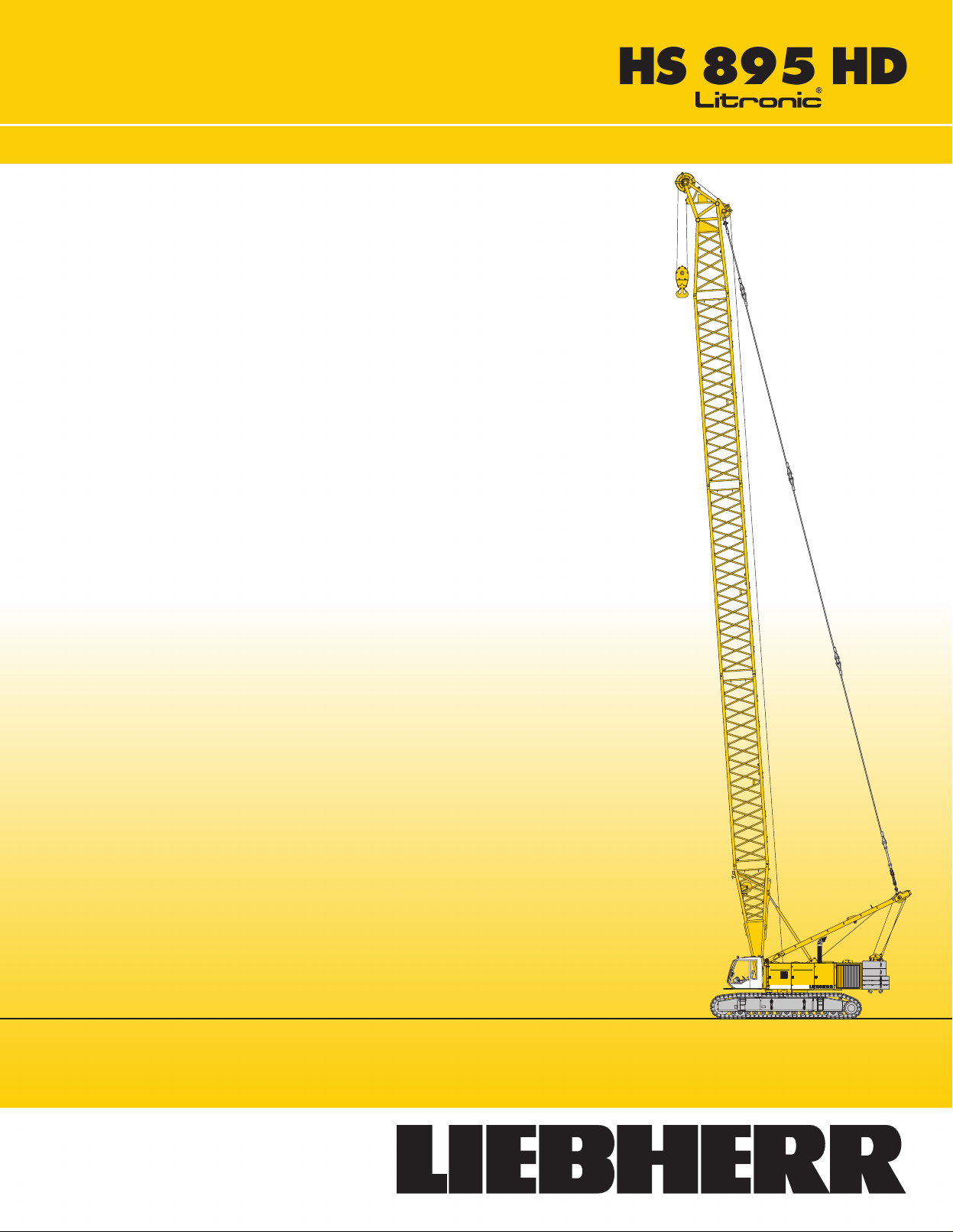
Dimensions
Basic machine with undercarriage
Operating weight
The
operating weight includes the basic machine with HD undercarriage,
2
main winches 66,200 lbs including wire ropes (492
consisting
(20 ft), 121,500 lbs basic counterweight, 43.3 inch flat track shoes and
110,200
T
otal weight
o
f A
–frame
lbs hook block.
, boom foot (23 ft), boom head (23 ft), boom section
ft) and 66 ft b
approx. 373,000 lbs
Ground pressure
Ground bearin
g p
ressur
e 13,8 P
Equipment
Main boom
Fixe
Modular designed equipment for operation as crane, with dragline or
clamshell.
For dragline operation, a rotating fairlead is fitted into the boom foot. This
minimizes
2
(No. 2
d jib
(No. 0806.xx)
the rope a
HS 895 HD
220.xx)
max. l
ngl
e t
o d
engt
rum
h
, w
hic
h r
esult
276 f
3
6 f
t – 105 f
s i
n l
owe
r rope w
ear.
oom,
Remarks
1. The liftin
2. Crane
3. The
4. Additional
SI
t
t
5. For
6. Working
7. Th
8. Calculation
9. Th
10. ANS
ponds wit
s
w
eigh
must
b
e d
value.
b
e d
educte
max. wind s
e l
iftin
and IS
O 4305 T
e s
tructure
(E
N 1
3001–2
I B 3
g c
apacitie
h c
tandin
t o
educte
e
d t
r
adi
g c
apacitie
o
0.5
ran
f the l
quipmen
i are m
f s
s are c
/ 2
s s
tate
e c
lassificatio
g o
n f
irm
, h
iftin
g d
evic
d from the g
t o
pee
tabilit
abl
004).
n boom (
d p
leas
easure
s are v
y u
nde
e 1 + 2
alculate
o get the net l
d are v
n a
orizonta
e (
ros
iftin
g c
e r
efe
d from c
ali
d for 360 d
r load i
, t
ippin
d a
ccordin
ali
d for l
ccordin
l g
round.
hoistin
s l
iftin
e.g
. boom w
apacity.
r t
o lift c
entr
s b
g a
ngl
ase
iftin
g t
o F
g r
opes
g c
apacit
har
e o
egree
d o
e 4
g t
o F
g o
.E.M
alkways
t i
n o
f s
win
s o
n DIN 1
º.
.E.M
peratio
. 1
.001
, hook b
y t
o o
perator’
g and u
f s
wing.
501
. 1
.00
n only (
, c
ran
lock
, s
hackl
btai
n a net l
, a
uxiliar
s cab o
nde
r l
9 / part 2 / c
1 – 1998
corre
s
e g
rou
p A
e e
iftin
g
y jib) must
r m
anual.
oad.
har
tc.)
t 1
1)
Page 3
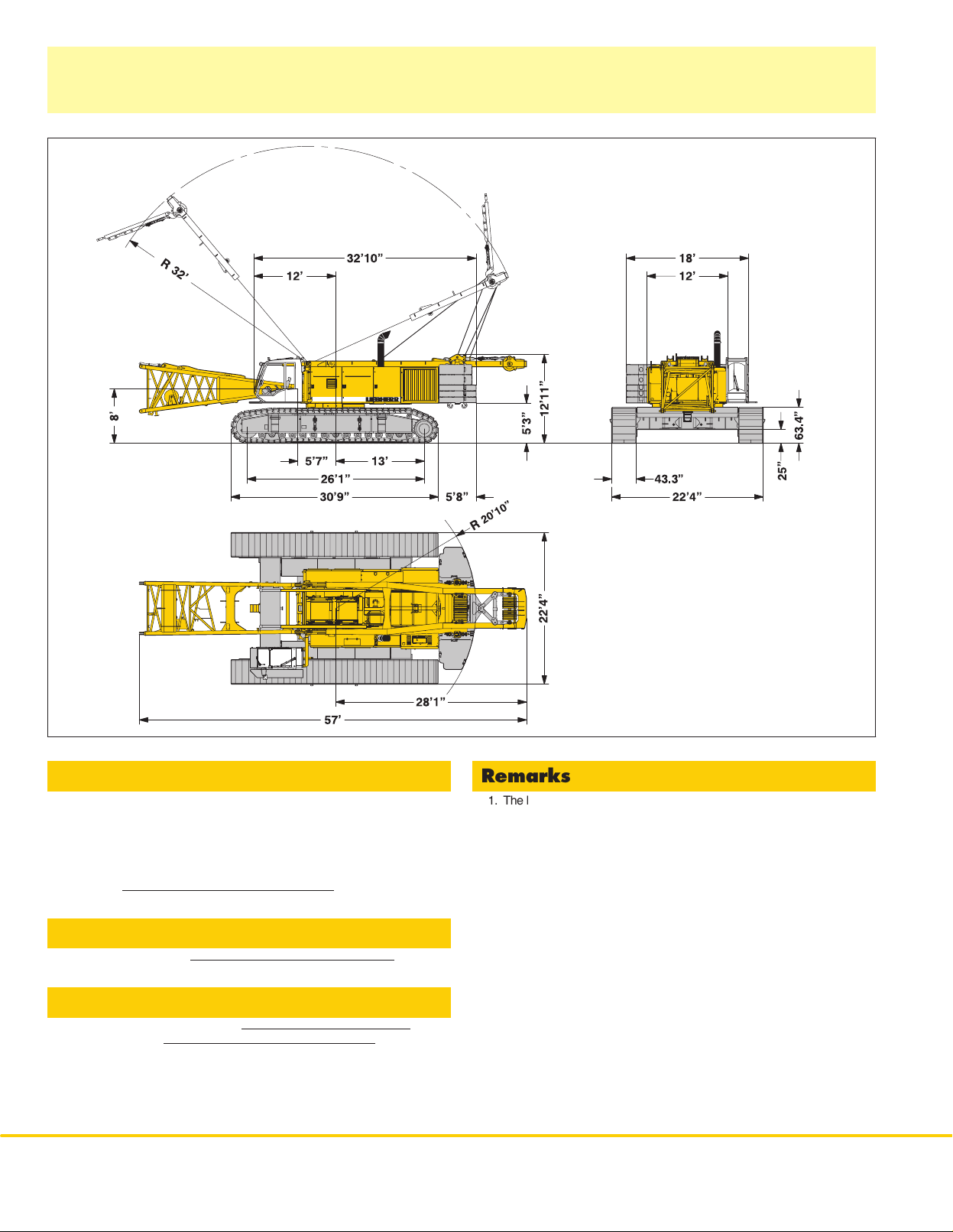
T ransport dimensions and weights
Basic machine and boom (No.
2
220.xx)
Basic machine
with A–frame, 2x 66,20
crawlers,
Width
Weight
boom f
in lbs
oot
0 l
bs winches including wire ropes (492 ft), without
, b
asi
c and c
Crawler 2x
Flat
track shoes
Width
Weight
in lbs
arbody counterweight.
1
1’6”
121,250
43.3”
47”
55,120
Boom foot (No.
Width
Weight
in lbs*
2
220.xx)
Boom section (No.
Width
Weight
in lbs*
Boom section (No.
Width
Weight
in lbs*
Boom section (No.
Width
Weight
in lbs*
12,400
2
220.xx) 10 ft
2,500
2
220.xx) 20 ft
4,150
2
220.xx) 38 ft
6,400
7’1
7’1
7’1
7’1
1”
1”
1”
1”
)
*
Including pendan
t r
opes
Boom head (No.
Width
Weight
in lbs*
2
220.xx)
H
S 895 H
7’1
1”
10,350
D3
Page 4
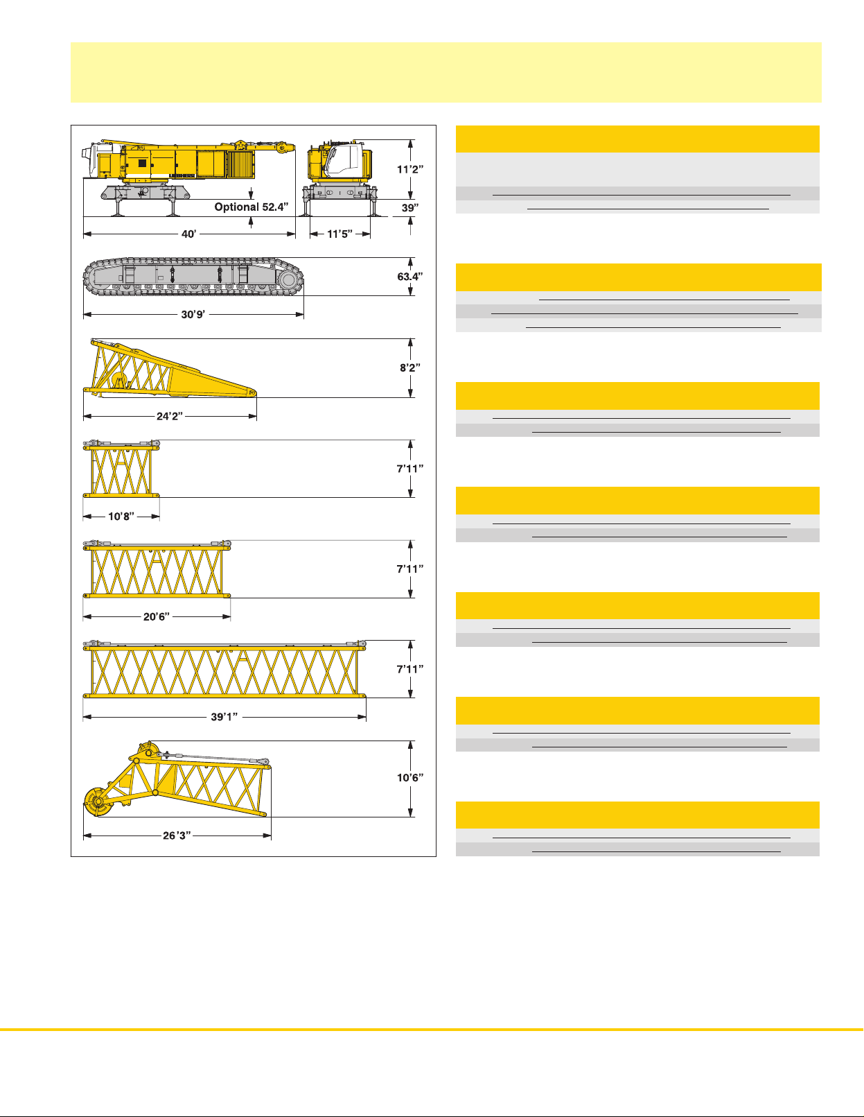
Transport dimensions
Fixed jib (No.
0
806.xx)
)
*
Including pendan
t s
traps
Counterweight
Fixed jib head (No.
Width
Weight
in lbs*
Fixed jib section (No.
Width
Weight
in lbs*
Fixed jib section (No.
Width
Weight
in lbs*
Fixed jib foot with A-frame (No.
Width
Weight
in lbs*
0
806.xx)
0
806.xx
0
806.xx
45”
980
)
)
0
806.xx)
10 ft
37”
245
20 ft
37”
430
59”
2050
Counterweight 1x
Width
W
eight in lbs
5’5”
29,300
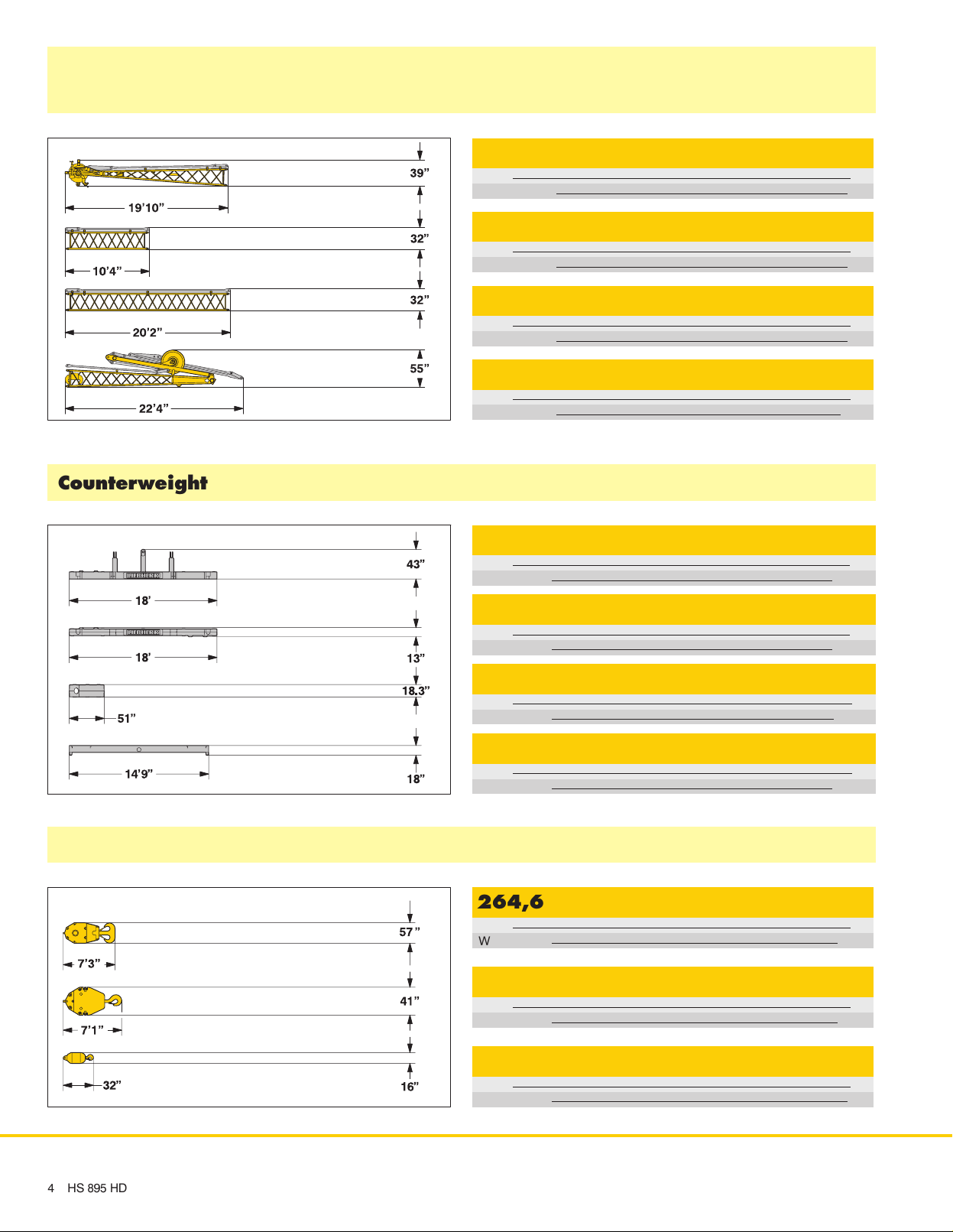
Hooks
Counterweight 2x
Width
W
eight in lbs
5’5”
23,400
Counterweight 4x optional 8x
Width
Weight
in lbs
1
55”
1,250
Carbody counterweight optional 2x
Width
Weight
in lbs
35”
29,800
264,600 lbs hook block-2sheaves
Width
Weight
in lbs
13”
3,100
132,300 lbs hook block-1sheave
Width
Weight
in lbs
12”
2,150
4HS 89
5 H
66,150 lbs single hook
Width
Weight
in lbs
D
16”
880
Page 5

Technical description
Engine
Power rating according to ISO 3046 IFN, 670 kW (898 hp) at 1900 rpm
Engine type
Fuel tank
Engine complies with NRMM exhaust certification EP
MAN D 2842 LE
264 gal capacity with continuous level indicator
and reserve warning
A / CARB T
ier 2.
Hydraulic system
The main pumps are operated by a distributor gearbox. Axial piston
displacement
needed (flow control on demand). To minimize peak pressure an
automatically
saves
pressure and return filters. Possible contamination is signaled in the cabin.
The
use of synthetic environmentally friendly oils is possible.
Ready made hydraulic retrofit kits are available to customize requirements
e.g. powering casing oscillators, VM–vibrators, hydraulic grabs, hanging
leads
W
orking pressure
Oil tank capacity
pumps work in closed and open circuits supplying oil only when
working pressure cut of
energy
. The hydraulic oil is cleaned through
etc.
max. 5076 PSI
290 gal
f is integrated. This spares pumps
electronically controlled
and
Boom winch
Line pul
l
Rop
e d
iamete
Boo
m u
r
p 137 sec. from 15º t
max. 3
2
4 m
m
3,10
0 l
bs
o 8
6º
Main winches
Winch
options:
Line pull (nom. load)
Rope diameter
Drum diameter
Rope speed (ft/min)
With change gear box (ft/min)
Rope capacity 1st layer
The winches are outstanding in their compact design and easy assembly
Clutch and braking functions on the free fall system are provided by a
compact
designed, low wear and maintenance free multi–disc brake.
The
drag and hoist winches use pressure controlled, variable flow hydraulic
motors. This system features sensors that automatically adjust oil flow to
provide
max. winch speed depending on load.
Option:
Crane winch (main winch)
Auxiliary winch
T
agline winch
33,100
15,500
15,500
6,600
lbs with multi–disc holding brake
lbs in boom foot
lbs with free fall
lbs with free fall
66,200 lbs
36 mm
32.7”
0–252
0–515
180 ft
.
Crawlers
Propulsion through axial piston motor, hydraulically released spring loaded
multi–disc
device.
Flat track shoes
Drive speed
Option:
F
F
brake, maintenance free crawler tracks,
43.3 inch
0 – 0.8 mph
2 speed hydraulic motor for higher travel speed
Self assembly system, jack up system
hydraulic chain tensioning
Swing
Consists of rollerbearing wit
fixed axial piston hydraulic motor, spring loaded and hydraulically released
multi–disc
Swing speed from 0 – 3.6 rpm continuously variable, selector for 3 speed
ranges
Standard:
Second swing drive
Optional:
Third swing drive
holding brake, planetary gearbox and pinion.
to increase swing precision.
h e
xternal teeth for lower tooth flank pressure,
Noise emission
Noise emissions correspon
equipmen
t used o
utdoors.
d with 2
000/14/E
C d
irectiv
e on n
ois
e e
missio
n b
y
Control
The
control system – developed and manufactured by Liebherr – is designed
to
withstand
common
shown on a high resolution display
control
Dragline
It is designed for power lifting of the dragline bucket without using the drag
winch
An additional option is the ”Redundant Control System”, whic
restricted
base
On
request, Liebherr also of
free
Operation:
for
winch I and II. Crawler control is actuated with the two
Additionally,
Options:
F
F
F
F
extreme temperature changes and the rough heavy duty tasks
in the construction industry
for all movements, which can be carried out simultaneously
operation: A special
brake.
operation of the machine in the event of a failure on the electronic
control or its sensors.
fers special custom designed control systems
fall winches.
Left joy stick for boom
hand levers can be attached to the pedals.
Special demolition control system
MDE: Machine data recording
PDE: Process data recording
GSM modem
. Complete machine operating data are
. The crane is equipped with proportional
”Interlock” control system is an option available.
winch and swing, right two directional levers
central foot pedals.
HS
.
h a
895 HD
llows
for
5
Page 6
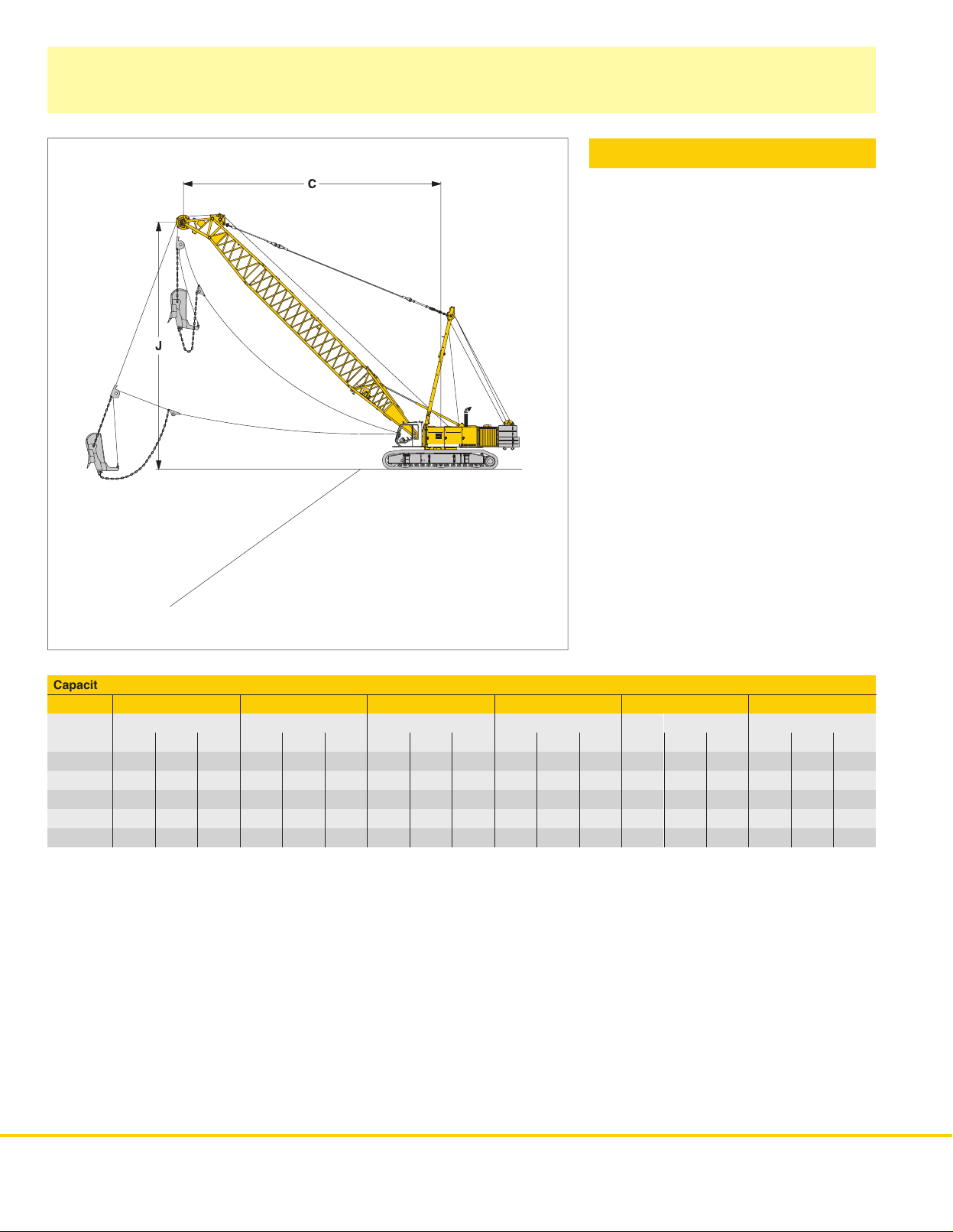
Dragline equipment
121,500 lbs counterweight
Working diagram
C =Radius / dumping radius
J =
Height of boom head sheave centre above
ground level
Capacities
Max. capacities in 1000 lbs do not exceed 75% of tipping load.
in 1000 lbs for boom lengths (84 ft – 181 ft)
84 ft
C J C J C J C J C J C J
α
45 69.2 64.6 64,4 83.0 78.7 49,4 96.1 91.9 39,9 110.2 106.0 31,5 123.4 119.1 25,6 137.1 132.9 20,3
40 73.8 59.7 58,6 88.9 72.2 44,7 103.3 84.3 35,9 118.4 96.8 28,2 132.5 108.9 22,5 147.6 121.7 17,2
35 78.1 54.1 54,2 94.2 65.3 41,2 109.6 76.1 32,6 125.7 87.3 25,6 141.1 98.1 20,3 157.2 109.3 15,0
30 81.7 48.2 50,7 98.7 57.1 38,4 114.8 67.3 30,2 131.9 77.1 23,4 149.9 86.6 18,3 165.4 96.5 13,2
25 84.9 42.0 46,9 102.6 50.2 35,7 119.7 58.1 27,6 137.5 66.3 21,2 154.5 74.1 16,1 172.2 82.7 11,5
ft ft lbs ft ft lbs ft ft lbs ft ft lbs ft ft lbs ft ft lbs
104 ft 123 ft 142 ft 161 ft 181 ft
counterweight 121,500 lbs
6
HS 895 HD
Page 7
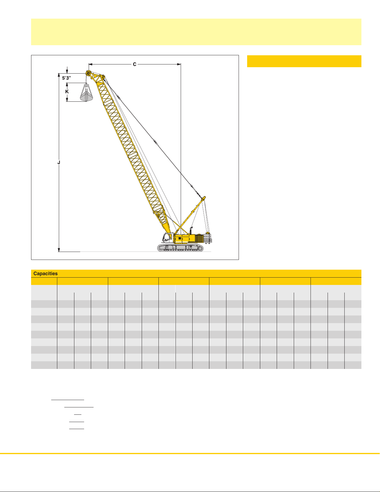
Clamshell equipment
121,500 lbs counterweight
Working diagram
C =Radius / dumping radius
J =
Height of boom head sheave centre above
ground level
K =
Length of clamshell (depending on type and
capacity of bucket)
Capacities in 1000 lbs for boom lengths (84 ft – 181 ft)
84 ft
C J C J C J C J C J C J
α
65 45.9 81.0 71,7 54.1 98.8 71,7 62.0 115.8 65,0 70.2 133.5 54,0 78.1 150.6 46,1 86.6 168.3 38,8
60 52.2 77.7 71,7 62.0 94.8 65,5 71.5 110.9 53,6 81.3 127.9 44,1 90.6 144.0 37,3 100.4 161.1 30,9
55 58.1 73.8 71,4 69.6 89.9 56,0 80.4 105.3 44,8 91.5 121.4 37,0 102.4 136.8 30,6 113.5 152.9 25,1
50 64.0 69.6 63,1 76.4 84.6 48,9 88.6 99.1 39,5 101.0 114.2 31,7 113.2 128.3 26,0 126.0 143.3 20,8
45 69.2 64.6 56,7 83.0 78.7 43,7 96.1 91.9 35,1 110.2 106.0 27,8 123.4 119.1 22,7 137.1 132.9 18,1
40 73.8 59.7 51,6 88.9 72.2 39,5 103.3 84.3 31,5 118.4 96.8 24,7 132.5 108.9 19,8 147.6 121.7 15,6
35 78.1 54.1 47,8 94.2 65.3 36,4 109.6 77.7 28,7 125.7 87.3 22,5 141.1 98.1 17,8 157.2 109.3 13,7
30 81.7 48.2 44,5 98.8 58.1 33,7 114.8 67.3 26,5 131.9 77.1 20,5 148.3 86.6 16,3 165.4 96.5 12,1
25 85.0 42.0 41,4 102.7 50.2 31,1 119.8 58.1 24,0 137.5 66.3 18,5 154.5 74.1 14,8 172.2 82.7 10,6
Max. capacities in 1000 lbs do not exceed 66.7 % of tipping load.
Load diagram restricted by safety factors of standard ropes:
Winches
Rope diameter
Calc. breaking load
1–rope clamshell
2–rope clamshell
ft ft lbs ft ft lbs ft ft lbs ft ft lbs ft ft lbs ft ft lbs
66,200
lbs
36
mm
260,550
51,800
69,000
lbf
lbs
lbs
104 ft 123 ft 142 ft 161 ft 181 ft
counterweight 121,500 lbs
HS
895 HD
7
Page 8
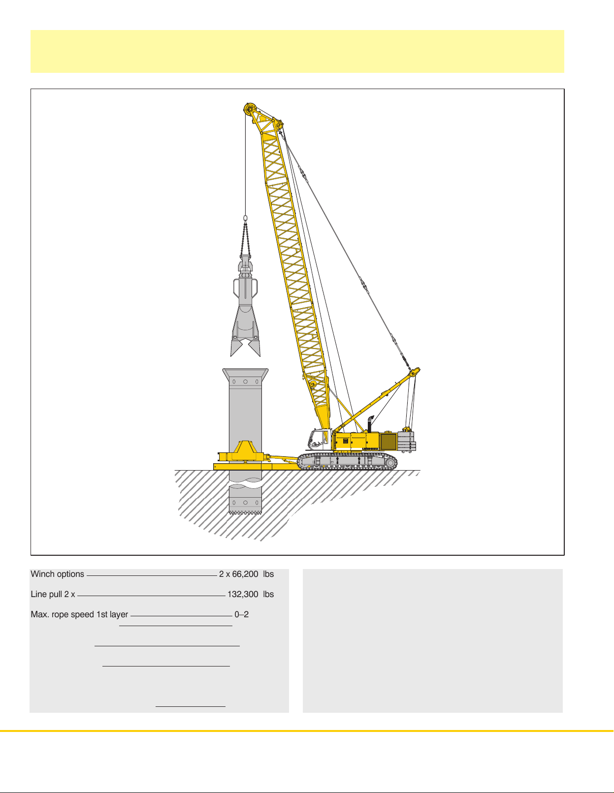
Equipment
Casing oscillator
Winc
h o
Lin
e pull 2 x
Max
. rope s
h c
hang
(wit
Drillin
g d
Max
. c
hise
Max
. c
apacit
directio
a
t 33 f
t r
8HS
895 HD
ption
s
pee
e gear box)
iamete
l w
eigh
y with boom p
n o
f u
ndercarriag
adiu
s (75% t
d 1st l
r
t
aye
r
e with 104 f
ippin
g l
ositio
oad
n in l
ongitudina
t main boom
)
l
2 x 6
1
32,300 lbs
0
0
3
1
68,900 lbs
6,200 lbs
–253 ft/min
–515 ft/min
1
0.8 ft
9,700 lbs
Free fal
brake working in an oil bath. Simultaneous working of both
winches
Hydrauli
q = 2 x 10⁶ g
P = 4350 PSI m
Mechanica
Automatic
the drilling process the engine power can be freely divided
between
l w
i
c s
inche
s a
o
c
asin
ssure
uppl
y for c
al/min.
ax.
l c
onnectio
peratio
g o
s with m
aintenanc
d t
hroug
h our h
asin
g o
n c
asin
n for one and two rope g
scillato
r and h
ydrauli
scillato
g o
scillato
oistin
e f
r
ree
g w
, s
prin
c s
ystem
r o
n u
ndercarriage.
rab
inche
g l
oade
.
s (
optional)
s a
s r
d m
ult
. D
equired.
i d
isc
uring
Page 9

Equipment
Dynamic soil compaction
Capacities in 1000 lbs for boom lengths (84 ft – 142 ft)
Radius 84 ft
(ft) lbs lbs lbs lbs
29.5 88,2 88,2 88,2 83,8
32.8 88,2 83,8 79,4 75,0
36.1 77,2 77,2 70,6 68,4
39.4 70,6 70,6 66,2 61,7
Max.
capacities in 1000 lbs do not exceed 75% of tipping load.
All
loads given are max. values and must not be exceeded. They are
with
max. inclination of 1 %. Lifting heigths must not exceed 98.4 ft.
Boom length
104 ft 123 ft 142 ft
only permitted in two rope automatic operation and are valid for work on a surface
HS
895 HD
9
Page 10
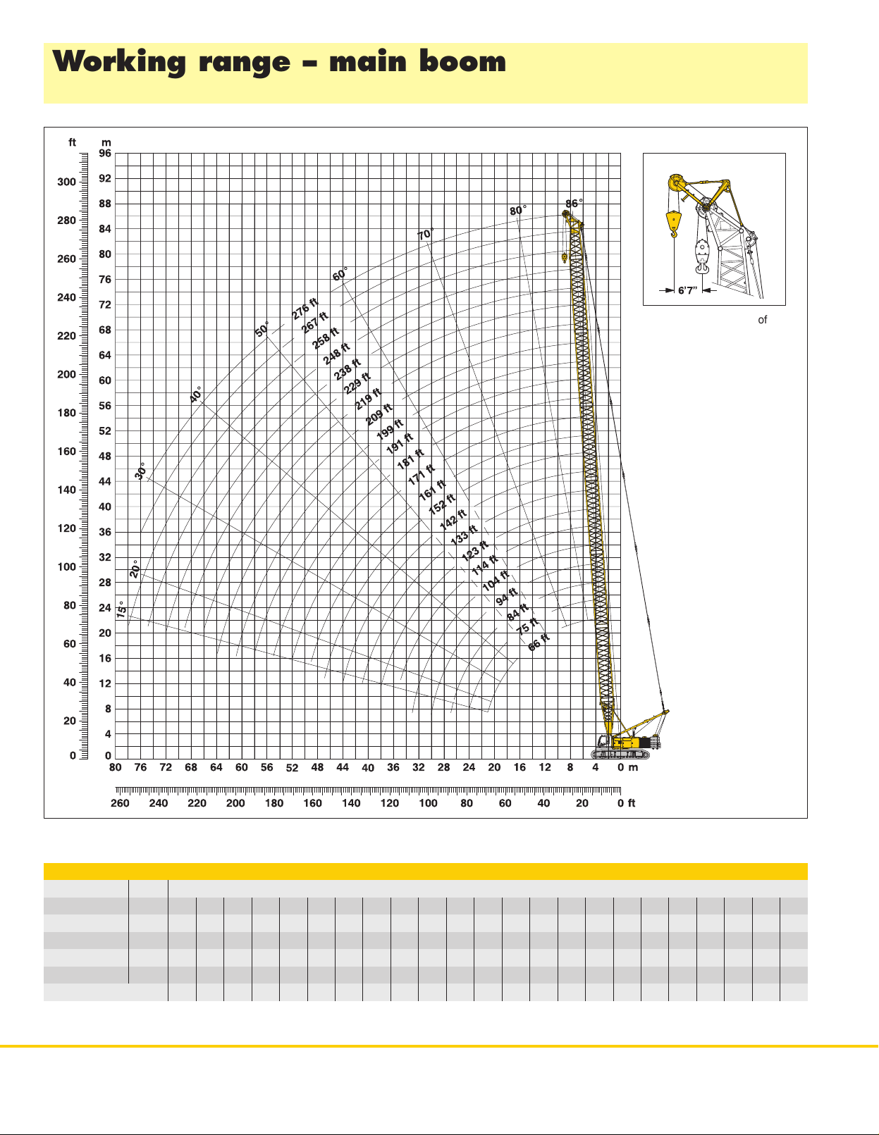
Working range - main boom (No. 2220.xx) 86° -15°
166,000 lbs counterweight and 59,500 lbs carbody counterweight
Auxiliary jib 66,200 lbs
The
maximum capacity of the
auxiliary
jib is 66,200 lbs.
The correspondin
is programmed in the LMI
system.
g load c
hart
Main boom configuration
Configuration fo
Boom foot 2
Boo
m e
xtension 1
Boo
m e
xtension 2
Boo
m e
xtension 3
Boo
m h
ead 2
Boo
m l
engt
*Actual
lengths of boom sections are metric (e.g. 3 m, 6 m, 1
10 HS
895 HD
r boom l
ength
s (66 f
t – 276 f
t)
Length Amoun
3 f
t 1 1 1 1 1 1 1 1 1 1 1 1 1 1 1 1 1 1 1 1 1 1 1
0 f
t* 1 1 1 1 1 1 1 1 1 1 1
0 f
t* 1 1 1 1 1 1 1 1 1 1 1 1
8 f
t* 1 1 1 1 2 2 2 2 3 3 3 3 4 4 4 4 5 5 5 5 6
3 f
t 1 1 1 1 1 1 1 1 1 1 1 1 1 1 1 1 1 1 1 1 1 1 1
h i
n (
ft) 66 75 84 94 104 11 4 123 133 142 152 161 171 181 191 199 209 219 229 238 248 258 267 276
(table
1 – No. 2
220.xx)
t of boom e
1.7 m). The figures shown above are approximate conversions to feet.
xtensions
Page 11

Lift chart for main boom (No. 2220.xx)
143,500 lbs counterweight and 59,500 lbs carbody counterweight
Capacities
Counterweight 143,500 lbs and 59,500 lbs carbody counterweight
Radius 66 84 104 123 142 161 181 199 219 238 258 267 Radius
in 1000 lbs for boom lengths (66 ft – 267 ft) – with 66,200 lbs winches
Boom length in (ft)
(ft) lbs lbs lbs lbs lbs lbs lbs lbs lbs lbs lbs lbs (ft)
16 *440,9 16
20 *440,9 *424,6 *432,2 20
25 *338,3 *339,2 *339,5 *313,3 *321,2 25
30 252.6 253.2 253.3 253.3 252.3 244.5 220.4 181.3 30
35 200.7 201.2 201.0 200.9 200.5 200.2 197.3 168.4 144.9 120.0 35
40 165.8 166.3 166.0 165.8 165.3 164.9 164.3 155.1 133.7 114.0 111.0 100.8 40
45 140.8 141.2 140.9 140.6 140.0 139.5 138.9 138.3 124.0 105.9 106.1 94.6 45
50 121.9 122.4 121.9 121.6 121.0 120.4 119.7 119.1 116.7 95.7 101.9 90.7 50
55 107.1 107.6 107.2 106.8 106.1 105.6 104.8 104.1 103.3 91.6 96.8 87.5 55
60 95.2 95.8 95.3 95.0 94.2 93.6 92.8 92.1 91.3 87.6 89.7 85.0 60
65 85.3 86.0 85.6 85.3 84.5 83.9 83.0 82.3 81.4 80.7 79.8 79.3 65
85 59.6 59.5 59.2 58.4 57.7 56.8 56.0 55.0 54.2 53.2 52.7 85
105 44.2 44.1 43.3 42.7 41.7 41.0 40.0 39.1 38.1 37.6 105
120 36.0 35.4 34.8 33.8 33.1 32.0 31.2 30.1 29.6 120
140 27.5 27.0 26.1 25.3 24.3 23.4 22.4 21.8 140
160 21.1 20.3 19.6 18.6 17.7 16.6 16.1 160
180 15.7 15.1 14.1 13.3 12.2 11.6 180
200 11.4 10.6 9.8 8.7 8.1 200
215 8.3 7.5 6.5 5.9 215
235 4.9 4.0 3.4 235
245 2.8 2.3 245
250 2.3 250
Above lift chart is for reference only
*) Only with special boom head
. For actual lift duty please refer to lift chart in operator’s cab or manual.
HS 895 HD
11
Page 12

Lift chart for main boom (No. 2220.xx)
166,000 lbs counterweight and 59,500 lbs carbody counterweight
Capacities in 1000 lbs for boom lengths (66 ft – 276 ft) – with 66,200 lbs winches
Counterweight 166,000 lbs and 59,500 lbs carbody counterweight
Boom length in (ft)
Radius 66 84 104 123 142 161 181 199 219 238 258 276 Radius
(ft) lbs lbs lbs lbs lbs lbs lbs lbs lbs lbs lbs lbs (ft)
25 *369,3 *360,2 *349,2 *322,9 25
30 275.3 275.9 275.7 275.9 *275,2 244.5 220.4 181.3 30
35 218.9 219.4 219.2 219.1 218.7 218.4 201.2 168.4 144.9 120.0 35
40 181.0 181.5 181.2 181.0 180.5 180.0 179.5 155.1 133.7 114.0 111.0 89.3 40
45 153.8 154.3 153.9 153.6 153.0 152.5 151.9 142.9 124.0 105.9 106.1 85.6 45
50 133.3 133.8 133.4 133.0 132.4 131.9 131.1 130.5 116.7 95.7 101.9 82.5 50
55 117.3 117.8 117.4 117.0 116.3 115.7 115.0 114.3 109.9 91.6 96.8 79.9 55
60 104.3 104.9 104.5 104.1 103.4 102.8 102.0 101.3 100.5 87.6 93.1 77.7 60
65 93.6 94.4 94.0 93.6 92.8 92.2 91.3 90.6 89.8 84.1 87.8 74.6 65
85 65.7 65.6 65.3 64.5 63.8 62.9 62.1 61.2 60.3 59.4 58.5 85
105 49.0 48.9 48.1 47.5 46.6 45.8 44.8 44.0 42.9 42.1 105
120 40.2 39.6 39.0 38.0 37.2 36.2 35.4 34.3 33.4 120
140 31.0 30.5 29.6 28.8 27.8 27.0 25.9 25.0 140
160 24.2 23.4 22.6 21.6 20.8 19.7 18.8 160
180 18.4 17.8 16.8 16.0 14.9 14.0 180
200 13.9 13.0 12.2 11.1 10.2 200
215 10.5 9.8 8.7 7.8 215
235 7.0 6.0 5.1 235
255 3.6 2.8 255
260 2.3 260
Above lift chart is for reference only
*) Only with special boom head
. For actual lift duty please refer to lift chart in operator’s cab or manual.
12 HS
895 HD
Page 13
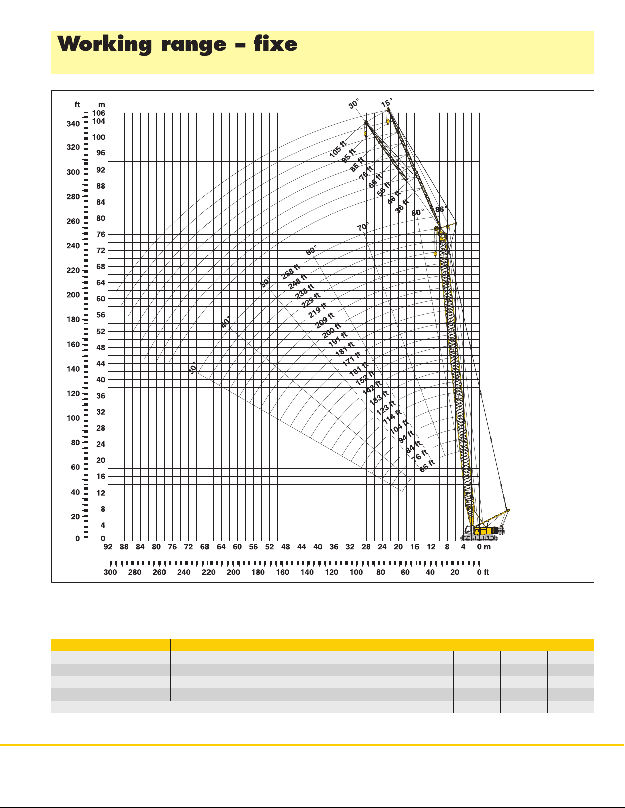
Working range - fixed jib (No. 0806.xx) 15° and 30°
Main boom 86° -30°
Boom configuration for boom lengths (66 ft - 258 ft) – se
e t
abl
e 1 o
n page 1
Fixed jib configuration for fixed jib lengths (36 ft - 105 ft)
Length Amount
Fixed jib foot
Fixed jib insert
Fixed jib insert
Fixed jib head
Fixed jib length in (ft)
*Actual lengths of boom sections are metric (e.g. 3 m, 6 m,). The figures shown above are approximate conversions to feet.
18 ft
10 ft*
20 ft*
18 ft
1 1 1 1 1 1 1 1
1 1 1 1
1 1 2 2 3 3
1 1 1 1 1 1 1 1
36 46 56 66 76 85 95 105
of fixed jib extensions
0
HS
895 HD
13
Page 14

Lift chart - fixed jib (No. 0806.xx)
Offset 15°
Main boom 66 ft
Fixed
jib length in (ft)
36 66 85 105
Radius (ft)
30 54.3
45 42.3 23.4
50 40.7 22.3 15.6
60 38.4 20.9 12.8 10.0
70 36.6 19.9 11.8 8.6
80 35.3 18.9 11.1 8.2
90 34.4 18.2 10.3 7.9
95 34.0 17.8 10.0 7.8
110 16.8 9.2 7.3
120 16.0 8.7 7.1
140 8.1 6.7
160 6.7
lbs lbs lbs lbs
Main boom 152 ft
Fixed
jib length in (ft)
36 66 85 105
Radius (ft)
38 50.8
55 42.0 22.6
65 40.7 21.9 13.3
75 39.8 21.1 12.8 8.8
80 39.1 20.7 12.5 8.7
100 37.1 19.6 11.4 8.2
120 35.5 18.5 10.5 7.7
140 31.3 17.7 9.7 7.3
170 22.4 16.7 8.8 6.9
200 15.3 8.2 6.6
215 8.0 6.5
235 6.5
lbs lbs lbs lbs
Main boom 94 ft
Fixed
jib length in (ft)
36 66 85 105
Radius (ft)
29.9 55.5
45 44.1 26.2
55 41.1 22.3 13.6
65 39.3 21.1 12.8 9.0
70 38.5 20.6 12.4 8.8
80 37.2 19.8 11.6 8.4
90 35.9 19.0 11.0 8.1
100 35.0 18.5 10.4 7.8
120 33.8 17.3 9.4 7.3
150 15.4 8.4 6.8
170 7.9 6.6
190 6.6
lbs lbs lbs lbs
Main boom 181 ft
Fixed
jib length in (ft)
36 66 85 105
Radius (ft)
41.9 48.6
60 41.3 22.0
70 40.1 21.4 13.2
80 39.3 20.8 12.8 8.8
100 37.5 19.7 11.8 8.3
120 36.1 18.7 11.0 7.9
140 29.9 18.0 10.1 7.5
160 23.7 17.3 9.5 7.2
195 15.9 16.2 8.6 6.8
225 12.8 8.1 6.5
245 7.9 6.5
260 6.5
lbs lbs lbs lbs
Main boom 123 ft
Fixed
jib length in (ft)
36 66 85 105
Radius (ft)
33.9 53.1
50 43.2 23.2
60 41.3 22.1 13.4
70 39.8 21.2 12.8 8.9
80 38.4 20.4 12.1 8.6
90 37.5 19.7 11.5 8.3
100 36.4 19.0 11.0 8.0
120 34.8 18.0 10.0 7.5
140 32.8 17.2 9.2 7.2
170 15.6 8.4 6.8
190 8.0 6.6
210 6.6
lbs lbs lbs lbs
Main boom 209 ft
Fixed
jib length in (ft)
36 66 85 105
Radius (ft)
45.9 45.7
65 39.9 21.4
70 39.4 21.1 15.1
80 38.5 20.8 12.8 9.7
100 37.1 19.7 12.0 8.4
120 35.6 18.9 11.2 8.0
140 28.4 18.1 10.5 7.6
180 17.4 16.9 9.3 7.0
215 11.1 13.0 8.6 6.7
245 8.9 8.1 6.5
265 7.6 6.4
285 6.4
lbs lbs lbs lbs
Main boom 229 ft
Fixed
jib length in (ft)
36 66 85 105
Radius (ft)
48.6 43.6
65 39.0 21.1
75 38.1 20.7 13.1
85 37.3 20.4 12.6 8.8
100 36.4 19.6 12.1 8.4
120 35.1 18.9 11.3 8.0
160 21.1 17.5 10.0 7.4
200 12.4 14.3 9.1 6.9
235 7.2 9.1 8.4 6.6
265 5.6 6.6 6.4
285 4.6 5.5
305 3.8
Capacities in 1000 lbs with fixed jib (No. 0806.xx) 166,000 lbs counterweight + 59,500 lbs carbody counterweight. Above lift chart is for reference only
For actual lift duty please refer to lift chart in operator’s cab or manual.
14 HS
895 HD
lbs lbs lbs lbs
Main boom 248 ft
Fixed
jib length in (ft)
36 66 85 105
Radius (ft)
51.3 41.3
70 37.3 20.4
80 36.5 20.1 12.8
85 36.1 19.9 12.6 9.6
120 33.3 18.7 11.4 8.1
160 20.1 17.4 10.2 7.4
200 11.5 13.4 9.2 6.9
240 5.7 7.5 8.4 6.6
250 4.6 6.3 7.4 6.5
280 3.2 4.2 5.2
300 2.5 3.4
310 2.5
lbs lbs lbs lbs
Main boom 258 ft
Fixed
jib length in (ft)
36 46 56
Radius (ft)
52.6 40.4
60 37.3 30.7
65 36.9 30.4 24.7
80 36.0 29.7 24.1
100 34.7 28.6 23.3
120 32.5 27.8 22.6
160 19.6 20.4 21.1
200 10.9 11.6 12.3
240 5.2 5.8 6.4
260 2.9 3.5 4.2
270 2.5 3.1
275 2.7
lbs lbs lbs
.
Page 15

Lift chart - fixed jib (No. 0806.xx)
Offset 30°
Main boom 66 ft
Fixed
jib length in (ft)
36 66 85 105
Radius (ft)
40 38.6
60 33.3 18.7
70 31.4 17.4 11.8
85 28.0 15.7 9.4 7.5
90 27.3 15.3 9.2 7.4
95 26.6 14.9 9.0 7.3
120 13.4 8.1 6.9
125 13.3 8.0 6.8
140 7.8 6.6
145 7.8 6.6
160 6.5
165 6.5
lbs lbs lbs lbs
Main boom 152 ft
Fixed
jib length in (ft)
36 66 85 105
Radius (ft)
46.9 40.0
70 34.7 18.6
85 33.6 17.9 10.1
100 31.8 16.7 9.6 7.4
110 31.0 16.2 9.3 7.3
120 29.7 15.5 9.0 7.2
140 27.6 14.6 8.5 7.0
160 25.3 13.9 8.2 6.8
170 22.6 13.6 8.0 6.7
200 13.2 7.8 6.5
220 7.8 6.4
240 6.4
lbs lbs lbs lbs
Main boom 94 ft
Fixed
jib length in (ft)
36 66 85 105
Radius (ft)
38.8 41.8
60 34.8 21.3
75 32.4 17.6 10.2
90 29.9 16.2 9.5 7.5
95 29.0 15.8 9.3 7.4
100 28.3 15.4 9.1 7.3
105 27.6 15.0 9.0 7.2
110 27.1 14.8 8.8 7.1
120 26.2 14.2 8.4 7.0
150 13.2 7.9 6.7
170 7.8 6.5
190 6.4
lbs lbs lbs lbs
Main boom 181 ft
Fixed
jib length in (ft)
36 66 85 105
Radius (ft)
50.8 38.8
75 34.5 18.5
90 33.6 17.9 10.1
100 32.7 17.2 9.8 8.3
120 31.1 16.1 9.2 7.3
140 29.1 15.1 8.8 7.0
160 24.2 14.4 8.4 6.9
180 19.2 13.8 8.1 6.7
195 16.1 13.5 7.9 6.6
225 13.1 7.8 6.4
245 7.8 6.4
265 6.4
lbs lbs lbs lbs
Main boom 123 ft
Fixed
jib length in (ft)
36 66 85 105
Radius (ft)
42.7 41.0
65 34.8 18.8
80 33.1 17.8 10.2
100 30.6 16.2 9.4 7.4
110 29.0 15.5 9.1 7.3
120 27.8 14.9 8.8 7.1
130 26.9 14.5 8.5 7.0
140 26.2 14.0 8.3 6.9
145 25.8 13.8 8.2 6.8
175 13.2 7.8 6.6
195 7.8 6.4
215 6.4
lbs lbs lbs lbs
Main boom 209 ft
Fixed
jib length in (ft)
36 66 85 105
Radius (ft)
56.2 37.5
80 33.8 18.3
95 32.9 17.8 10.1
105 32.5 17.3 9.8 8.2
120 31.6 16.6 9.4 7.3
140 28.8 15.7 9.0 7.1
160 22.4 14.9 8.6 6.9
200 13.4 13.8 8.1 6.7
225 9.4 11.5 7.8 6.5
255 7.5 7.7 6.4
275 6.4 6.3
295 5.4
lbs lbs lbs lbs
Main boom 229 ft
Fixed
jib length in (ft)
36 66 85 105
Radius (ft)
57.5 37.0
80 33.4 18.1
95 32.6 17.7 10.1
110 32.0 17.1 9.7 7.4
120 31.5 16.6 9.5 7.3
140 28.3 15.9 9.0 7.1
160 21.8 15.0 8.7 6.9
200 12.9 13.9 8.1 6.6
235 7.5 9.6 7.8 6.5
265 5.8 7.1 6.3
285 4.9 6.0
305 4.0
Capacities in 1000 lbs with fixed jib (No. 0806.xx) 166,000 lbs counterweight + 59,500 lbs carbody counterweight. Above lift chart is for reference only
For actual lift duty please refer to lift chart in operator’s cab or manual.
lbs lbs lbs lbs
Main boom 248 ft
Fixed
jib length in (ft)
36 66 85 105
Radius (ft)
60.1 36.0
85 32.5 17.8
95 32.0 17.6 11.5
110 31.3 17.1 9.7 7.4
120 30.8 16.7 9.5 7.3
140 27.5 16.0 9.1 7.1
180 16.0 14.6 8.4 6.8
220 8.7 11.0 8.0 6.5
255 4.2 6.2 7.5 6.4
285 2.9 4.2 5.3
305 2.2 3.4
315 2.5
lbs lbs lbs lbs
Main boom 258 ft
Fixed
jib length in (ft)
36 46 56
Radius (ft)
61.5 35.6
70 32.8 26.5
80 32.4 26.1 21.4
100 31.5 25.4 20.9
120 30.7 24.8 20.1
140 27.0 23.8 19.5
160 20.5 21.5 18.4
200 11.5 12.3 13.2
240 5.5 6.2 7.0
265 2.6 3.3 4.0
275 2.2 2.9
280 2.4
lbs lbs lbs
HS
895 HD
.
15
Page 16
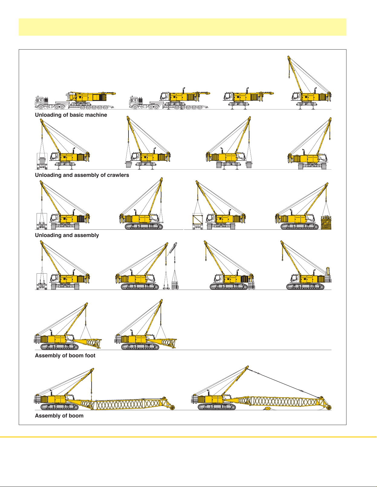
Self assembly system
Unloading
Unloading and assembly of crawlers
Unloading and assembly of carbody counterweight (option)
of basic machine
Unloading and assembly of boom
Unloading and assembly of counterweight
Assembly of boom foot
Assembly of boom
Liebherr-Werk Nenzing GmbH
P.O. Box 10, A-6710 Nenzing/Austria
Tel.: +43 50809 41 - 473
Fax: +43 50809 41 - 499
crawler.crane@liebherr.com
www.liebherr.com
Reeving of hoist ropes
895 HD – 10223036 – 02/2008 Subject to change without notice.
HS
 Loading...