

Page 1
Technical data
Hydraulic crawler crane
Complies with ANSI B 30.5
HS 885 HD
Page 2
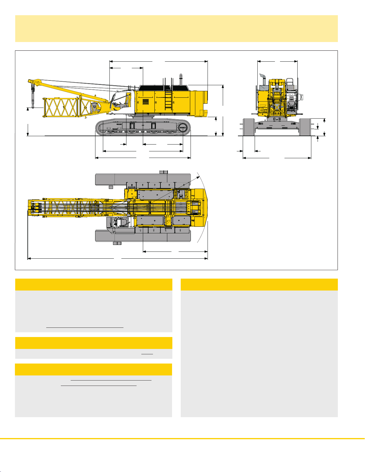
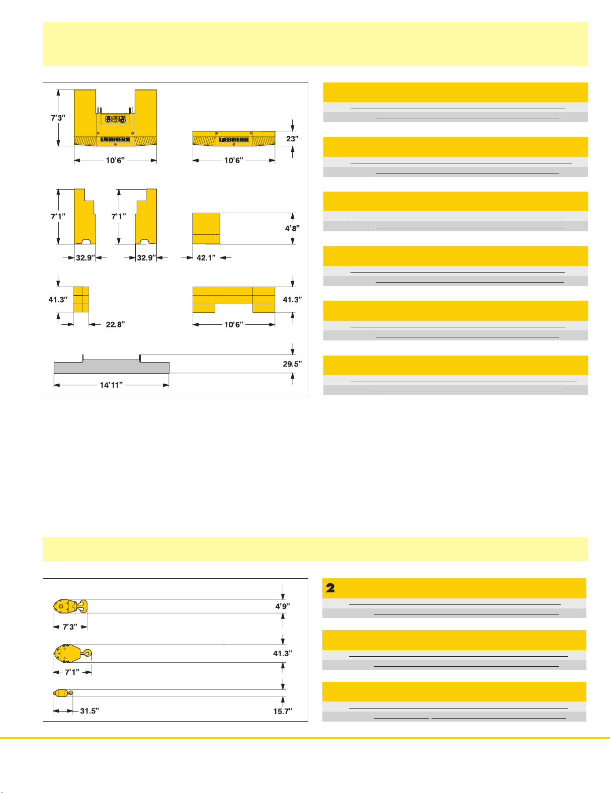
Dimensions
4´7´´
11´1´´
26´5´´
22´2´´
14´1´´
5´2´´
7´9´´
27´2´´
9´3´´
R 18´2´´
50´
17´
39.4´´
18´10´´
21.6´´
56´´
11´
Basic machine with undercarriage
Operating weight
The operating weight includes the basic machine with HD undercarriage,
2 main winches 66,200 lbs with speed change gear and 36 f t boom,
consisting of A–frame, boom foot (13 ft), boom head section (21 ft),
boom head (2 ft) and 53,200 lbs basic counterweight, 33,900 lbs add.
counter weight and 15,400 lbs carbody counterweight.
Total weight approx. 296,700 lbs
Ground pressure
Ground bearing pressure over side, on compact ground 24 psi
Equipment
Main boom max. length 184 f t
Fixed jib (N o. 080 6.xx) 36 ft – 105 f t
Universal boom head with interchangeable rope pulleys.
Modular designed equipment for operation as crane, with dragline or
clamshell. For dragline operation, a rotating fairlead is fitted into the
boom foot. This minimizes the rope angle to drum, which results in
lower rope wear.
Remarks
The lifting capacities stated are valid for lifting operation only
1.
(corresponds with crane classification according to F.E.M. 1.001,
crane group A1)
Crane standing on firm, horizontal ground.
2.
The weight of the lifting device (hoisting ropes, hook block, shackle
3.
etc.)must be deducted from the gross lifting capacity to obtain
a net lifting value.
Additional equipment on boom (e.g. boom walkways, auxiliary jib)
4.
must be deducted to get the net lifting capacity.
For max. wind speed please refer to lift chart in operator’s cab or
5.
manual.
Working radii are measured from centre of swing and under load.
6.
The lifting capacities are valid for 360 degrees of swing.
7.
The structures are calculated according to F.E.M. 1.001 – 1998
8.
(EN 13001–2/ 2004).
ANSI B 30.5
9.
2 HS 885 HD
Page 3
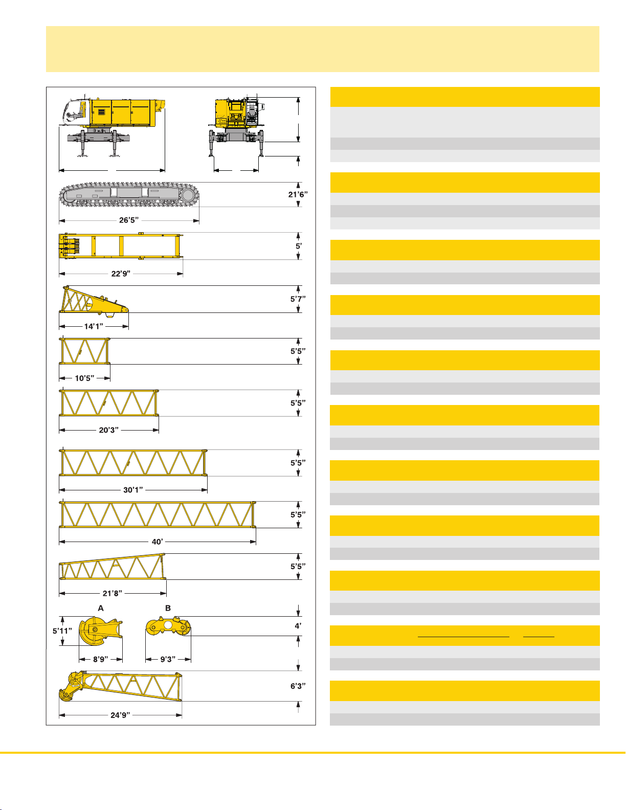
Transport dimensions and weights
27´
45.3´´
11´1´´
12´
Basic machine and boom
Basic machine
with HD undercarriage, V12- Mercedes Benz diesel engine, 2x66,200 lbs
winches with change gear box, without counterweight, coom foot and
A–frame
Width 16´2´´
Weight 96,700 lbs
Crawler
Double grouser track shoes 39.4´´
Width 41.7´´
Weight 41,300 lbs
A–frame
Width 24´´
Weight 4,850 lbs
Boom foot
Width 5´5´´
Weight* 4,600 lbs
Boom section 10 ft
Width 5´5´´
Weight* 1,700 lbs
Boom section 20 ft
Width 5´5´´
Weight* 2,750 lbs
Boom section 30 ft
Width 5´5´´
Weight* 3,700 lbs
Boom section 40 ft
Width 5´5´´
Weight* 4,700 lbs
Boom head section 21 ft
Width 9´9´´
Weight* 11,900 lbs
Boom head B A
Width 30.7´´ 42.1´´
Weight* 3,300 4,000 lbs
*) Including pendant ropes
L–boom head
Width 5´5´´
Weight* 2,600 lbs
HS 885 HD 3
Page 4
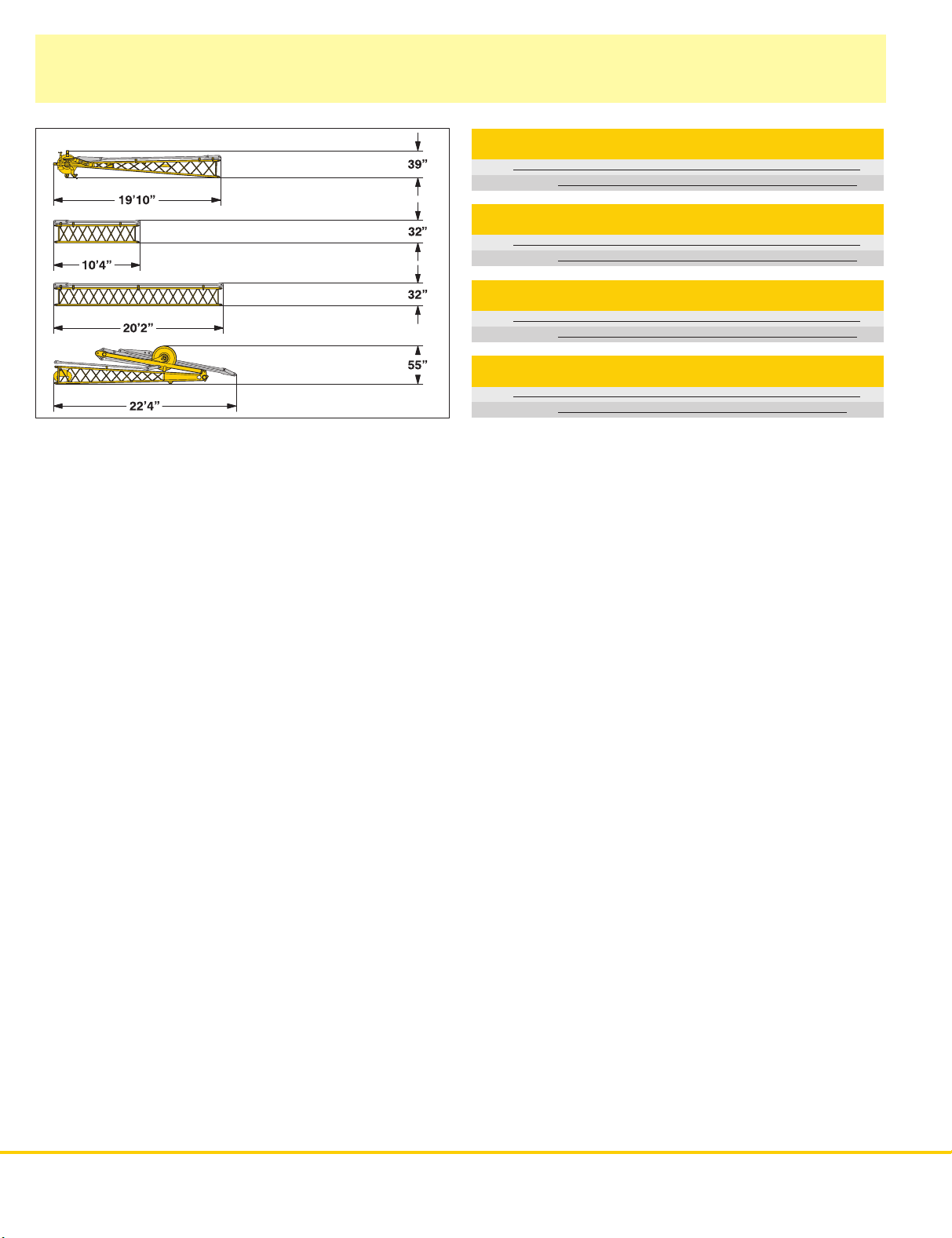
Transport dimensions and weights
Fixed jib (No.
0806.xx)
)
*
Including pendan
t s
traps
Fixed jib head (No.
Width
Weight
in lbs*
Fixed jib section (No.
Width
Weight
in lbs*
Fixed jib section (No.
Width
Weight
in lbs*
0
806.xx)
0
806.xx
0
806.xx
)
)
Fixed jib foot with A-frame (No.
Width
Weight
in lbs*
0
806.xx)
45”
980
10 ft
37”
245
20 ft
37”
430
59”
2,050
4HS
885 HD
Page 5
Transport dimensions and weights
Counterweight
Add.
counterweight II
Carbody counterweight
Basic counterweight
Add.
counterweight
Add.
counterweight
Add.
counterweight IV
III
Basic counterweight 1x
Width
Weight
in lbs
28.3”
43,200
Add. counterweight 1x
Width
Weight
in lbs
26”
10,000
Add. counterweight II 2x
Width
Weight
in lbs
13.4”
5,725
Add. counterweight III 1x
Width
Weight
in lbs
14.8”
7,050
Add. counterweight IV 1x
Width
Weight
in lbs
22.8”
15,400
Carbody counterweight 2x
Width
Weight
in lbs
7,700
8”
Hooks
264,600 lbs hook block-2sheaves
Width
Weight
in lbs
12.6”
3,100
132,300 lbs hook block-1sheave
Width
Weight
in lbs
12”
2,150
66,150 lbs single hook
Width
Weight
in lbs
HS 885 HD
16”
880
5
Page 6

Dragline equipment
71,700 lbs counterweight
Working diagram
C =Radius / dumping radius
J =
Height of boom head sheave centre
above ground level
Capacities
Max. capacities in metric tons do not exceed 75% of tipping load.
in 1000 lbs for boom lengths (59 ft – 108 ft)
59 ft 69 ft 79 ft 89 ft 98 ft
C J C J C J C J C J C J
α
45 48.2 48.9 46,3 55.4 55.8 36,8 62.3 62.6 29,5 69.2 69.9 24,7 76.4 76.8 20,7 83.0 84.0 18,7
40 51.8 44.9 40,1 59.4 51.5 30,8 66.9 57.7 25,1 74.5 64.0 21,2 82.0 70.2 17,9 89.6 76.8 16,8
35 55.1 41.0 33,5 63.0 49.9 26,5 71.2 52.1 22,6 79.1 57.7 19,0 87.3 63.6 15,9 95.5 69.6 15,0
30 57.7 36.7 29,3 66.3 41.7 24,0 74.8 46.6 19,8 83.3 51.5 16,5 91.9 56.4 13,9 100.4 61.4 13,7
25 60.0 32.2 26,2 68.9 36.0 21,4 78.0 40.4 18,1 86.9 44.6 15,0 95.8 48.6 12,6 104.7 53.1 12,3
ft lbs lbs ft ft lbs ft ft lbs ft ft lbs ft ft lbs ft ft t
counterweight 71,700 lbs
108 ft
6
HS 885 HD
Page 7

Clamshell equipment
71,700 lbs counterweight
Working diagram
C =Radius / dumping radius
J =
Height of boom head sheave centre
above ground level
K =
Length of clamshell (depending on type
and capacity of bucket)
Capacities in 1000 lbs for boom lengths (59 ft – 108 ft)
59 ft 69 ft 79 ft 89 ft 98 ft
C J C J C J C J C J C J
α
65 31.5 60.7 66,1 35.8 69.6 62,2 40.0 78.4 52,9 43.9 87.2 45,8 48.2 96.1 39,9 52.4 105.3 35,1
60 36.0 58.0 61,3 41.0 66.6 51,1 45.9 75.1 43,7 50.8 83.7 37,5 55.8 92.2 32,4 60.7 101.0 28,2
55 40.7 55.4 52,5 46.3 63.6 43,6 51.8 71.5 37,0 57.4 79.7 31,5 63.0 87.6 27,3 68.9 96.1 23,6
50 44.6 52.1 46,1 50.8 59.7 38,1 57.0 67.3 32,2 63.6 74.8 27,3 69.9 82.3 23,4 76.1 90.2 20,0
45 48.2 48.9 41,2 55.4 55.8 34,2 62.3 62.7 28,7 69.2 69.9 24,0 76.1 76.8 20,5 83.0 82.7 17,4
40 51.8 44.9 37,5 59.4 51.5 30,2 66.9 57.7 25,1 74.4 64.0 21,2 82.0 70.2 17,6 89.6 76.8 17,8
35 55.1 41.0 33,1 63.0 46.6 26,7 71.2 52.1 22,3 79.1 58.7 18,7 87.2 63.6 15,6 95.5 69.6 13,2
30 57.7 36.7 29,3 66.3 41.7 24,0 74.8 46.6 19,8 83.3 51.5 16,7 91.8 56.4 13,9 100.4 61.3 11,5
25 60.0 32.1 26,2 68.9 36.0 21,4 78.0 40.4 17,6 86.9 44.6 14,8 95.8 48.6 12,1 104.7 53.1 9,9
Max. capacities in metric tons do not exceed 66.7 % of tipping load.
Load diagram restricted by safety factors of standard ropes:
Winches
Rope diameter
Calc. breaking load
1–rope clamshell
2–rope clamshell
ft ft lbs ft ft lbs ft ft lbs ft ft lbs ft ft lbs ft ft lbs
44,100 lbs 55,200 lbs
30 mm 34 mm 36 mm
181,000 lbf 232,000 lbf
36,400 lbs 46,300 lbs
48,500 lbs 61,700 lbs
66,200 lbs
261,000 lbf
51,800 lbs
69,000 lbs
counterweight 71,700 lbs
108 ft
HS
885 HD
7
Page 8

Equipment
Casing oscillator and slurry wall grab
Casing oscillator
Winch options
Lin
e s
Lin
e s
Drillin
g d
Maximu
tw
o rope o
8
HS 885 HD
pee
d 1st gear (
pee
d 2nd gear (
iamete
m a
llowabl
peratio
ft/min
ft/min
r
e w
eigh
n 5
Slurry wall grab
2 x 5
5,20
0 lbs
2 x 6
6,20
0 l
bs
)
)
t i
n
0
0
6,20
–22
–40
8’3”
0 lbs
6
3
7
1,70
0
0
–180
–390
9
’10”
0 l
bs
Winch options
Lin
e s
pee
d 1st gear (
Lin
e s
pee
d 2nd gear (
Max
. c
hise
l w
Maximu
m a
llowabl
tw
o rope o
peratio
ft/min
)
ft/min
)
eigh
t
e w
eigh
t i
n
n 5
2 x 5
5,20
6,20
0
0
0 lbs
–22
–40
2
0 t
0 lbs
2 x 6
6,20
0 l
bs
6
3
7
1,70
0
0
–180
–390
2
5 t
0 l
bs
Page 9

Equipment
Dynamic soil compaction
Capacities in metric tons for boom lengths (69 ft – 108 ft)
Boom length
Radius
(ft) lbs lbs lbs lbs lbs
26.2 66,200 66,200 55,200 55,200 55,200
29.5 44,100 44,100 44,100 44,100 44,100
Max.
capacities in metric tons do not exceed 75% of tipping load.
All loads given are max. values and must not be exceeded. They are only permitted in two rope automatic operation and are valid for work on a surface with
max. inclination of 1 %. Lifting heigths shall not exceed 82 ft.
69 ft 79 ft 89 ft 98 ft
HS
108 ft
885 HD
9
Page 10

Working range - main boom 86° -15°
87,100 lbs counterweight and 15,400 carbody counterweight
Auxiliary
The
auxiliary jib is 66,200 lbs.
The
is programmed in the LMI
system.
jib 66,200 lbs
maximum capacity of the
corresponding load chart
Main boom configuration (table
Configuration for boom lengths (36 ft – 184 ft)
Length
Boom foot
Boom extension
Boom extension
Boom extension
Boom extension
Boom head section
Boom head
Boom length in (ft)
*
Actual lengths of boom sections are metric (e.g. 4 m ,3 m, 6 m, 9 m, 12 m, 0.6 m). The figures shown above are approximate conversions to feet.
10
HS 885 HD
13 ft*
10 ft*
20 ft*
30 ft*
40 ft*
21 ft
2 ft*
1 1 1 1 1 1 1 1 1 1 1 1 1 1 1 1
1 1 1 1 1 1 1 1
1 1 1 1 1 1 1 1 1 1 1 1 1 1 1 1
1 1 1 1 1 1 1 1 1 1 1 1 1 1 1 1
36 46 56 66 75 85 95 105 115 125 135 144 154 164 174 184
1
)
Amount of boom extensions
1 1 1 1 1 1 1
1 1 1 1 2
2 2 2 2 3 3 3 3
Page 11

Lift chart for main boom
87,100 lbs counterweight and 15,400 lbs carbody counterweight
Capacities
87.100 lbs counterweight and 15.400 carbody counterweight
Radius 36 46 56 66 75 85 95 105 115 135 154 164 184 194 203 223 243 Radius
(ft) lbs lbs lbs lbs lbs lbs lbs lbs lbs lbs lbs lbs lbs lbs lbs lbs lbs (ft)
*14.4 300.0 *14.4
*15 286.4 276.7 251.5 *15
100 23.4 23.1 22.4 21.7 21.3 19.3 20.4 19.6 17.9 16.0 100
110 19.8 19.2 18.5 18.0 16.4 17.2 16.7 15.0 13.3 110
115 17.8 17.0 16.6 15.1 15.9 15.4 13.7 11.9 115
120 16.5 15.8 15.4 14.0 14.6 14.1 12.6 10.6 120
125 15.3 14.6 14.2 13.0 13.4 12.9 11.6 9.4 125
130 14.2 13.5 13.1 12.1 12.1 11.8 10.6 8.6 130
135 12.5 12.1 11.1 11.1 10.6 9.7 7.9 135
140 11.6 11.2 10.1 10.2 9.6 8.8 7.2 140
145 10.5 10.3 9.2 9.5 8.9 7.9 6.5 145
150 9.3 9.3 8.3 8.7 8.1 7.0 5.7 150
155 8.2 7.6 7.9 7.4 6.3 5.0 155
160 7.2 6.9 7.1 6.7 5.7 4.3 160
165 6.1 6.4 6.0 5.1 3.6 165
170 5.2 5.7 5.4 4.4 3.2 170
175 4.4 5.1 4.7 3.8 2.7 175
180 3.6 4.5 4.1 3.3 2.3 180
185 3.9 3.5 2.8 185
190 3.3 3.0 2.3 190
195 2.4 1.8 195
Above lif
* Capacities over 246,300 lbs require a special heavy duty boom head.
in 1000 lbs for boom lengths (36 ft – 243 ft) – with 66,200 lbs winches
Boom length in (ft)
Standard boom head
20 223.1 219.6 215.9 213.4 208.8 203.7 20
25 166.7 167.2 167.4 167.4 166.9 162.8 161.1 151.0 140.4 25
30 126.9 127.4 127.6 127.6 127.5 127.4 127.2 127.0 124.8 108.0 88.5 30
35 101.8 102.4 102.6 102.6 102.4 102.3 102.1 101.8 101.6 94.6 83.4 76.1 63.3 58.2 35
40 85.1 85.3 85.3 85.2 85.0 84.8 84.5 84.2 83.7 75.7 70.6 59.4 55.8 50.9 42.3 40
45 72.4 72.7 72.8 72.6 72.4 72.2 71.9 71.6 71.0 69.3 64.4 55.3 52.6 48.1 40.3 32.6 45
50 63.0 63.1 63.0 62.8 62.5 62.2 61.9 61.3 60.6 58.9 51.4 48.4 45.8 38.4 31.1 50
55 55.3 55.5 55.4 55.2 55.0 54.6 54.3 53.7 53.0 51.4 50.7 44.0 42.8 37.4 29.9 55
60 49.6 49.5 49.3 49.1 48.8 48.4 47.8 47.1 46.5 45.1 40.6 39.6 36.3 29.2 60
65 44.4 44.4 44.2 44.0 43.7 43.4 42.7 42.0 41.6 40.3 37.0 35.9 33.7 28.4 65
70 40.0 39.9 39.7 39.4 39.1 38.4 37.7 37.3 36.4 33.8 32.7 30.6 26.7 70
75 36.3 36.3 36.1 35.8 35.4 34.8 34.0 33.7 32.9 30.9 29.9 27.9 24.7 75
80 33.1 32.9 32.6 32.3 31.6 30.9 30.5 29.3 28.3 27.4 25.4 22.7 80
85 30.3 30.2 29.9 29.6 28.9 28.2 27.8 26.1 26.0 25.1 23.2 20.7 85
90 27.7 27.4 27.2 26.5 25.8 25.3 23.3 24.0 23.1 21.3 18.9 90
95 25.5 25.3 25.0 24.3 23.6 23.2 21.0 22.1 21.3 19.5 17.3 95
t c
har
t i
s for r
eferenc
e o
nly
. For a
ctua
l lift duty p
leas
e r
efe
r t
o lift c
har
t i
n o
perator’
s cab o
r m
anual.
L – boom head
L - boom configuration
Configuration
Boom foot
Boom extension
Boom extension
Boom extension
L – boom head
L – boom length in (ft)
*
Actual lengths of boom sections are metric (e.g. 4 m .3 m. 6 m. 12 m. 7 m). The figures shown above are approximate conversions to feet.
for boom lengths (194 ft – 243 ft)
Length
13 ft*
10 ft*
20 ft*
40 ft*
23 ft*
1 1 1 1 1 1
4 4 4 4 5 5
1 1 1 1 1 1
194 203 213 223 233 243
Amount of boom extensions
1 1 1
1 1
HS 885 HD
11
Page 12

Working range - fixed jib (No.
Main boom 80° -30°
0
806.xx
)
15° and 30°
Boom configuration for boom lengths (36 ft - 164 ft) – se
e t
abl
e 1 o
n page 1
Fixed jib configuration for fixed jib lengths (36 ft - 105 ft)
Length Amount
Fixed jib foot
Fixed jib insert
Fixed jib insert
Fixed jib head
Fixed jib length (ft)
*Actual lengths of boom sections are metric (e.g. 3 m, 6 m). The figures shown above are approximate conversions to feet.
12 HS
885 HD
18 ft
10 ft*
20 ft*
18 ft
1 1 1 1 1 1 1 1
1 1 1 1
0 0 1 1 2 2 3 3
1 1 1 1 1 1 1 1
36 46 56 66 76 85 95 105
of fixed jib extensions
0
Page 13

Technical description
Engine
Power rating according to ISO 9249, 450 kW (603 hp) at 1900 rpm
Engine type Liebherr D 9508 A7
Fuel tank 920 l capacity with continuous level
indicator and reserve warning
Engine complies with NRMM exhaust certification EPA / CARB Tier
3 and 97/68 EC Stage III
Option:
Power rating according to ISO 3046, 670 kW (898 hp) at 1900 rpm
Engine type MAN D 2842 LE
Fuel tank 920 l capacity with continuous level
indicator and reserve warning
Engine complies with NRMM exhaust certification EPA / CARB Tier 2.
Hydraulic system
The main pumps are operated by a distributor gearbox. Axial piston
displacement pumps work in closed and open circuits supplying oil only
when needed (flow control on demand). To minimize peak pressure an
automatically working pressure cut off is integrated. This spares pumps
and saves energy. The hydraulic oil is cleaned through electronically
controlled pressure and return filters. Possible contamination is signaled
in the cabin. The use of synthetic environmentally friendly oils is possible.
Ready made hydraulic retrofit kits are available to customize requirements
e.g. powering casing oscillators, VM–vibrators, hydraulic grabs, hanging
leads etc.
Working pressure max. 5076 psi
Oil tank capacity 238 gal
Main winches
Winch options:
Line pull (nom. load)
Rope diameter
Drum diameter
Rope speed (ft/min)
With change gear bos (ft/min)
Rope capacity 1st layer
The winches are outstanding in their compact design and easy assembly.
Propulsion is via a planetar y gearbox in an oil bath. Load suppor t by the
hydraulic system; additional safety factor provided by a spring loaded,
multi–disc holding brake. The main winches use pressure controlled,
variable flow hydraulic motors.This system features sensors that
automatically adjust oil flow to provide max. winch speed depending on
load.
Option:
Crane winch (main winch)
Auxiliary winch
Tagline winch
15,500 lbs with free fall
47,400 lbs 55,200 lbs 66,200 lbs
30 m 34 m 36 m
24.8´´ 29.5´´ 32.3´´
0–279 0–226 0–180
0– 403 0–390
153 ft 151 ft 151 ft
35,300 lbs with multi–disc holding brake
15,500 lbs in boom foot
15,500 lbs with free fall
Crawlers
The track width of the undercarriage is changed hydraulically.
Propulsion through axial piston motor, hydraulically released spring
loaded multi–disc brake, maintenance free crawler tracks, hydraulic
chain tensioning device.
Flat or double grouser track shoes
Drive speed 0 – 0.8 mph
Option:
• 2 speed hydraulic motor for higher travel speed
Boom winch
Line pull max. 2 x 15,500 lbs
Rope diameter 20 mm
Boom up 84 sec. from 15° to 82°
Swing
Consists of rollerbearing with external teeth for lower tooth flank pressure,
fixed axial piston hydraulic motor, spring loaded and hydraulically
released multi– disc holding brake, planetar y gearbox and pinion. Swing
speed from 0 – 3.6 rpm continuously variable, selector for 3 speed ranges
to increase swing precision.
Standard:
Second swing drive
Noise emission
Noise emissions correspond with 2000/14/EC directive on noise emission
by equipment used outdoors.
Control
The control system – developed and manufactured by Liebherr – is
designed to withstand extreme temperature changes and the rough
heavy duty tasks common in the construction industry. Complete
machine operating data are shown on a high resolution display. The
crane is equipped with proportional control for all movements, which can
be carried out simultaneously. Dragline operation: A special ”Interlock”
control system is an option available. It is designed for power lifting of the
dragline bucket without using the drag winch brake.
An additional option is the ”Redundant Control System”, which allows
restricted operation of the machine in the event of a failure on the
electronic base control or its sensors.
On request, Liebherr also offers special custom designed control
systems for free fall winches.
Operation: Left joy stick for boom winch and swing, right two directional
levers for winch I and II. Crawler control is actuated with the two central
foot pedals. Additionally, hand levers can be attached to the pedals.
Options:
• Special demolition control system
• MDE: Machine data recording
• PDE: Process data recording
• GSM modem.
HS 885 HD 13
Page 14

Notice
14
HS 885 HD
Page 15

Notice
HS 885 HD
15
Page 16

Liebherr-Werk Nenzing GmbH
P.O. Box 10, A-6710 Nenzing/Austria
Tel.: +43 50809 41-473
Fax: +43 50809 41-499
crawler.crane@liebherr.com
www.liebherr.com
885 HD – 102 23 035 – 12/2007 Subject to change without notice.
HS
 Loading...