

Page 1
Technical data
Hydraulic crawler crane
Complies with ANSI B 30.5
HS 855 HD
Page 2
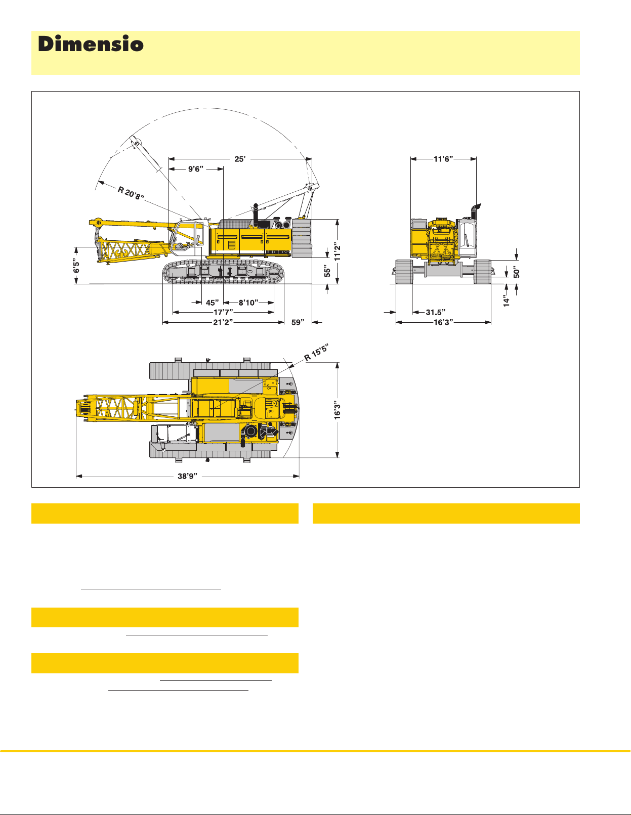
Dimensions
Basic machine with undercarriage
Operating weight
The
operating weight includes the basic machine with HD undercarriage,
2 main winches 55,200 lbs including wire ropes (295 ft) and 36 ft main
boom, consisting of A–frame, boom foot (18 ft) and boom head (18 ft),
lbs basic counterweight, 31.5 inch triple grouser track shoes and
58,000
110,250
lbs hook block.
T
otal weight
approx. 192,000 lbs
Ground pressure
Ground bearin
g p
ressur
e 1
Equipment
Main boo
Fixe
Modular designed equipment for operation as crane, with dragline or
clamshell.
For dragline operation, a rotating fairlead is fitted into the boom foot. This
minimizes
2
m
(No. 1311.xx)
d jib
(No. 0806.xx)
the rope a
HS 855 HD
ngl
max. l
e t
o d
engt
rum
h
, w
hic
h r
esult
223 f
3
6 f
t – 105 f
s i
n l
owe
r rope w
ear.
4 P
Remarks
1. Th
e l
iftin
g c
apacitie
s s
tate
d are v
ali
d for l
iftin
g o
peratio
n only (
corre
ponds wit
2. Crane
3. The
must
value.
4. Additional
b
SI
t
t
5. For
6. Working
7. Th
8. Calculation
and IS
9. Th
(E
10. ANS
h c
s
tandin
w
eigh
b
e d
e d
educte
max. wind s
r
e l
iftin
g c
O 4305 T
e s
tructure
N 1
3001–
I B 3
0.5
ran
e c
g o
t o
f the l
educte
e
quipmen
d t
o get the net l
pee
adi
i are m
apacitie
o
f s
tabilit
abl
s are c
2 / 2
004).
lassificatio
n f
irm
, h
orizonta
iftin
g d
evic
d from the g
t o
n boom (
d p
leas
e r
easure
d from c
s are v
ali
y u
nde
e 1 + 2
, t
alculate
n a
ccordin
l g
e (
hoistin
ros
s l
e.g
iftin
g c
apacity.
efe
r t
o lift c
d for 360 d
r load i
s b
ippin
g a
d a
ccordin
g t
o F
round.
g r
opes
iftin
g c
apacit
. boom w
har
entr
e o
egree
ase
d o
ngl
e 4
g t
o F
.E.M
alkways
t i
n o
f s
win
s o
n DIN 1
º.
.E.M
. 1
.001
, hook b
y t
o o
perator’
g and u
f s
wing.
501
. 1
.00
, c
ran
lock
btai
n a net l
, a
uxiliar
s cab o
nde
9 / part 2 / c
1 – 1998
e g
rou
, s
hackl
y jib) must
r m
r l
oad.
s
p A
e e
iftin
anual.
har
1)
tc.)
g
t 1
Page 3
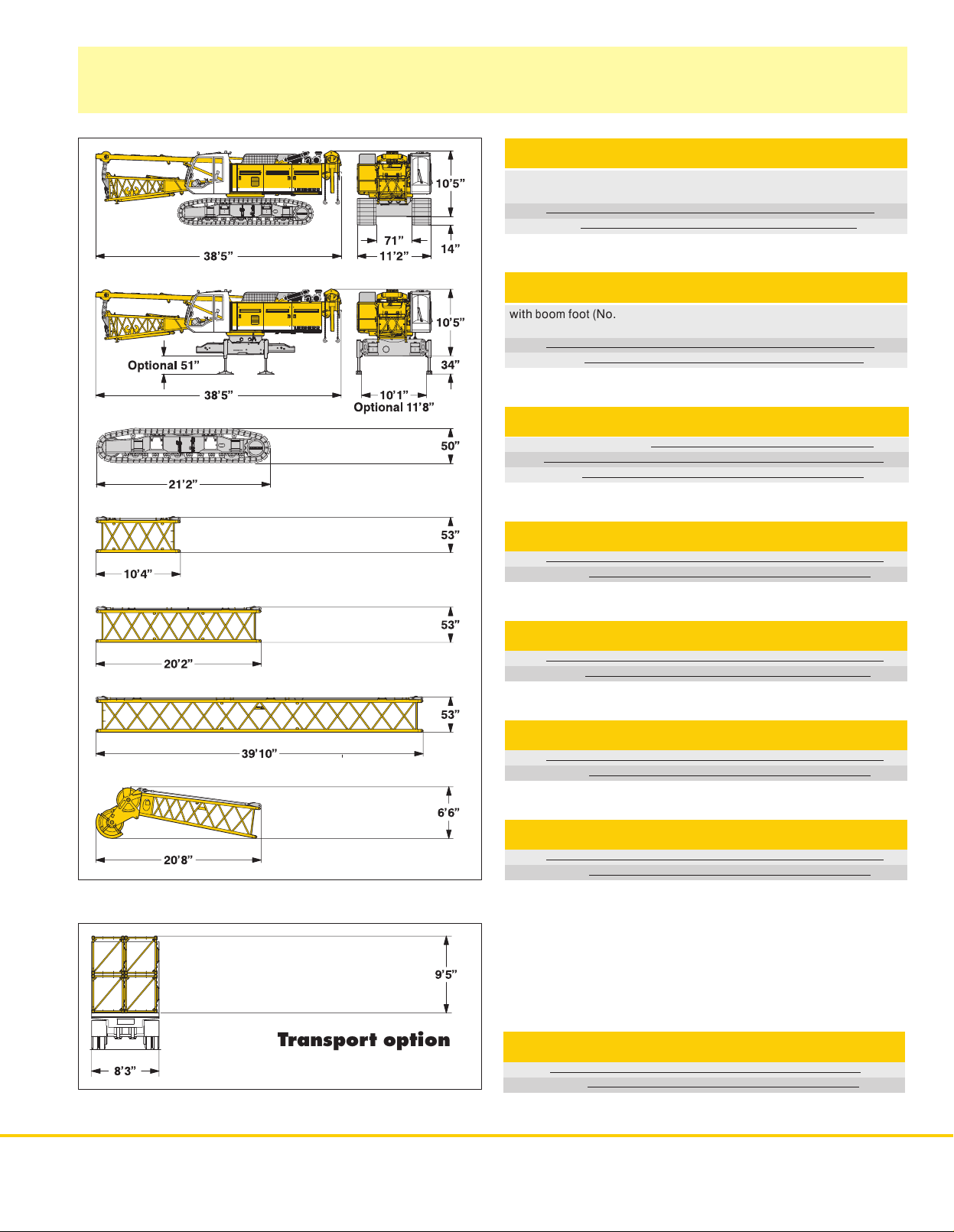
Transport dimensions and weights
Basic machine and boom (No.
131
1.xx)
Basic machine
with HD undercarriage, boom foot (No. 1311.xx), A–frame, 2x 55,200 lbs
including wire ropes (295 ft), without basic counterweight
winches
Width
Weight
in lbs
Basic machine
with boo
m foot (
r
wire
Width
Weight
ope
s (295 ft), w
in lbs
No. 1311.xx)
ithou
t b
, A
asi
Crawler 2x
Triple
grouser track shoes
Width
Weight
in lbs
–frame
, 2
c c
ounterweigh
x 5
5,20
0 lbs w
t and c
inche
rawlers
129,400
s i
ncluding
86,900
21,300
1
1’6”
1
1’6”
31.5”
36”
Boom section (No.
Width
Weight
in lbs*
Boom section (No.
Width
Weightin
lbs*
Boom section (No.
Width
Weight
in lbs*
Boom head (No.
Width
Weight
in lbs*
1
311.xx)
1
311.xx) 10 ft
1
311.xx) 20 ft
1
311.xx) 40 ft
55”
1,100
55”
1,800
55”
2,800
55”
4,350
)
*
Including pendan
t r
opes
Transport option
Boom transport option
Length
W
eight in lbs*
39’10”
1
1,110
HS 855 HD
3
Page 4
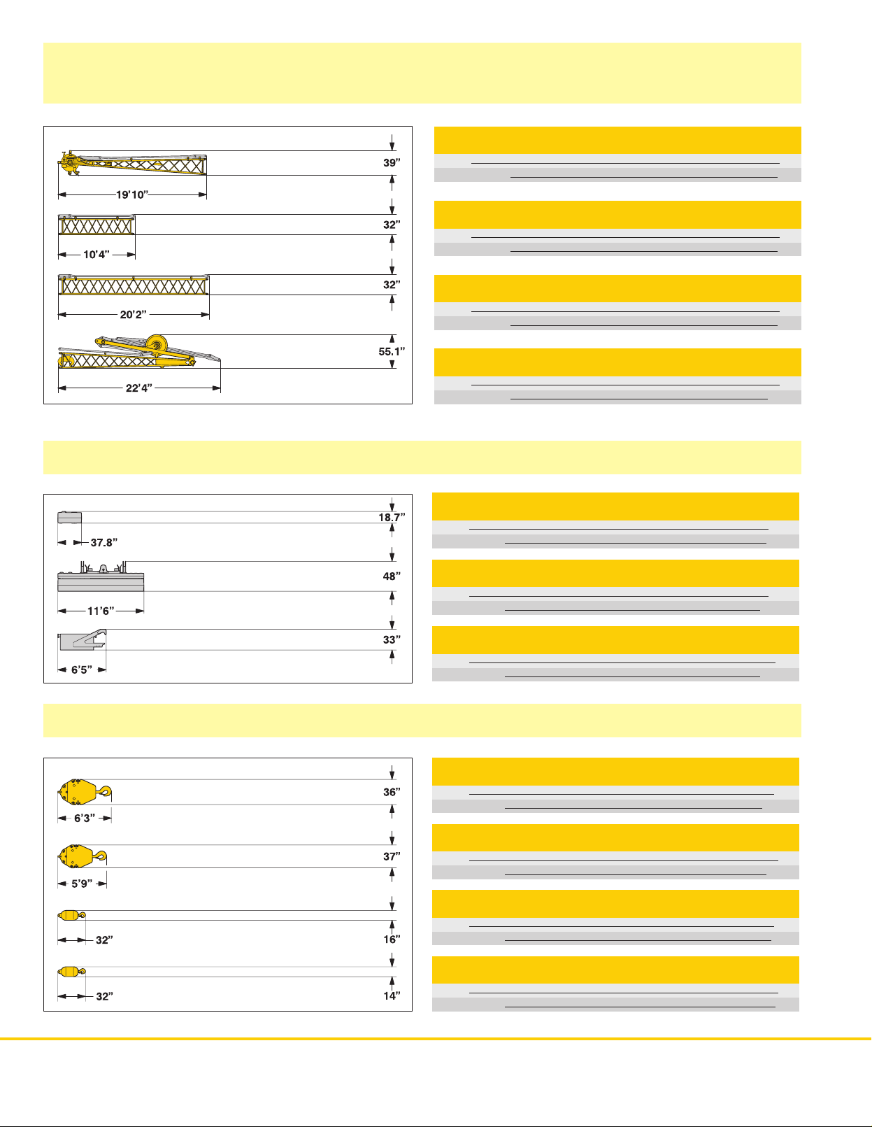
Transport dimensions and weights
Fixed jib (No.
0806.xx)
)
*
Including pendant straps
Counterweight
Fixed jib head (No.
Width
Weight
in lbs*
Fixed jib section (No.
Width
Weight
in lbs*
Fixed jib section (No.
Width
Weight
in lbs*
Fixed jib foot with A-frame (No.
Width
Weight
in lbs*
0
806.16)
0
806.15
0
806.15
45”
980
)
)
0
806.16)
10 ft
38”
245
20 ft
38”
430
59”
2,050
Counterweight 10x
Width
W
eight in lbs
33.5”
3,300
Hooks
Counterweight 1x
Width
W
eight in lbs
41.3”
38,150
Carbody counterweight 2x
Width
Weight
in lbs
5’5”
16,500
110,230 lbs hook block-1sheave
Width
Weight
in lbs
12”
1,650
88,200lbshookblock-1sheave
Width
Weight
in lbs
12”
1,135
55,120 lbs single hook
Width
Weight
in lbs
16”
880
44,100 lbs single hook
Width
Weight
in lbs
14”
660
4HS
855 HD
Page 5

Technical description
Engine
Power rating according to ISO 9249, 450 kW (603 hp) at 1900 rpm
Engine type
Fuel tank
Engine complies with NRMM exhaust certification EPA / CARB Tier 3 and
97/68
EC Stage III
Liebherr D 9508 A7
21
1 gal capacity with continuous level indicator
and reserve warning
Hydraulic system
The main pumps are operated by a distributor gearbox. Axial piston
displacement
needed (flow control on demand). To minimize peak pressure an
automatically
saves energy. The hydraulic oil is cleaned through electronically controlled
pressure
Possible contamination is signalled in the cabin. The use of synthetic
environmentally
Ready
g.
powering casing oscillators, VM vibrators, hydraulic grabs, hanging leads
etc.
Working
Oil tank capacity
pumps work in closed and open circuits supplying oil only when
working pressure cut of
and return filters.
made hydraulic retrofit kits are
friendly oils is possible.
pressure
max. 5076 psi
216 gal
f is integrated. This spares pumps
available to customize requirements e.
and
Boom winch
Main winches
Winch
options:
Line pull (nom. load)
Rope diameter
Drum diameter
Rope speed ft/min
Rope capacity 1st layer
Th
e w
inche
s are o
Clutch and braking functions on the free fall system are provided by a
compact
designed, low wear and maintenance free multi–disc brake.
The
drag and hoist winches use pressure controlled, variable flow hydraulic
motors.
This system features sensors that automatically adjust oil flow to provide
max.
winch speed depending on load.
Option:
Auxiliary winch
T
agline winch
utstandin
g i
35,300 lbs 44,100 lbs
26 mm 30 mm 34 mm
22,8” 24,8”
0–443 0–302
n t
heir compac
170 ft 152 ft
t d
esig
15,500 lbs in boom foot
6,600 lbs with free fall
n and easy a
55,200 lbs
29,5”
0–236
158 ft
ssembly.
Crawlers
The track width of the undercarriage is changed hydraulically
Propulsion through axial piston motor, hydraulically released spring loaded
multi–disc
device.
Flat or triple grouser track shoes 31.5 inch
Drive speed
Option:
F
F
brake, maintenance free crawler tracks,
2 speed hydraulic motor for higher travel speed
Self assembly system, jack up system
.
hydraulic chain tensioning
0 – 0.8 mph
Line pul
l
Rop
e d
iamete
Boo
m u
p 4
r
max. 2
3,20
2
0 m
4 sec. from 15º t
0 l
m
bs
o 8
6º
Swing
Consists of rollerbearing wit
fixed axial piston hydraulic motor, spring loaded and hydraulically released
multi–disc
Swing speed from 0 – 4.9 rpm continuously variable, selector for 3 speed
ranges
Option:
Second swing drive
holding brake, planetary gearbox and pinion.
to increase swing precision.
h e
xternal teeth for lower tooth flank pressure,
Noise emission
Noise emissions correspon
equipmen
t used o
utdoors.
d with 2
000/14/E
C d
irectiv
e on n
ois
e e
missio
n b
y
Control
The
control system – developed and manufactured by Liebherr – is designed
to
withstand
common
shown on a high resolution display
control
Dragline
It is designed for power lifting of the dragline bucket without using the drag
winch
An additional option is the ”Redundant Control System”, whic
restricted
base
On
request, Liebherr also of
free
Operation:
for
winch I and II. Crawler control is actuated with the two
Additionally,
Options:
F
F
F
F
extreme temperature changes and the rough heavy duty tasks
in the construction industry
for all movements, which can be carried out simultaneously
operation: A special
brake.
operation of the machine in the event of a failure on the electronic
control or its sensors.
fers special custom designed control systems
fall winches.
Left joy stick for boom
hand levers can be attached to the pedals.
Special demolition control system
MDE: Machine data recording
PDE: Process data recording
GSM modem
. Complete machine operating data are
. The crane is equipped with proportional
”Interlock” control system is an option available.
winch and swing, right two directional levers
central foot pedals.
.
h a
llows
for
HS 855 HD
5
Page 6

Dragline equipment
58,000 lbs counterweight
Working diagram
C =Radius / dumping radius
J =
Height of boom head sheave centre above
ground level
Capacities
Max. capacities in 1000 lbs do not exceed 75% of tipping load.
in 1000 lbs for boom lengths (46 ft – 95 ft)
46 ft 56 ft 66 ft 75 ft 85 ft 95 ft
C J C J C J C J C J C J
α
45 39.0 37.4 37,9 45.9 44.3 30,6 53.1 51.2 25,1 60.0 58.0 22,3 66.9 19.8 19,0 73.8 72.2 16,5
40 41.6 34.4 34,6 49.2 40.7 28,7 56.8 47.2 23,8 64.3 53.5 20,5 71.8 18.2 17,4 79.4 65.9 15,0
35 43.9 31.5 30,0 52.2 37.1 26,9 60.0 42.7 22,3 68.2 48.2 18,7 76.1 16.5 15,9 84.3 59.7 13,9
30 45.9 28.2 24,9 54.5 33.1 24,5 63.0 38.1 20,3 71.5 43.0 17,2 80.1 14.6 14,6 88.6 52.8 12,6
25 47.6 24.9 23,6 56.4 28.9 22,0 65.6 33.1 18,5 74.4 37.4 15,6 83.3 12.6 13,2 92.2 45,6 11,2
ft ft lbs ft ft lbs ft ft lbs ft ft lbs ft ft lbs ft ft lbs
counterweight 58,000 lbs
6
HS 855 HD
Page 7

Clamshell equipment
58,000 lbs counterweight
Working diagram
C =Radius / dumping radius
J =
Height of boom head sheave centre above
ground level
K =
Length of clamshell (depending on type and
capacity of bucket)
Capacities in 1000 lbs for boom lengths (46 ft – 95 ft)
46 ft 56 ft 66 ft 75 ft 85 ft 95 ft
C J C J C J C J C J C J
α
65 26.6 45.9 56,2 30.5 54.8 48,9 34.8 64.0 41,4 39.0 72.8 35,3 43.0 81.7 28,4 47.2 90.6 26,9
60 29.8 44.3 49,6 34.8 52.8 42,8 39.7 61.4 35,7 44.6 69.9 30,4 49.5 78.4 26,2 54.5 86.9 23,6
55 33.1 42.3 46,1 38.7 50.2 37,3 44.6 58.4 31,3 50.2 66.3 26,9 55.8 74.5 23,2 61.4 82.3 20,5
50 36.4 39.7 41,9 42.7 47.2 33,5 48.9 54.8 27,8 55.1 62.3 24,0 61.7 69.9 20,5 67.9 77.4 17,8
45 39.0 37.4 37,5 45.9 44.3 30,4 53.1 51.2 24,9 60.0 58.1 21,6 66.9 65.0 18,3 73.8 72.2 15,7
40 41.7 34.4 34,2 49.2 40.7 28,0 56.8 47.2 22,9 64.3 53.5 19,4 71.8 59.7 16,5 79.4 65.9 14,1
35 44.0 31.5 29,1 52.1 37.1 26,0 60.0 42.7 21,2 68.2 48.2 17,9 76.1 54.1 15,0 84.3 59.7 12,8
30 45.9 28.2 24,9 54.5 33.1 24,3 63.0 38.1 19,8 71.5 43.0 16,7 80.0 47.9 13,9 88.6 52.8 11,9
25 47.6 24.9 23,6 56.4 28.9 22,0 65.6 33.1 18,3 74.5 37.4 15,7 83.3 41.3 13,2 92.2 45.6 11,0
Max. capacities in 1000 lbs do not exceed 66.7 % of tipping load.
Load diagram restricted by safety factors of standard ropes:
Winches
Rope diameter
Min. breaking load
1–rope clamshell
2–rope clamshell
ft ft lbs ft ft lbs ft ft lbs ft ft lbs ft ft lbs ft ft lbs
44,100
30
182,095
36,400
48,500
lbs
mm
lbf
lbs
lbs
55,2001
34
231,800
46,300
61,750
lbs
mm
lbf
lbs
lbs
counterweight 58,000 lbs
HS
855 HD
7
Page 8

Equipment
Casing oscillator and slurry wall grab
Casing oscillator
Winch options
e s
Lin
Drillin
g d
Maximu
tw
o rope o
8
HS 855 HD
pee
d 1st l
iamete
m a
peratio
aye
r (
ft/min
r
llowabl
e w
eigh
n 4
Slurry wall grab
2
x 4
4,10
0 lbs 2x 5
)
t i
n
8,50
0
–30
6’7”
0 lbs
2
6
5,20
1,75
0
0 l
bs
–236
6
’7”
0 l
bs
Winch options
e s
pee
. c
hise
m a
o rope o
d 1st l
l w
llowabl
peratio
Lin
Max
Maximu
tw
aye
r (
ft/min
)
eigh
t
e w
eigh
t i
n
n 4
2
x 4
4,10
26
0
,50
8,50
0 lbs 2x 5
–30
2
0 lbs
0 lbs
6
5,20
3
1,75
0
5,30
0 l
bs
–236
0 l
0 l
bs
bs
Page 9

Equipment
Dynamic soil compaction
Capacities in 1000 lbs for boom lengths (66 ft – 105 ft)
Boom length
Radius in (ft)
27 55,2 55,2 44,1 44,1 41,9
30 44,1 41,9 41,9 39,7 37,5
Max.
capacities in 1000 lbs do not exceed 75% of tipping load.
All
loads given are max. values and must not be exceeded. They are only permitted in 2 rope automatic operation and are valid for work on a surface
with
max. inclination of 1 %. Lifting heigths must not exceed 82 ft.
66 ft 75 ft 85 ft 95 ft
lbs lbs lbs lbs lbs
105 ft
HS
855 HD
9
Page 10

Working range - main boom (No.
58,000 lbs counterweight
1
311.xx) 86° -15°
Auxiliary jib 55,200 lbs
The maximum capacity of
auxiliary jib is 55,200 lbs.
the
The corresponding load
chart is programmed in the
system.
LMI
Main boom configuration
Configuration fo
Boom foot 1
Boo
m i
nsert 1
Boo
m i
nsert 2
Boo
m i
nsert 4
Boo
m h
ead 1
Boom lengt
*
Additional counterweight allows self erection of boom up to 223 ft.
**Actual lengths of boom sections are metric (e.g. 3 m, 6 m, 12 m). The figures shown above are approximate conversions to feet.
10
HS 855 HD
r boom l
ength
s (36 f
Length Amount of boom e
8 f
t 1 1 1 1 1 1 1 1 1 1 1 1 1 1 1 1 1 1 1 1
0 f
t** 1 1 1 1 1 1 1 1 1 1
0 f
t** 1 1 2 2 3 3 2 2 3 3 2 2 3 3 2 2 3 3
0 f
t** 1 1 1 1 2 2 2 2 3 3 3 3
8 f
t 1 1 1 1 1 1 1 1 1 1 1 1 1 1 1 1 1 1 1 1
h (
ft) 36 46 56 66 75 85 95 105 115 125 135 144 154 164 174 184 194 203 213* 223*
t – 223 f
(table
t)
1 – No. 1
311.xx)
xtensions
Page 11

Lift chart for main boom (No. 1311.xx)
58,000 lbs counterweight
Capacities
58,000 lbs counterweight
Radius 36 46 66 75 85 95 105 115 125 135 144 154 164 174 184 194 203 Radius
(ft)
10.5 200.0 10.5
15 200.0 200.0 193.8 188.3 178.1 157.7 137.6 115.1 99.4 15
20 120.4 120.9 121.2 121.2 121.2 119.2 116.7 114.5 99.4 80.2 67.1 62.1 54.8 48.3 40.4 33.9 20
25 85.4 85.8 86.0 86.0 85.9 85.8 85.7 85.9 84.4 76.7 66.2 62.1 54.8 48.3 40.4 33.9 29.4 25
30 65.6 66.0 66.2 66.1 66.0 65.9 65.7 65.9 65.8 65.6 62.6 58.2 51.9 46.5 40.3 33.9 29.4 30
35 52.8 53.2 53.4 53.3 53.2 53.1 52.9 53.1 52.9 52.7 52.6 52.6 48.8 42.3 37.7 31.9 28.1 35
40 44.5 44.7 44.6 44.5 44.4 44.2 44.4 44.2 44.0 43.8 43.9 43.6 39.7 35.5 30.1 26.5 40
45 37.9 38.1 38.0 37.9 37.7 37.5 37.8 37.6 37.4 37.2 37.2 37.0 36.8 33.6 28.4 24.7 45
50 33.0 33.0 32.8 32.7 32.4 32.7 32.5 32.3 32.1 32.1 31.9 31.7 31.5 27.1 23.4 50
55 29.0 28.9 28.8 28.6 28.4 28.7 28.4 28.2 28.0 28.1 27.9 27.6 27.4 26.2 22.5 55
60 25.7 25.7 25.5 25.3 25.1 25.4 25.2 25.0 24.7 24.8 24.6 24.3 24.1 24.1 21.8 60
65 22.9 22.9 22.8 22.6 22.4 22.7 22.5 22.2 22.0 22.1 21.8 21.6 21.4 21.4 21.1 65
70 20.6 20.5 20.3 20.1 20.4 20.2 20.0 19.7 19.8 19.6 19.3 19.1 19.1 18.8 70
75 18.6 18.5 18.4 18.2 18.4 18.2 18.0 17.7 17.8 17.6 17.4 17.1 17.1 16.9 75
80 16.8 16.7 16.5 16.8 16.5 16.3 16.1 16.1 15.9 15.7 15.4 15.4 15.2 80
85 15.3 15.2 15.0 15.3 15.1 14.8 14.6 14.7 14.4 14.2 13.9 13.9 13.7 85
90 13.9 13.7 14.0 13.8 13.5 13.3 13.4 13.1 12.9 12.6 12.6 12.4 90
95 12.7 12.5 12.8 12.6 12.4 12.1 12.2 12.0 11.8 11.5 11.5 11.2 95
100 11.4 11.8 11.6 11.4 11.1 11.2 11.0 10.7 10.5 10.5 10.2 100
105 10.8 10.6 10.4 10.2 10.3 10.0 9.8 9.5 9.5 9.3 105
110 10.0 9.8 9.6 9.3 9.4 9.2 9.0 8.7 8.7 8.5 110
115 9.0 8.8 8.6 8.7 8.4 8.2 7.9 7.9 7.7 11 5
120 8.3 8.1 7.9 8.0 7.7 7.5 7.2 7.3 7.0 120
125 7.5 7.2 7.3 7.1 6.9 6.6 6.6 6.4 125
130 6.8 6.6 6.8 6.5 6.3 6.0 6.0 5.8 130
135 6.1 6.2 6.0 5.7 5.5 5.5 5.2 135
140 5.5 5.7 5.5 5.2 5.0 5.0 4.7 140
145 5.2 5.0 4.8 4.5 4.5 4.3 145
150 4.8 4.6 4.3 4.1 4.1 3.8 150
155 4.1 3.9 3.7 3.7 3.4 155
160 3.7 3.5 3.3 3.3 3.1 160
165 3.2 2.9 3.0 2.7 165
170 2.8 2.6 2.6 2.4 170
175 2.2 2.3 175
Above lift chart is for reference only
in 1000 lbs for boom lengths (36 ft – 203 ft) – with 55,200 lbs winches
Boom length in (ft)
lbs lbs lbs lbs lbs lbs lbs lbs lbs lbs lbs lbs lbs lbs lbs lbs lbs
. For actual lift duty please refer to lift chart in operator’s cab or manual.
(ft)
HS 855 HD
11
Page 12

Lift chart for main boom (No. 1311.xx)
71,200 lbs counterweight and 33,100 lbs carbody counterweight
Capacities in 1000 lbs for boom lengths (36 ft – 223 ft) – with 55,200 lbs winches
71,200 lbs counterweight and 33,100 lbs carbody counterweight
Boom length in (ft)
Radius 36 56 66 85 105 11 5 125 135 144 154 164 174 184 194 203 213 223 Radius
(ft) lbs lbs lbs lbs lbs lbs lbs lbs lbs lbs lbs lbs lbs lbs lbs lbs lbs (ft)
8.5 230.0* 8.5
10 230.0* 230.0* 10
15 198.4 194.0 198.4 178.1 137.6 115.1 99.4 15
20 149.6 150.3 150.3 140.8 128.7 115.1 99.4 80.2 67.1 62.1 54.8 48.3 40.4 33.9 20
25 106.5 107.1 107.1 107.0 102.0 98.5 90.3 76.7 66.2 62.1 54.8 48.3 40.4 33.9 29.4 25.9 23.2 25
30 82.1 82.6 82.6 82.5 82.2 80.4 75.7 69.4 62.6 58.2 51.9 46.5 40.3 33.9 29.4 25.9 23.2 30
35 66.3 66.9 66.9 66.7 66.4 66.6 66.4 62.2 55.5 54.3 48.8 42.3 37.7 31.9 28.1 25.4 23.2 35
40 56.0 55.9 55.7 55.4 55.6 55.4 54.6 50.3 51.4 46.0 39.7 35.5 30.1 26.5 23.7 21.8 40
45 47.9 47.9 47.6 47.3 47.5 47.3 47.1 42.7 45.8 42.4 37.8 33.6 28.4 24.7 22.3 20.7 45
50 41.8 41.8 41.6 41.2 41.5 41.3 41.1 39.1 40.7 39.0 35.6 32.1 27.1 23.4 21.1 19.6 50
55 36.8 36.9 36.7 36.3 36.5 36.3 36.1 35.9 35.9 35.7 33.4 30.2 26.2 22.5 20.2 18.7 55
60 32.8 32.6 32.3 32.5 32.3 32.1 31.9 31.9 31.7 31.5 28.6 25.4 21.8 19.5 18.0 60
65 29.4 29.3 28.9 29.2 29.0 28.8 28.5 28.6 28.4 28.1 27.4 24.8 21.2 18.9 17.5 65
70 26.5 26.1 26.4 26.2 26.0 25.7 25.8 25.5 25.3 25.1 24.3 20.7 18.4 17.0 70
75 24.1 23.7 24.0 23.8 23.6 23.3 23.4 23.2 22.9 22.7 22.7 20.3 18.0 16.5 75
80 22.0 21.6 21.9 21.7 21.5 21.2 21.3 21.1 20.9 20.6 20.6 19.0 17.4 16.2 80
85 20.1 19.8 20.1 19.9 19.7 19.4 19.5 19.3 19.0 18.8 18.8 17.9 16.4 15.4 85
90 18.2 18.5 18.3 18.1 17.8 17.9 17.7 17.5 17.2 17.2 16.9 15.5 14.5 90
95 16.8 17.1 16.9 16.7 16.4 16.5 16.3 16.0 15.8 15.8 15.5 14.7 13.8 95
100 15.5 15.8 15.6 15.4 15.2 15.3 15.0 14.8 14.5 14.5 14.3 14.0 13.0 100
110 13.7 13.5 13.2 13.0 13.1 12.9 12.6 12.4 12.4 12.1 11.9 11.6 110
120 11.6 11.4 11.2 11.3 11.1 10.8 10.6 10.6 10.3 10.1 9.8 120
130 9.9 9.7 9.8 9.6 9.4 9.1 9.1 8.9 8.6 8.3 130
140 8.4 8.5 8.3 8.1 7.8 7.8 7.6 7.3 7.1 140
145 8.0 7.7 7.5 7.2 7.3 7.0 6.8 6.5 145
150 7.4 7.2 7.0 6.7 6.7 6.5 6.2 6.0 150
155 6.7 6.5 6.2 6.2 6.0 5.7 5.5 155
160 6.2 6.0 5.7 5.8 5.5 5.3 5.0 160
165 5.6 5.3 5.3 5.1 4.9 4.6 165
170 5.1 4.9 4.9 4.7 4.4 4.2 170
175 4.5 4.5 4.3 4.1 3.8 175
180 4.1 4.2 3.9 3.7 3.4 180
185 3.8 3.6 3.3 3.1 185
195 2.9 2.7 2.4 195
Above lift chart is for reference only
*) With heavy duty boom head
. For actual lift duty please refer to lift chart in operator’s cab or manual.
12 HS
855 HD
Page 13

Working range - fixed jib (No.
Main boom 86°-30°
0
806.xx
)
15° and 30°
Boom configuration for boom lengths (36 ft - 184 ft) –
see t
abl
e 1 o
n page 1
0
Fixed jib configuration for fixed jib lengths (36 ft - 105 ft)
Length Amount
Fixed jib foot
Fixed jib insert
Fixed jib insert
Fixed jib head
Fixed jib length (ft)
*Actual lengths of boom sections are metric (e.g. 3 m, 6 m). The figures shown above are approximate conversions to feet.
18 ft
10 ft*
20 ft*
18 ft
1 1 1 1 1 1 1 1
1 1 1 1
0 0 1 1 2 2 3 3
1 1 1 1 1 1 1 1
36 46 56 66 76 85 95 105
of fixed jib extensions
HS
855 HD
13
Page 14

Lift chart - fixed jib (No. 0806.xx)
Offset 15°
Main boom 36 ft
Fixed
jib length in (ft)
36 66 85 105
Radius (ft)
16.8 60.4
35 41.8 25.1
40 38.8 23.4 16.2
50 34.9 21.0 13.1 9.5
55 33.6 20.2 12.5 9.2
60 32.2 19.5 11.9 8.9
65 30.4 18.9 11.4 8.7
80 16.3 10.1 8.0
95 14.5 9.0 7.5
110 8.4 7.2
120 7.0
130 6.8
lbs lbs lbs lbs
Main boom 105 ft
Fixed
jib length in (ft)
36 66 85 105
Radius (ft)
24 48.4
40 39.3 21.7
50 36.5 20.3 13.2
60 32.0 19.5 12.5 8.9
80 21.2 18.4 11.3 8.2
90 17.8 17.8 10.8 7.9
100 15.0 16.1 10.3 7.7
110 12.8 13.9 9.8 7.5
120 11.0 12.0 9.5 7.3
150 7.9 8.3 6.8
170 6.4 6.6
190 5.1
lbs lbs lbs lbs
Main boom 66 ft
Fixed
jib length in (ft)
36 66 85 105
Radius (ft)
19.9 56.1
35 43.1 24.5
45 38.8 21.9 14.0
55 36.0 20.5 12.9 9.2
60 33.1 20.1 12.4 8.9
70 26.9 19.2 11.6 8.6
80 22.4 18.4 10.8 8.2
85 20.5 17.8 10.5 8.0
90 18.9 17.2 10.2 7.9
120 13.0 8.7 7.2
140 8.2 6.9
160 6.6
lbs lbs lbs lbs
Main boom 125 ft
Fixed
jib length in (ft)
36 66 85 105
Radius (ft)
26.1 41.8
40 36.6 21.7
50 33.9 19.3 12.9
60 31.8 18.6 12.3 8.7
80 21.0 17.8 11.3 8.1
100 14.8 15.9 10.5 7.7
120 10.8 11.7 9.7 7.3
130 9.3 10.2 9.3 7.1
140 7.9 8.8 8.9 7.0
170 5.7 6.1 6.5
190 4.5 4.9
195 4.5
lbs lbs lbs lbs
Main boom 85 ft
Fixed
jib length in (ft)
36 66 85 105
Radius (ft)
22 52.7
40 40.7 22.8
45 38.7 21.7 15.1
55 35.9 20.4 12.9 9.1
60 32.6 19.9 12.5 8.9
70 26.3 19.3 11.8 8.6
80 21.8 18.6 11.2 8.2
90 18.3 18.0 10.6 7.9
105 14.4 15.5 9.8 7.5
135 10.2 8.6 7.0
155 8.2 6.7
175 6.5
lbs lbs lbs lbs
Main boom 144 ft
Fixed
jib length in (ft)
36 66 85 105
Radius (ft)
28.1 36.6
45 31.8 18.3
55 29.3 17.6 12.2
60 28.1 17.4 11.9 9.0
80 20.5 16.7 11.1 8.0
100 14.3 15.2 10.3 7.6
120 10.2 11.2 9.6 7.2
140 7.4 8.3 8.7 6.9
160 5.2 6.1 6.5 6.5
175 4.7 5.2 5.5
180 4.8 5.1
185 4.7
lbs lbs lbs lbs
Main boom 164 ft
Fixed
jib length in (ft)
36 66 85 105
Radius (ft)
30.2 31.5
45 28.4 16.9
55 26.7 16.2 11.6
65 23.9 15.9 11.2 8.0
80 20.2 15.2 10.8 7.7
100 14.0 14.3 9.7 7.4
120 9.9 10.9 9.1 7.1
140 7.1 8.0 8.4 6.8
165 4.5 5.3 5.7 6.1
175 4.5 4.9 5.2
180 4.5 4.8
185 4.4
Capacitie
For
a
ctua
14 HS
855 HD
lbs lbs lbs lbs
s i
n 1000 lbs with f
l lift duty and c
ixe
omplet
d jib (No. 0
e c
har
t with all a
806.xx)
Main boom 174 ft
Fixed
36 56 66 76
, 7
1,20
vailabl
Radius (ft)
31.2 28.8
45 26.1 18.7 17.2
50 25.1 18.3 15.7 14.5
60 23.3 17.7 15.2 13.1
80 19.6 16.3 14.4 12.6
100 13.7 14.5 13.3 10.6
120 9.7 10.4 10.6 9.5
140 6.8 7.4 7.7 8.0
160 4.7 5.3 5.5 5.8
165 4.8 5.1 5.3
170 4.6 4.8
175 4.4
0 lbs c
e c
onfiguration
lbs lbs lbs lbs
ounterweigh
s p
leas
jib length in (ft)
t + 33,10
e r
efe
0 lbs c
r t
o l
ift char
arbod
t i
Main boom 184 ft
36 46 56
Radius (ft)
y c
ounterweight
n o
perator’s ca
32.2 25.4
40 24.4 21.2
45 23.6 20.7 17.7
60 21.6 19.1 16.7
80 17.8 16.6 15.3
100 13.4 13.8 13.8
120 9.4 9.7 10.1
130 7.8 8.2 8.5
140 6.5 6.8 7.2
150 5.4 5.7 6.0
160 4.4 4.7 5.0
165 4.5
lbs lbs lbs
. A
bov
e lift c
b o
r m
anual.
Fixed
jib length in (ft)
har
t i
s for r
eferenc
e o
nly.
Page 15

Lift chart - fixed jib (No. 0806.xx)
Offset 30°
Main boom 36 ft
Fixed
jib length in (ft)
36 66 85 105
Radius (ft)
25.5 40.7
50 26.2 16.3
60 23.2 14.5 11.9
65 22.2 13.8 10.3
75 12.5 9.6 7.7
90 11.2 8.7 6.9
95 11.0 8.4 6.7
110 7.8 6.1
115 7.7 5.9
120 5.8
130 5.5
135 5.5
lbs lbs lbs lbs
Main boom 105 ft
Fixed
jib length in (ft)
36 66 85 105
Radius (ft)
32.7 35.8
55 30.5 16.0
70 26.5 14.9 10.2
80 21.8 14.0 9.8 7.9
90 18.2 13.4 9.5 7.2
100 15.4 12.7 9.1 6.9
110 13.1 12.1 8.8 6.6
120 11.2 11.7 8.5 6.4
125 10.3 11.5 8.4 6.3
155 7.5 7.8 5.7
175 6.1 5.5
195 4.9
lbs lbs lbs lbs
Main boom 66 ft
Fixed
jib length in (ft)
36 66 85 105
Radius (ft)
28.6 39.0
50 30.0 16.8
65 25.8 14.7 10.6
80 22.7 13.2 9.7 7.5
90 19.1 12.3 9.2 7.1
95 17.5 12.0 8.9 6.9
110 11.2 8.4 6.4
120 11.0 8.0 6.1
130 7.8 5.9
140 7.7 5.7
150 5.5
160 5.5
lbs lbs lbs lbs
Main boom 125 ft
Fixed
jib length in (ft)
36 66 85 105
Radius (ft)
34.7 33.6
55 29.8 17.0
70 26.3 14.5 9.6
85 19.7 13.7 9.4 7.3
100 15.2 13.0 9.1 6.9
110 13.0 12.4 8.9 6.7
120 11.1 12.0 8.6 6.4
130 9.5 10.6 8.4 6.2
140 8.1 9.2 8.2 6.0
170 5.8 6.4 5.6
190 4.7 5.2
200 4.4
lbs lbs lbs lbs
Main boom 85 ft
Fixed
jib length in (ft)
36 66 85 105
Radius (ft)
30.6 37.6
55 30.0 16.2
65 27.5 15.1 10.5
80 22.3 13.7 9.8 7.5
90 18.7 12.9 9.4 7.2
100 15.8 12.3 9.0 6.8
110 13.5 11.7 8.6 6.5
130 11.0 8.0 6.0
140 9.7 7.8 5.8
160 7.7 5.5
170 5.5
180 5.5
lbs lbs lbs lbs
Main boom 144 ft
Fixed
jib length in (ft)
36 66 85 105
Radius (ft)
36.8 30.5
60 27.2 13.2
75 23.4 12.9 8.7
85 19.3 12.8 8.6 7.1
100 14.8 12.6 8.5 6.8
120 10.6 11.7 8.5 6.4
140 7.6 8.8 8.2 6.1
150 6.4 7.5 8.1 5.9
160 5.4 6.4 7.0 5.8
180 4.5 5.1 5.4
185 4.7 5.2
195 4.4
lbs lbs lbs lbs
Main boom 164 ft
Fixed
jib length in (ft)
36 66 85 105
Radius (ft)
38.8 27.2
60 23.8 15.9
75 20.8 11.4 7.6
90 17.3 11.1 7.5 6.8
100 14.5 10.7 7.5 6.3
120 10.3 10.2 7.5 5.5
140 7.4 8.5 7.5 5.5
160 5.2 6.2 6.8 5.5
165 4.7 5.7 6.3 5.5
175 4.8 5.3 5.5
185 4.5 5.0
190 4.6
Capacitie
For
a
ctua
lbs lbs lbs lbs
s i
n 1000 lbs with f
l lift duty and c
ixe
omplet
d jib (No. 0
e c
har
t with all a
806.xx)
Main boom 174 ft
Fixed
36 56 66 75
, 7
1,20
vailabl
Radius (ft)
39.9 24.6
55 22.2 13.7
60 21.6 13.6 11.3
70 20.1 12.7 10.8 8.9
80 18.5 12.1 10.3 8.5
100 14.3 11.4 10.0 8.4
120 10.1 10.5 9.8 8.2
140 7.2 8.0 8.3 7.8
165 4.5 5.2 5.5 5.8
170 4.7 5.0 5.3
175 4.6 4.9
180 4.4
0 lbs c
e c
onfiguration
lbs lbs lbs lbs
ounterweigh
s p
leas
jib length in (ft)
t + 33,10
e r
efe
0 lbs c
r t
o l
ift char
arbod
Main boom 184 ft
Radius (ft)
40.9 22.1
55 20.6 18.3 16.5
60 20.0 17.4 15.4
80 17.2 15.9 14.4
100 14.0 13.9 12.9
120 9.8 10.3 10.8
130 8.2 8.7 9.1
140 6.9 7.3 7.7
150 5.7 6.1 6.5
160 4.7 5.0 5.4
165 4.6 4.9
170 4.5
y c
ounterweight
t i
n o
perator’s ca
b o
. A
bov
r m
Fixed
jib length in (ft)
36 46 56
lbs lbs lbs
e lift c
har
t i
anual.
s for r
HS
eferenc
855 HD
e o
nly.
15
Page 16

Self assembly system
Unloading
Unloading and assembly of crawlers
Unloading of basic machine (standard)
of basic machine (option)
Unloading and assembly of carbody counterweight
Unloading and assembly of counterweight
Assembly of boom and reeving of hoist ropes
Liebherr-Werk Nenzing GmbH
P. O .
Box 10, A
Te l. : + 4
Fax: +4
crawler.crane@liebherr.com
www.liebherr.com
3 5
3 5
080
080
–671
9 4
9 4
0 N
enzing/Austria
1 – 4
73
1 – 4
99
Unloading and assembly of boom
855 HD – 10223034 – 02/2008 Subject to change without notice.
HS
 Loading...