

Page 1
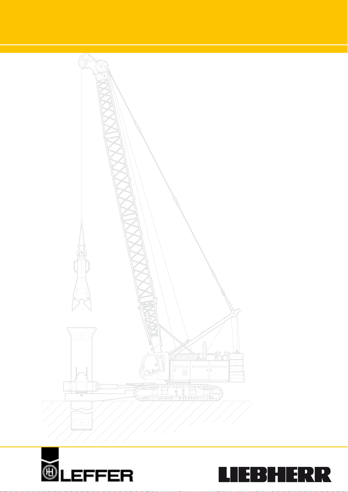
Casing Rotator
Casing Oscillators
Casings up to 3000
Special Hammer Grab
Chisels
Interlocking Tremie Pipes
Page 2
Hydraulic
A
B
H2 H1
S
D
L
A
C 2400-3400
Hub
F
L M
Y
K
Z
C
E
H2 H1
A
B
A
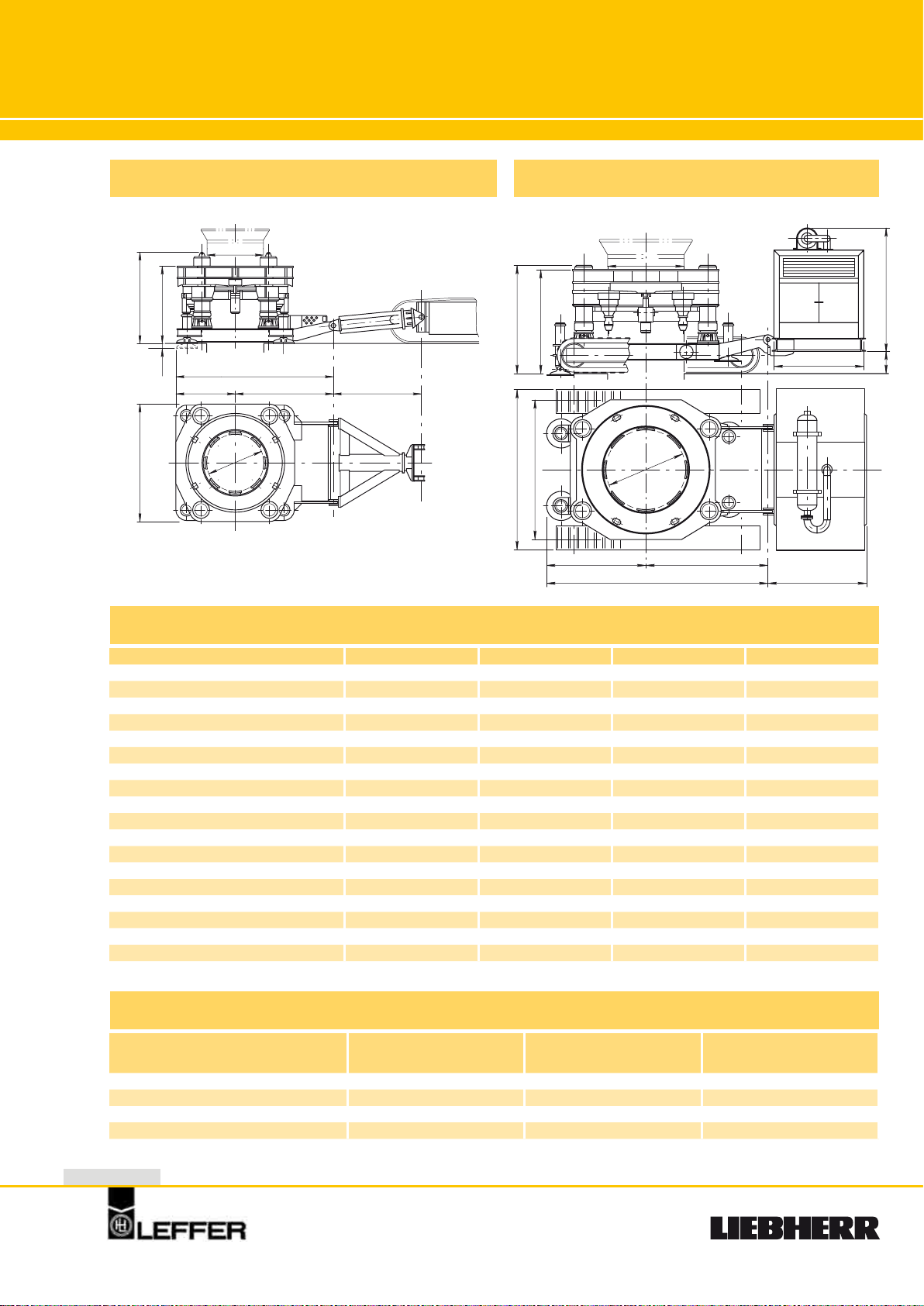
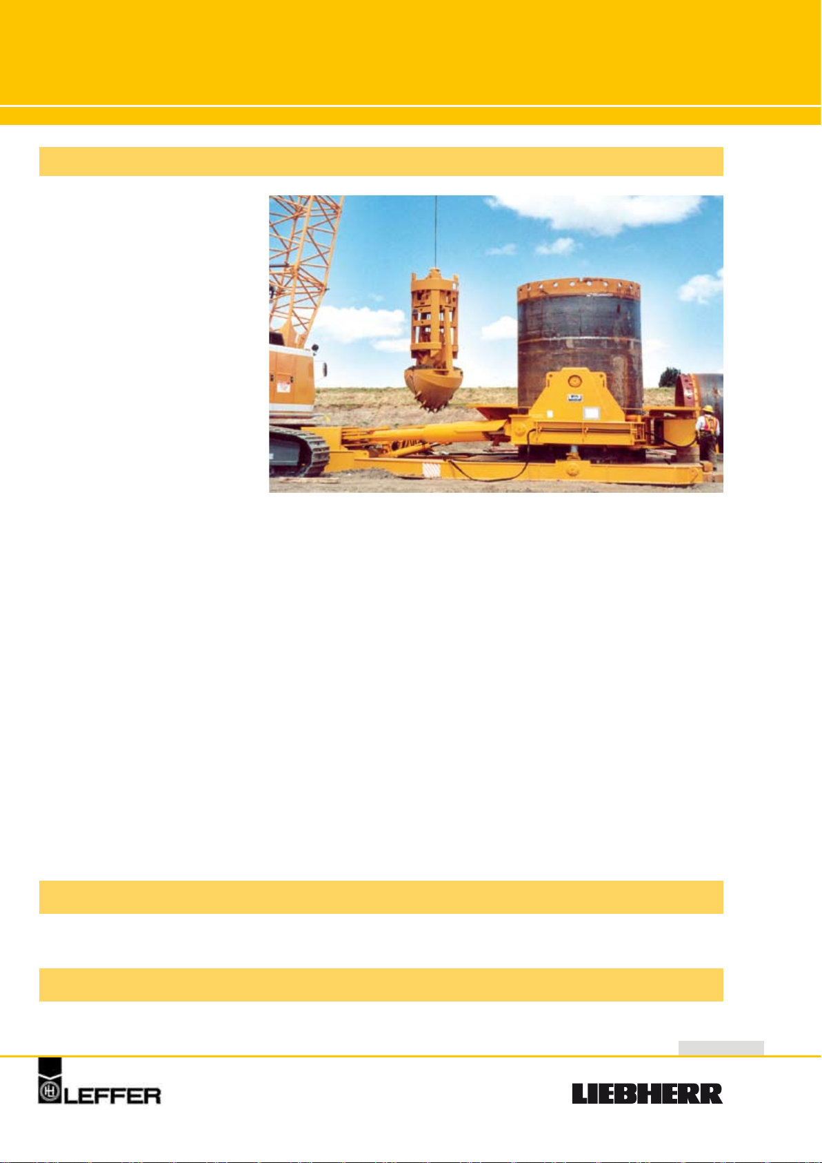
Casing Rotator
RDM/RDM-M
Hydraulic Casing Rotator Type RDM
Technical Data Type RDM und Type RDM-M
Type RDM-M
RDM 1500 RDM 2000 RDM 2500 RDM 3000
A
Max./min. casing dia mm 1500-800 2000-1200 2500-1500 3000-2000
L x B
Length x width
C
D
Min. spacing mm 1550 2530 3000 3200
E
Width mm 4000 4000 5300 5730
F
Min. spacing mm 2200 2600 3000 3200
H1/H2
RDM-M
Technical Data Hydraulik Power Pack
Power kW 273 338 485
Pump rating l / min 2 x 280 – 1 x 200 3 x 300 – 1 x 200 2 x 600 – 1 x 300
Dimensions (XYZ) mm 4000 x 1900 x 2200 4000 x 2200 x 3000 5500 x 2400 x 3000
Weight t 7 12 20
2
Height min. / max. mm 2050 / 2320 2600 / 2695 2600 / 2695 2600 / 2695
K
M
S
Lifting stroke mm 600 600 600 600
Lifting force KN 1890 2400 3750 4560
Rotation speed rpm 0 - 1,1 0 - 1,0 0 - 1,1 0 - 0,9
Torque KNm 2300 2900 4700 7400
Casing retaining force KN 800 800 1200 1500
Working pressure bar 250 (max. 300) 250 (max. 300) 250 (max. 300) 250 (max. 300)
RDM
Weight t 32 42 68 80
Weight t 44 65 97 115
mm 4150 x 3100 6100 x3500 6200 x4300 6500 x4600
mm 2600 3550 3000 3200
mm 800 900 900 900
mm 2000 2100 2600 2600
mm 150 350 450 450
760 / 370
RDM 1500 / RDM 2000
1100 / 460
RDM 2500
1500 / 660
RDM 3000
Page 3
Hydraulic
Casing Rotator
General Remarks
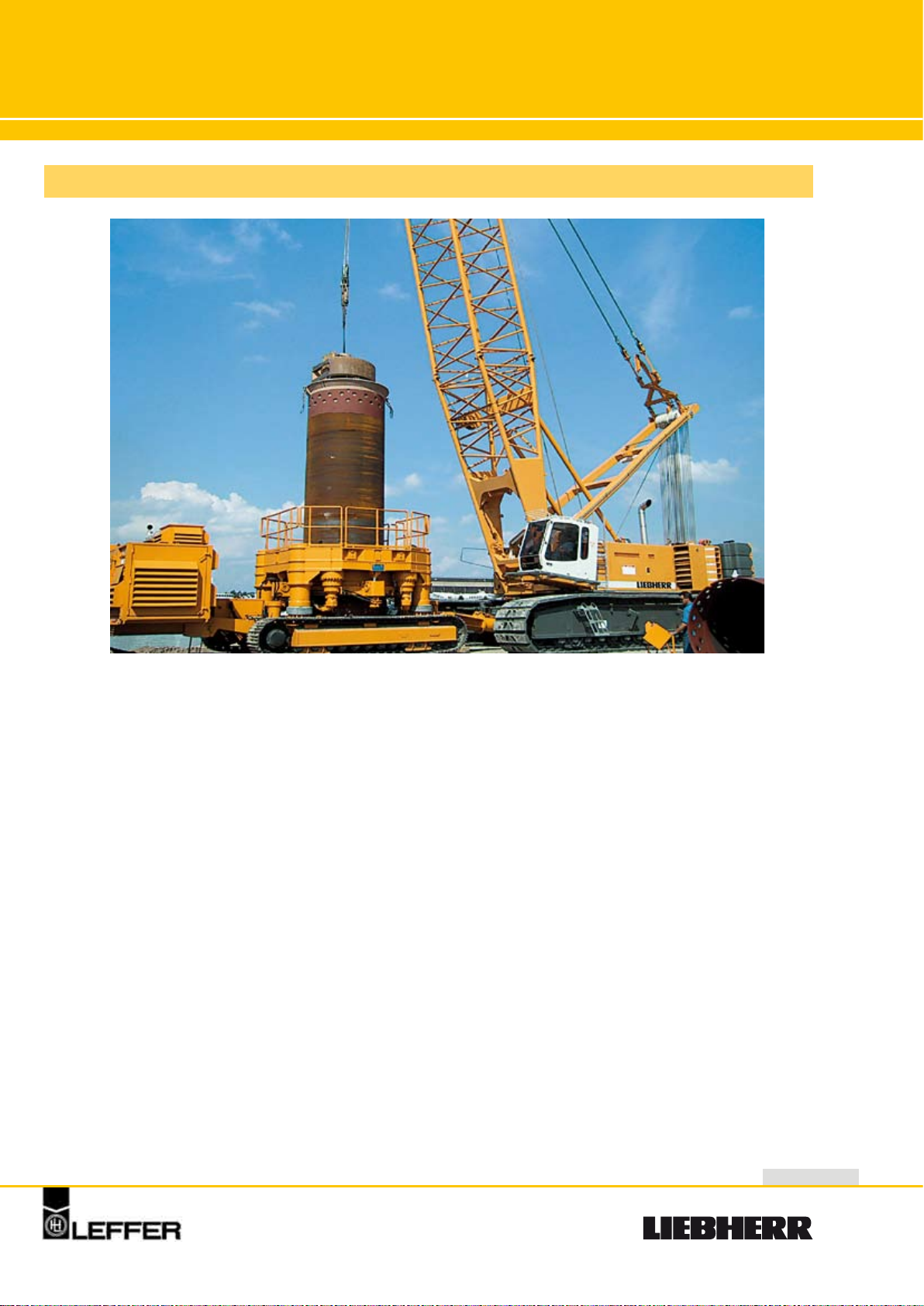
RDM/RDM-M
RDM-M 2000 in operation
The hydraulic full 360 degree turning casing rotators
are economically used to construct bored piles with
the full casing method under hard soil conditions.
The continuous cutting of the hard ground guarantees a boring speed satisfying today's requirements, even for compressive resistance of up to
2500 kg/cm2.
The full 360 degree continuous turning of the casing
minimizes the friction compared to the oscillating
method allowing the casing to drill down to 100 m
depth with the casing rotator machines.
The first casing is fitted with carbide bits which can
be adapted to the requirements of the soil conditions offering major advantages when coring
through hard rock layers or when constructing
secant walls.
The full 360 degree continuous turning of the casing
by powerfull hydraulic motors eliminates the possibility of pile misalignment.
Beyond that, the casing rotators are especially suitable for the construction of full casing displacement
piles because of the ability to apply very high
torque, push down and lifting forces on the casing
which is not possible with the known drilling rigs.
3
Page 4
Hydraulic
P
C G
B
A
D
L
M
F
E
J
K
I
H
N
O
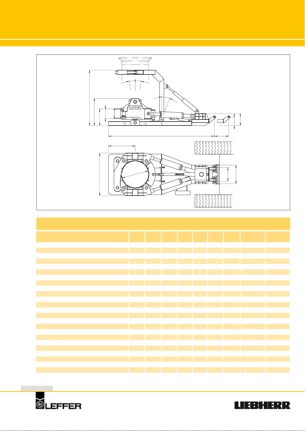
Casing Oscillators
VRM
Technical Data
VRM VRM VRM VRM VRM VRM VRM VRM VRM
1300 1500 2000 2200 2500 2800 3000 3000T1100 3300T1260
Stroke
Lifting force
Clamping force
Rotation angle
Torque
Operating pressure
Travel of casing
Weight
A
Max. casing diameter mm 1300 1500 2000 2200 2500 2800 3000 3000 3300
B
Width of machine mm 2350 2850 3200 3400 4000 4300 4500 4500 4880
C
Length of machine mm 6500 6500 7500 7500 8800 9100 9140 9900 10470
D
Min. spacing mm 1200 1300 1600 1730 2230 2400 2600 2670 2950
E
Width of cradle mm 1015 1015 1015 1015 1015 1015 1015 1015 1015
F
Width of machine excavator side mm 1200 1400 1400 1400 1500 1500 1500 1600 1600
G
Cradle path mm 1300 1600 1300 1300 - - - - -
H
Axis excavator side mm 700 700 700 700 700 700 700 700 700
I
Height of machine excavator side mm 870 870 900 940 1130 1130 1165 1225 1265
J
K
L
M
N
O
P
Height of cradle guide mm 600 650 650 650 700 700 800 800 800
Height from ground to top of cradle guide mm 1100 1200 1300 1300 1400 1400 1500 1500 1620
Height of machine mm 1800 1850 1950 2050 2580 2580 2610 2610 2730
Height of casing guide mm 2820 3220 3220 3220 - - - - Angle of inclination, in front ° 6 6 6 6 - - - - Angle of inclination, in rear ° 8 8 8 8 - - - - Angle of inclination, casing guide ° 20 20 20 20 - - - - -
The casing oscillators can be kept in continuous operation with the specified torque and forces.
mm 600 600 600 600 650 650 650 650 650
kN 1530 2050 2650 2650 5150 7250 7250 7250 9000
kN 1320 1660 2170 2170 3780 4780 4780 4780 5100
° 25 25 25 25 25 22 21 21 24
kNm
1660 2900 4110 4520 7070 8000 8350 11000 12620
bar 270 270 270 270 300 300 300 300 300
mm 284 327 436 480 546 538 550 550 690
t 12 17 25 27 40 48 52 54 63
4
Page 5
Hydraulic
Casing Oscillators
General Remarks
The hydraulic casing oscillators
have been designed in accordance with the latest technical
know-how. Extremely sturdy construction guarantees cost-effective use on site. By means of exact statical calculations in conjunction with higher quality material, an optimum conformity of
loads, weight and material
strength is achieved. The internal
wielding stresses – difficult to determine for static calculations,
which would affect the construction considerably – are eliminated
by means of stress relieving prior
to machining. A prominent feature
of the equipment is the clamping collar consisting
of five links operating on the boring implement. The
individual links surround the casing like a chain so
that a consistent surface pressure is exerted on the
casing circumference. In addition, the large height
of the collar (600 to 800 mm) prevents any damage
to the casings. By means of easily exchangeable
reducer pieces the oscillator can be converted,
within a few minutes, to a smaller casing diameter.
The collar opens uniformly and enables unproblematic insertion of the casing with the cutting shoe.
Another advantage of the machine is the low height
on the excavator side. The excavator can be swiveled by 360° in coupled condition.
VRM 3000 in operation
VRM
Attachment at the excavator itself is torque rigid
and guarantees the transmission of the full rotating
movement of 25° to the casing if the excavator is
firmly situated.
The design and construction of the casing oscillator
is based on the experience of many years of co-operation with companies specializing in pile foundations. In view of the high costs which would result
from a breakdown of the equipment on-site, great
emphasis has been put on exeptionally sturdy construction.
Accessories
• Upper tube guide
• Inserts
Special types
Short series for the use with rotary boring equipment or light duty types please refer to the special brochure!
• Lower locking device
• Suspension
• Power pack
• Hose unit
5
Page 6
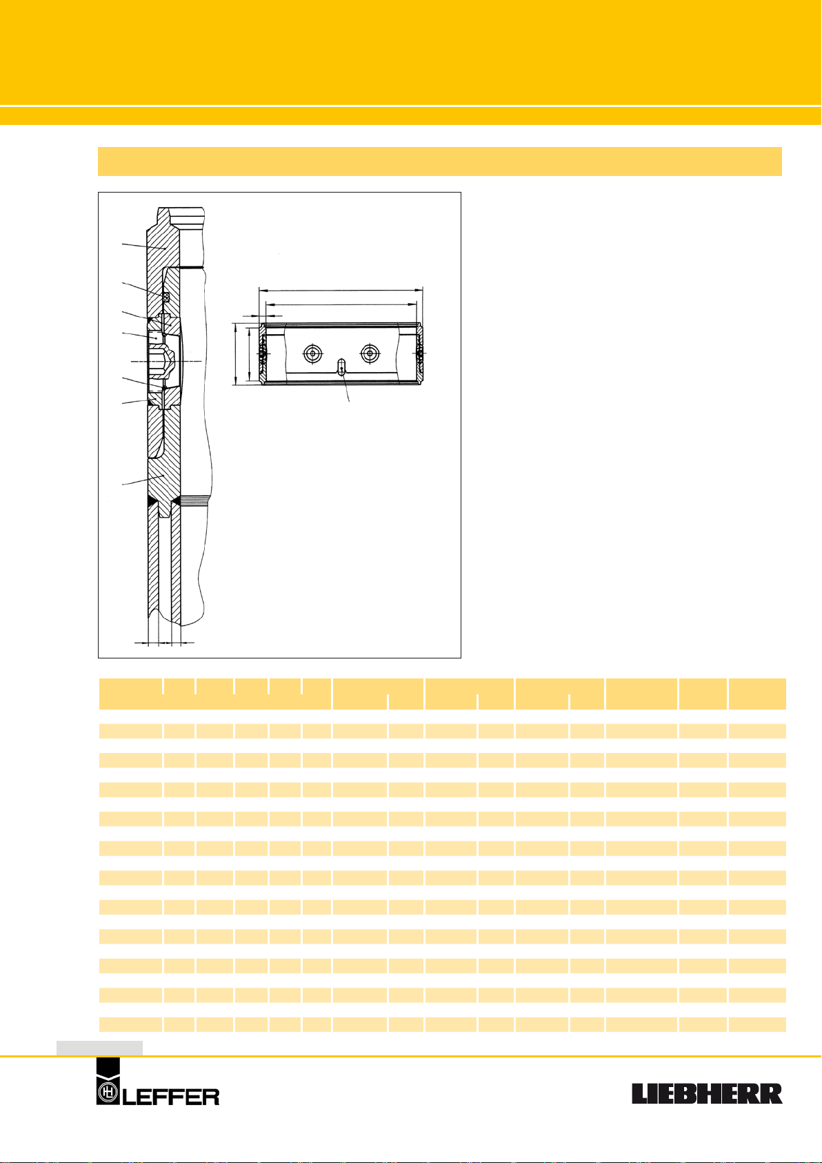
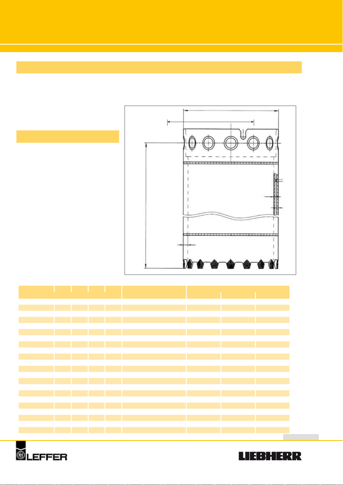
Casing Joint
Technical Data
1
7
4
6
8
5
2
s1 s2
H h
∅ D1
s
∅ D2
3
1. Female Part
2. Male Part
3. Locating Key
4. Conical Ring
5. Threaded Ring
6. Bolt
7. Sealing
8. O-Ring
D1/D2 H1 H2 S1 S2 B Conical ring Threaded ring Conical bolt Locating key Sealing Weight
mm Quantity Type Quantity Type Quantity Type Quantity mm kg
540/478
620/558
600/520
620/540
640/560
660/580
700/620
710/630
720/640
750/670
800/720
880/800
900/820
1000/920
1080/1000
1180/1100
1200/1120
1250/1170
1300/1220
1500/1420
1800/1720
2000/1910
6
340 380 10 8 31 6 K 61 6 G 61 6 29 S 3 - 130
340 380 10 8 31 8 K 61 8 G 61 8 29 S 4 - 150
340 380 15 10 40 8 K 64 8 G 64 8 38 S 4 10 x 510 197
340 380 15 10 40 8 K 64 8 G 64 8 38 S 4 10 x530 199
340 380 15 10 40 8 K 64 8 G 64 8 38 S 4 10 x 550 205
340 380 15 10 40 8 K 64 8 G 64 8 38 S 4 10 x550 212
340 380 15 10 40 8 K 64 8 G 64 8 38 S 4 10 x 610 226
340 380 15 10 40 8 K 64 8 G 64 8 38 S 4 10 x630 230
340 380 15 10 40 8 K 64 8 G 64 8 38 S 4 10 x 630 232
340 380 15 10 40 10 K 88 10 G 88 10 38 S 4 10 x655 266
340 380 15 10 40 10 K 88 10 G 88 10 38 S 4 10 x 700 286
340 380 15 10 40 10 K 88 10 G 88 10 38 S 4 10 x785 315
340 380 15 10 40 10 K 88 10 G 88 10 38 S 4 10 x 785 318
340 380 15 10 40 10 K 88 10 G 88 10 38 S 4 10 x900 327
340 380 18 10 40 12 K 118 12 G 118 12 38 S 4 12 x 975 336
340 380 18 10 40 12 K 118 12 G 118 12 38 S 4 12 x1075 414
340 380 18 10 40 12 K 118 12 G 118 12 38 S 4 12 x 1075 418
340 380 18 10 40 12 K 118 12 G 118 12 38 S 4 12 x1145 421
340 380 18 10 40 12 K 118 12 G 118 12 38 S 4 12 x 1200 425
340 380 18 10 40 18 K 150 18 G 150 18 38 S 6 12 x1370 535
430 470 18 10 40 20 K 150 20 G 150 20 38 S 5 12 x 1680 724
385 425 18 12 45 20 K 200 20 G 200 20 43 S 5 12 x1880 874
Page 7
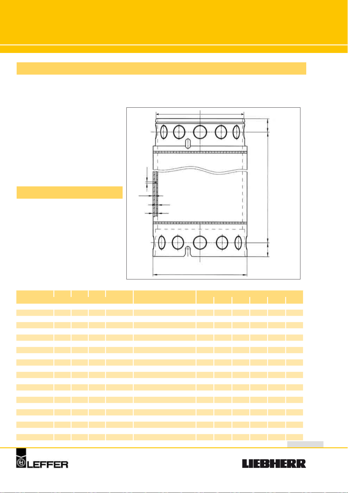
Casings
and Accessories
General Remarks
The casings are designed to create cased holes down to a depth
of 35 m. Especially for the construction of bored piles by rotary
drilling rigs precisely fitting casing
joints guarantee a fast placement
and bolting of the casings as well
as ideal power transmission.
D2
114
∅ d
Technical Data
s1
s2
B
Double-walled
∅ D1
D1/D2 S1 S2 d B Z L - Working length (kg)
mm Quantity of longitudinal bars 1 m 2 m 3 m 4 m 5 m 6 m
540/478
620/558
600/520
620/540
640/560
660/580
700/620
710/630
720/640
750/670
800/720
880/800
900/820
1000/920
1080/1000
1180/1100
1200/1120
1250/1170
1300/1220
1500/1420
1800/1720
2000/1910
10 8 10 31 16 295 535 770 1015 1255 1495
10 8 10 31 18 335 610 895 1185 1440 1720
15 10 13 40 18 440 805 1170 1540 1905 2270
15 10 13 40 18 450 830 1205 1590 1970 2345
15 10 13 40 18 465 855 1245 1640 2030 2420
15 10 13 40 18 480 880 1285 1690 2095 2495
15 10 13 40 20 510 940 1370 1805 2230 2660
15 10 13 40 21 520 950 1385 1820 2255 2690
15 10 13 40 21 530 960 1410 1860 2305 2755
15 10 13 40 22 575 1035 1495 1965 2425 2890
15 10 13 40 24 615 1110 1600 2105 2600 3095
15 10 13 40 26 670 1215 1760 2315 2860 3405
15 10 13 40 26 685 1245 1805 2370 2930 3485
18 10 10 40 30 780 1465 2145 2840 3525 4210
18 10 10 40 32 830 1570 2310 3060 3800 4540
18 10 10 40 36 925 1740 2550 3370 4185 4995
18 10 10 40 36 965 1790 2615 3440 4280 5396
18 10 10 40 38 995 1855 2715 3585 4450 5410
18 10 10 40 40 1025 1920 2810 3725 4620 5520
18 10 10 40 45 1225 2265 3300 4350 5390 6430
18 10 10 40 55 1460 2750 4040 5320 6610 7900
18 12 13 45 62 1590 3080 4570 6060 7550 9050
L
115
7
Page 8
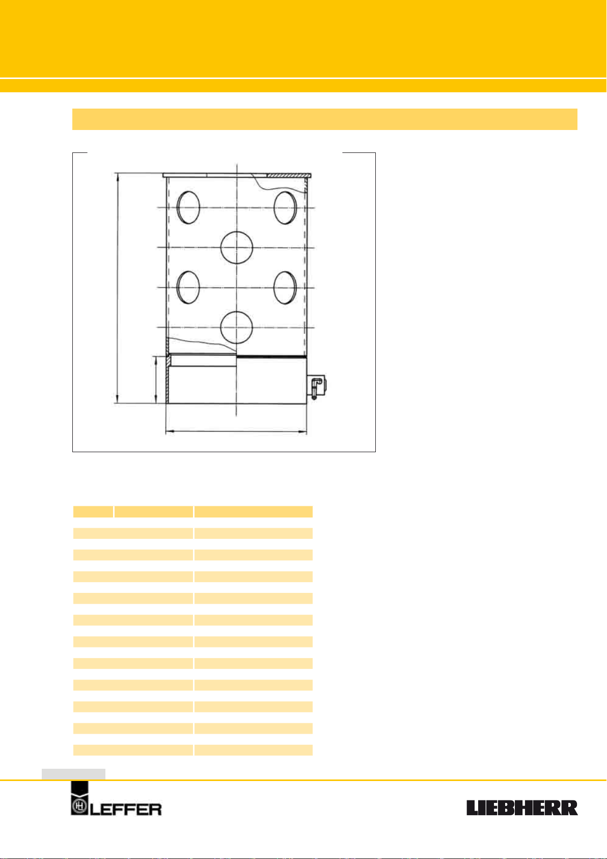
Adapter
Technical Data
L
(upon
request)
290
∅ D
D Nominal diameter Quantity of locking bolts
546 540/478 2
626 620/558 2
606 600/520 2
626 620/540 2
646 640/560 2
666 660/580 2
706 700/620 2
716 710/630 2
726 720/640 2
756 750/670 4
806 800/720 4
886 880/800 4
906 900/820 4
1006 1000/920 4
1086 1080/1000 4
1186 1180/1100 4
1206 1200/1120 4
1256 1250/1170 4
1306 1300/1220 4
1506 1500/1420 6
1806 1800/1720 5
2006 2000/1910 5
Reinforced
female part
with quick
locking bolts
8
Page 9
Bottom Casing
General Remarks
Cutting shoes can be supplied with
half-casing connection or as weld-on
type.
Technical Data
∅ D1
D2
L
∅ d
S1
S2
B
D1/D2 S1 S2 d B Z L - Working length (kg)
mm Quantity of longitudinal bars 4 m 5 m 6 m
540/478
620/558
600/520
620/540
640/560
660/580
700/620
710/630
720/640
750/670
800/720
880/800
900/820
1000/920
1080/1000
1180/1100
1200/1120
1250/1170
1300/1220
1500/1420
1800/1720
2000/1910
10 8 10 31 16 1030 1270 1510
10 8 10 31 18 1200 1460 1740
15 10 13 40 18 1560 1920 2290
15 10 13 40 18 1610 1990 2370
15 10 13 40 18 1660 2050 2440
15 10 13 40 18 1710 2120 2520
15 10 13 40 20 1830 2250 2680
15 10 13 40 21 1840 2280 2710
15 10 13 40 21 1880 2330 2780
15 10 13 40 22 1980 2440 2900
15 10 13 40 24 2120 2610 3110
15 10 13 40 26 2330 2870 3420
15 10 13 40 26 2390 2950 3500
18 10 10 40 30 2870 3560 4240
18 10 10 40 32 3090 3830 4570
18 10 10 40 36 3400 4210 5020
18 10 10 40 36 3470 4310 5330
18 10 10 40 38 3630 4490 5450
18 10 10 40 40 3770 4660 5560
18 10 10 40 45 4380 5420 6460
18 10 10 40 55 5310 6600 7900
18 12 13 45 62 6070 7560 9060
s1
s2
9
Page 10
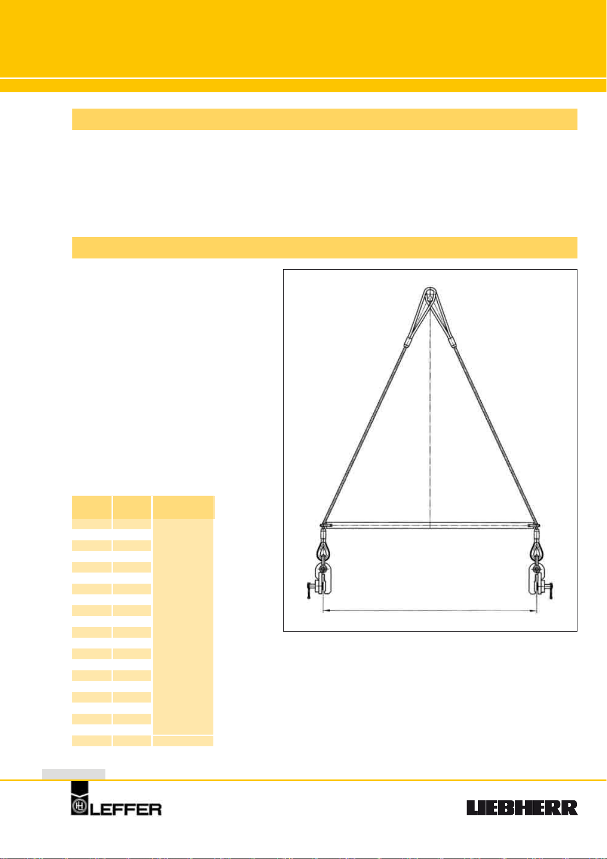
Lifting
Device
General Remarks
The lifting device enables a quick
assembly and dismantling of the
casings without damaging the
conical rings.
Technical Data
D Weight Capacity
mm kg KN
540 90
600 100
620 100
640 100
660 100
700 100
710 100
720 100
750 100
800 102
880 102
900 102
1000 142
1080 142
1180 145
1200 145
1250 145
1300 145
1500 147
1800 150
2000 172
10
100
Quick release
200
Page 11

Casing Funnel
General Remarks
The casing funnel serves as protection for the casing joint and facilitates
the insertion of the drilling tools.
Technical Data
∅ A
H
D1 H A Weight
mm kg
540
620 830 190
600 810 185
620 830 190
640 850 200
660 870 210
700 910 230
710 920 240
720 930 250
750 960 260
800 1010 270
880 1090 280
900 1110 290
1000 1210 310
1080 1290 330
1180 1390 350
1200 1410 365
1250 1460 390
1300 1510 410
1500 1710 450
1800 2010 540
2000 2210 600
500
750 170
∅ D1
11
Page 12

Casings
General Remarks
HD
For a diameter of up to 1500 mm we recommend double-walled casings. For
weight reasons single walled casings
can be used for larger diameters. The
bottom casings would always be double-walled.
Technical Data
D1
B
S
L
D2
D1/D2 S B L - Working length (kg)
mm 1 m 2 m 3 m 4 m 5 m 6 m 8 m
600/520
640/560
700/620
750/670
800/720
880/800
900/820
1000/920
1080/1000
1180/1100
1200/1120
1300/1220
1500/1400
1800/1700
2000/1880
2200/2080
2500/2380
2500/2380
2800/2680
2800/2680
2800/2640
2800/2640
2980/2840
2980/2840
3000/2840
3000/2840
3200/3040
12
20 40 380 672 993 1255 1546 1838 2421
20 40 409 720 1032 1345 1657 1969 2593
20 40 447 789 1131 1473 1815 2157 2841
20 40 481 848 1215 1582 1949 2316 3050
20 40 514 906 1298 1690 2082 2474 3258
20 40 566 998 1430 1862 2294 2726 3590
20 40 580 1022 1464 1906 2348 2790 3674
20 40 640 1133 1626 2119 2612 3105 4091
20 40 690 1190 1720 2260 2820 3350 4420
20 40 760 1350 1925 2510 3100 3680 4840
25 40 860 1600 2340 3080 3820 4560 6030
25 40 945 1745 2545 3375 4150 4950 6550
25 50 1440 2370 3300 4230 5160 6090 7950
25 50 1720 2830 3950 5070 6190 7310 9550
25 60 2190 3430 4670 5910 7150 8390 10870
25 60 2410 3780 5140 6510 7880 9250 11990
25 60 2680 4230 5790 7350 8910 10470 13590
30 60 2810 4670 6530 8400 10270 12140 15880
30 60 3150 5240 7330 9420 11510 13600 17780
32 60 3210 5440 7660 9890 12120 14350 18810
32 80 3890 6120 8340 10570 12800 15030 19490
34 80 3950 6310 8670 11040 13410 15780 20520
32 80 4230 6600 8970 11340 13710 16080 20820
34 80 4290 6810 9330 11850 14370 16890 21930
32 80 4260 6640 9030 11420 13810 16200 20980
34 80 4320 6850 9390 11930 14470 17010 22090
34 80 4610 7315 10020 12725 15430 18140 23550
Page 13

Casings
and Accessories
General Remarks
Heavy Duty Design (Patents in
many countries)
Because of the further development of hydraulic casing oscillators (type VRM) and the new development of hydraulic full 360
degree turning casing rotators
(type RDM) we are now in a position to sink bored piles into
depths of 100 m. In order to meet
the greater demands facing casing columns operating at such
depths, »heavy duty type« casings have been developed.
HD
D1
B
L
s2
s1
∅ d
Technical Data
D2
D1/D2 S1 S2 d B Z L - Working length (kg)
600/520
640/560
700/620
750/670
800/720
880/800
900/820
1000/920
1080/1000
1180/1100
1200/1120
1300/1220
1500/1400
1800/1700
2000/1880
2200/2080
2500/2380
2800/2680
2800/2640
2980/2840
3000/2840
3200/3040
mm
15 10 13 40 18 433 805 1177 1549 1921 2293 3037
15 10 13 40 18 465 862 1259 1656 2053 2450 3244
15 10 13 40 20 509 945 1381 1817 2253 2689 3561
15 10 13 40 22 549 1019 1489 1959 2429 2899 3839
15 10 13 40 24 587 1090 1593 2096 2599 3102 4108
15 10 13 40 26 637 1179 1720 2260 2801 3342 4424
15 10 13 40 26 653 1206 1759 2312 2865 3418 4524
15 10 13 40 30 724 1343 1962 2581 3200 3819 5057
15 10 13 40 32 790 1440 2155 2845 3530 4210 5570
15 10 13 40 36 860 1590 2340 3070 3810 4540 6020
15 10 13 40 36 870 1620 2365 3120 3870 4610 6110
15 10 13 40 40 950 1770 2480 3400 4210 5020 6650
15 10 22 50 45 1485 2520 3555 4590 5625 6660 8735
20 15 13 50 55 1910 3505 5085 6675 8270 9865 13055
20 20 18 60 60 2530 4600 6670 8730 10800 12870 17010
20 20 18 60 66 2785 5065 7350 9635 11920 14205 18775
20 20 18 60 76 3105 5710 8315 10920 13525 16130 21340
25 25 8 60 86 3730 7210 10685 14165 17645 21125 28085
25 25 27 80 86 4530 8335 12135 15945 19755 23565 31185
25 25 27 80 90 4910 8960 13010 17060 21110 25160 33260
25 25 27 80 90 4940 9015 13090 17170 21250 25330 33490
25 25 27 80 98 5280 9640 14000 18440 22800 27160 35960
Quantity of longitudinal bars
1 m 2 m 3 m 4 m 5 m 6 m 8 m
115
13
Page 14

Bottom Casing
General Remarks
Cutting shoes
can be supplied with half-casing
connection or as a weld-on shoe.
Technical Data
HD
114
L
∅ d
s1
s2
S2
S1
200
B
D1/D2 S1 S2 d B Z L - Working length (kg)
600/520
640/560
700/620
750/670
800/720
880/800
900/820
1000/920
1080/1000
1180/1100
1200/1120
1300/1220
1500/1400
1800/1700
2000/1880
2200/2080
2500/2380
2800/2680
2800/2640
2980/2840
3000/2840
3200/3040
mm
15 12 10 40 18 1660 2060 2450 3230
15 12 10 40 18 1780 2200 2620 3450
15 12 10 40 20 1960 2420 2880 3800
15 12 10 40 22 2110 2600 3100 4090
15 15 8 40 24 2430 3010 3600 4760
15 15 8 40 26 2680 3330 3970 5260
15 15 8 40 26 2750 3410 4070 5380
15 15 8 40 30 3060 3800 4540 6010
15 15 8 40 32 3320 4110 4910 6510
15 15 8 40 36 3640 4510 5390 7130
15 15 8 40 36 3700 4590 5480 7260
15 15 8 40 40 4020 4990 5960 7890
15 15 18 50 45 5140 6325 7510 9880
20 20 8 50 55 7380 9156 10950 14520
20 20 18 60 60 8820 10900 12990 17110
20 20 18 60 66 9730 12010 14300 18860
20 20 18 60 76 11070 13670 16280 21490
20 25 8 60 86 14260 17740 21220 28170
20 25 27 80 86 16170 19970 23770 31380
20 25 27 80 90 17260 21310 25350 33450
20 25 27 80 90 17370 21440 25510 33660
20 25 27 80 98 21290 25650 30010 38810
Quantity of longitudinal bars
4 m 5 m 6 m 8 m
D2
∅ D1
14
Page 15

Casing Joint
Technical Data
∅ D1
B
s1 s2
2
3
∅ D2
Fitting for double walled casings
HD
H1
5
7
Z
3
H2
1. Female Part
2. Male Part
6
4
8
3. Locating Key
4. Conical Ring
5. Threaded Ring
6. Schraube Bolt
7. Sealing
1
S
B
Fitting for single walled casings
D1/D2 H1 H2 S S1 S2 B Conical ring Threaded ring Conical bolt Locating key Sealing Weight
mm Quantity Type Quantity Type Quantity Type Quantity Z (mm) kg kg
600/520
640/560
700/620
750/670
800/720
880/800
900/820
1000/920
1080/1000
1180/1100
1200/1120
1300/1220
1500/1400
1800/1700
2000/1880
2200/2080
2500/2380
2800/2680
2800/2640
2980/2820
3000/2840
3200/3040
340 380 22 17 12 40 8 K 75 8 G 75 8 B 32 8 40 10 x 510 188
340 380 22 17 12 40 8 K 75 8 G 75 8 B 32 8 40 10 x550 203
340 380 22 17 12 40 8 K 75 8 G 75 8 B 32 8 40 10 x 610 221
340 380 22 17 12 40 8 K 75 8 G 75 8 B 32 8 40 10 x655 239
340 380 22 17 12 40 8 K 75 8 G 75 8 B 32 8 40 10 x 700 255
340 380 22 17 12 40 8 K 75 8 G 75 8 B 32 8 40 10 x785 281
340 380 22 17 12 40 8 K 75 8 G 75 8 B 32 8 40 10 x 785 288
340 380 22 17 12 40 10 K 115 10 G 115 10 B 32 5 40 10 x900 315
340 380 22 17 12 40 12 K 115 12 G 115 12 B 32 4 40 12 x 975 333
340 380 27 17 12 40 12 K 115 12 G 115 12 B 32 4 40 10 x1075 374
340 380 27 17 12 40 12 K 115 12 G 115 12 B 32 4 40 10 x 1075 375
340 380 27 17 12 40 12 K 115 12 G 115 12 B 32 4 40 10 x1200 413
585 625 27 17 17 50 16 K 165 16 G 165 16 B 42 4 50 10 x 1370 1049
585 625 27 22 17 50 20 k 165 20 G 165 20 B 42 4 50 10 x1670 1241
585 625 27 22 22 60 20 K 220 20 G 220 20 B 48 4 50 12 x 1860 1659
585 625 27 22 22 60 20 K 220 20 G 220 20 B 48 4 50 12 x2050 1830
585 625 27 22 22 60 20 K 220 20 G 220 20 B 48 4 50 12 x 2300 2018
585 625 35 28 28 60 24 K 220 24 G 220 24 B 48 6 50 12 x2600 2268
585 625 35 28 28 80 24 K 300 24 G 300 24 B 65 6 50 12 x 2600 2950
585 625 35 28 28 80 24 K 300 24 G 300 24 B 65 6 50 12 x2800 3230
585 625 35 28 28 80 24 K 300 24 G 300 24 B 65 6 50 12 x 2800 3250
585 625 35 28 28 80 24 K 300 24 G 300 24 B 65 6 50 12 x3000 3470
8. O-Ring
15
Page 16

Lifting
Device
General Remarks
The lifting device enables a quick assembly and dismantling of the casings without damaging the threaded
rings.
Technical Data
HD
D Weight Capacity
mm kg t
600 75
640 75
700 76
750 80
800 85
880 90
900 95
1000 120
1080 120
1180 120
1200 121
1300 150
1500 167
1800 170
2000 171
2200 175
2500 180
2800 260
2980 260
3000 260
3200 260
16
10
Lifting point
20
30
40
Page 17

Casing Funnel
General Remarks
The casing funnel serves as protection for the casing joint and facilitates
the insertion of the drilling tools.
Technical Data
HD
∅ A
∅ D1
H
Nominal diameter D1 H A Weight
mm kg
600 550 460 775 150
640 590 460 815 160
700 650 460 875 175
750 700 460 925 185
800 750 460 975 200
880 830 460 1055 220
900 850 460 1075 225
1000 950 460 1175 250
1080 1030 460 1255 260
1180 1130 460 1355 285
1200 1150 460 1375 295
1300 1250 460 1475 315
1500 1440 530 1655 500
1800 1740 530 1955 600
2000 1930 545 2150 870
2200 2130 545 2350 950
2500 2430 545 2650 1090
2800 2730 545 2950 1230
2800 2710 565 2910 1640
2980 2890 565 3090 1680
3000 2910 565 3110 1700
3200 3110 565 3310 1800
17
Page 18

Single/Double
� 770 � 770
� 970
930
� 850
� 890
L
L
� 1050
� 1070
930
� 1290
1200
� 1360
1200
� 1170
� 1460
Rope Pulley Grab
L 770 - 1460 SK/SZ
Single Rope
Pulley Grab
Chandelier
Lower part
Grab
body
Lower
part
Double Rope
Pulley Grab
Body
Extension
Technical Data
Type Casing diameter Length Jaw capacity Weight
L770 SK
L770 SZ 3325 2410
L850 SK
L850 SZ 3355 2430
L890 SK
L890 SZ 3365 2480
L970 SK
L970 SZ 3535 3150
L1050 SK
L1050 SZ 3565 3180
L1070 SK
L1070 SZ 3585 3240
L1170 SK
L1170 SZ 3630 3335
L1290 SK
L1290 SZ 3805 4550
L1360 SK
L1360 SZ 3860 4445
L1460 SK
L1460 SZ 3895 4570
18
mm mm l kg
880/800 · 900/820
980/900
1000/920
1080/1000 · 1100/1020
1180/1100 · 1200/1120
1180/1100 · 1200/1120
1300/1220
1400/1320
1500/1420 · 1500/1400
1600/1520 · 1600/1500
3725
3755
3765
3935
3965
3985
4030
4205
4260
4295
140
180
210
260
340
440
520
710
830
1060
2740
2760
2810
3480
3510
3570
3665
4880
4775
4900
Page 19

Special Hammer
Grab for Bored Piles
General Remarks
Robust free-fall grab with high closing force especially suitable for boring in detritus soils and for water-logged pile foundations. The pulleys are
equipped with oil-filled maintenance-free life-time
bearings.
Technical Data
Casing Types
600-1000 L 490-890 S
900-1600 L 770-1460 S
1500-2500 L 1350-2250 S
2500-3000 L 2170-2570 S
600 - 3000 mm
Special Hammer Grab
19
Page 20

Single/Double
Rope Pulley Grab
L 1350 - 2100 RK/RZ
Single Rope
Pulley Grab
with teeth
Chandelier
L
1650
Grabbody
Double Rope
Pulley Grab
with teeth
L
1650
Jaw rods
1860 mm
Jaw rods
1700 mm
1800 2100
Technical Data
Type Casing diameter Length Jaw capacity Weight
L1350 RK
L1350 RZ 5080 7750
L1650 RK
L1650 RZ 5220 8000
L1800 RK
L1800 RZ 5240 8310
L2100 RK
L2100 RZ 5420 8840
20
mm mm l kg
1500/1420 · 1500/1400
1800/1720 · 1800/1700
200/1910 · 2000/1880
2500/2400 · 2500/2380
5620
5760
5780
5960
800
900
110
1300
8480
8730
9065
9595
Page 21

� 490
� 490
� 640
� 770
� 850
� 890
� 690
� 530
� 590
L
L
Single/Double
Rope Pulley Grab
L 490 - 890 SK/SZ
Single Rope
Pulley Grab
Chandelier
Lower part
Grab
body
Lower
part
Double Rope
Pulley Grab
Body
Extension
Technical Data
Type Casing diameter Length Jaw capacity Weight
mm mm l kg
L490 SK
L490 SZ 2800 1140
L530 SK
L530 SZ 2820 1145
L590 SK
L590 SZ 2855 1175
L640 SK
L640 SZ 2690 1280
L690 SK
L690 SZ 2710 1305
L770 SK
L770 SZ 2870 1945
L850 SK
L850 SZ 2900 1960
L890 SK
L890 SZ 2910 2010
600/520 · 620/540
620/558 · 640/560 ·
660/580
700/620 · 720/640
750/670
800/720
880/800 · 900/820
980/900
1000/920
3080
3100
3135
2970
2990
3150
3180
3190
45
58
70
70
90
140
180
210
1300
1305
1335
1440
1470
2105
2125
2175
21
Page 22

Single/Double
Rope Pulley Grab
L 2350 - 2750 RK/RZ
Single Rope
Pulley Grab
with teeth
Chandelier
Double Rope
Pulley Grab
with teeth
Grab
body
with
jaw rods
L
2350
L
2750 2350
Technical Data
Type Casing diameter Length Jaw capacity Weight
L2350 RK
L2350 RZ 6435 17375
L2750 RK
L2750 RZ 6605 18540
22
mm mm l kg
2500/2400 · 2500/2380
3000/2840
6970
7140
2500
4500
17700
18865
Page 23

Single/Double
Rope Pulley Grab
L 1350 - 2250 SK/SZ
Single Rope
Pulley Grab
Chandelier
Double Rope
Pulley Grab
Grabbody
LL
1350 1350 1800 2100
Jaw rods
1860 mm
Jaw rods
1700 mm
2250 1650 1650
Technical Data
Type Casing diameter Length Jaw capacity Weight
mm mm l kg
L1350 SK
L1350 SZ 4940 7350
L1650 SK
L1650 SZ 5090 8205
L1800 SK
L1800 SZ 5150 8830
L2100 SK
L2100 SZ 5270 9520
L2250 SK
L2250 SZ 5340 10085
1500/1420 · 1500/1400
1800/1720 · 1800/1700
2000/1910 · 2000/1880
2500/2400 · 2500/2380
2500/2400 · 2500/2380
5480
5630
5690
5810
5880
800
1100
1200
1500
1800
8425
8930
9555
10425
10425
23
Page 24

Hydraulic
Spherical Grab
HLKG/HLKG“CD”
General Remarks
The Hydraulic Spherical Grab type HLKG is used on
jobs, where drilling has to be carried out free of vibrations and/or where partially cased or uncased
drilled shafts are to be produced.
The high deadweight in conjunction with the high
closing force ensures a high efficiency. The hydraulic turning device enables the grab to be turned
100° to ensure a calibration of the borehole.
To recognize and correct any deviation of the vertical excavation direction, all hydraulic spherical
grabs are equipped with a two-axis inclination sensor. The inclination sensor values are monitored inside the operator’s cabin. For uncased drilled shafts
the grab type HLKG “CD” is used. The jaw dimensions are adapted to the respective shaft diameter.
Technical Data
L1L2L
B1 S
Pile diameter Type L L1 L2 B B1 B2 S Weight Capacity
mm kg l
1200
cased
1200
uncased
1300
cased
1300
uncased
1500
cased
1500
uncased
1800
cased
1800
uncased
2000
cased
2000
uncased
HLKG1-118
HLKG1-1200
“CD”
HLKG1-130
HLKG1-1300
“CD”
HLKG1-150
HLKG1-1500
“CD”
HLKG1-180
HLKG1-1800
“CD”
HLKG1-200
HLKG1-2000
“CD”
5760
5760
5760
5760
5760
6640 6715
6690 6800 1160 1170 1200 10550 230
6690 6800
6740 6900 1260 1270 1300 10850 400
6800
6850 7135 1460 1470 1500 12115 680
6975 6975
7030 7345 1720 1750 1800 13850 1030
7030 7470
7115 7625 1900 1950 2000 14290 1500
7045
870
990
990
990
990
1020 960 1080 8650 165
1010 1060 1180 8850 23
1350 1260 1380 9420 420
1650 1560 1670 11050 810
1800 1700 1800 11290 1030
24
Page 25

Single/Double
Rope Pulley Grab
L 2170 - 2570 SK/SZ
Single Rope
Pulley Grab
2350
Double Rope
Pulley Grab
Chandelier
Grab body with
jaw rods
LL
2750 2170 2370 2570
Technical Data
Type Casing diameter Length Jaw capacity Weight
mm mm l kg
L2170 SK
L2170 SZ 6040 17055
L2370 SK
L2370 SZ 6125 17755
L2570 SK
L2570 SZ 6210 18505
2500/2400 · 2500/2380
2800/2680
2800/2680 · 3000/2840
6575
6655
6745
2500
3500
4500
17380
18080
18830
25
Page 26

Mechanical
Spherical Grab
Technical Data
B B2
LKG 0
Guide
Body
L
Lower part
Set of jaws
B1
S
L1
L2
Casing Type L L1 L2 B B1 B2 S Weight Capacity
mm kg l
880/800
900/820
1000/920 LKG 0-100 3700 4380 4700 600 900 870 890 6000 200
1180/1100/
1200/1120
26
LKG 0-88 3700 4295 4545 600 670 740 785 5800 175
LKG 0-118 3700 4460 4815 600 1000 1040 1065 6750 230
Page 27

Mechanical
Spherical Grab
General Remarks
for bored piles 880 – 3200 mm diameter
Double rope grab with high closing force especially
suitable for vibration-free boring in semi-hard and
hard soil conditions.
880-3200 mm
27
Page 28

Mechanical
Spherical Grab
Technical Data
LKG 3
B2
B
Guide
Body
L
L1
L2
Lower part
Set of jaws
B1
Casing Type L L1 L2 B B1 B2 S Weight Capacity
mm kg l
2000/1880 LKG 3-200 4600 5700 6100 1500 1770 1650 1810 15050 970
2200/2080 LKG 3-220 4600 5800 6280 1500 1980 1900 2010 18200 1450
2500/2380 LKG 3-250 4600 6000 6615 1500 2290 2200 2310 19750 2250
2800/2640
2800/2680
2980/2820
3000/2840
3200/3040 LKG 3-320 4600 6325 7230 1500 2980 2900 2980 22100 4650
LKG 3-280 4600 6125 6850 1500 2560 2460 2580 20800 3050
LKG 3-300 4600 6215 7000 1500 2760 2660 2710 21500 3900
S
28
Page 29

Mechanical
Spherical Grab
Technical Data
LKG 1
B
L
B2
Guide
Body
L1
L2
Lower part
Set of jaws
B1
Casing Type L L1 L2 B B1 B2 S Weight Capacity
mm kg l
1180/1100/
1200/1120
1300/1220 LKG 1-130 4700 5630 5745 870 1130 1060 1180 9700 230
1500/1400/
1500/1420
1800/1700
1800/1720
2000/1880
2000/1910
LKG 1-118 4700 5580 5655 870 1020 960 1080 8300 165
LKG 1-150 4700 5745 5955 870 1350 1260 1380 11250 420
LKG 1-180 4700 5915 6285 870 1650 1560 1670 12000 810
LKG 1-200 4700 5980 6460 870 1800 1700 1800 12900 1030
S
29
Page 30

Interlocking
A
D
B
J
K
H
D
d
D
E
Rope
Joint-O
Joint-O
Tremie Pipes
General Remarks
Water-tight interlocking tremie
pipes
The tremie pipes can be supplied in all
diameters and all lengths, also with charging
funnel.
Technical Data
Charging
funnel
NW 150 - NW 250
Tremie pipes 250 mm , 2.5 m long, prior to shipment
Tremie pipe
Collar
Lifting cap
Tube connection
Nominal diameter NW 150 NW 200 NW 250
Tubes for concrete work
D/d mm 194/159 241/203 300/267
Length 1 m kg 26 35 45
Length 2 m kg 42 55 70
Length 3 m kg 57 74 96
Length 4 m
Length 5 m kg 87 113 147
Length 6 m kg 102 132 173
Charging funnel
B mm 400 750 1000
Height A mm 1000 1100 1300
Weight kg 45 85 160
Lifting cap
Height E mm 125 125 125
Weight kg 9 11 12
Tremie pipe
K mm 164 208 272
Width H mm 400 400 450
Length J mm 1200 1200 1500
Weight kg 65 65 75
kg
72 93 121
30
Page 31

30°
500
50
150 150
Chisel
General Remarks
To drive casings through rock
For the different rock conditions we offer two types
of chisel:
Type A - Type B
Type A: Cross chisel with additional tangential cut
ting edges for rock with a compression
strength of less than 1500 kg/cm2.
Type B: Round chisel with a cross inside for rock
with a compression strength of more than
1500 kg/cm2. The teeth are made of high
manganeze steel.
Technical Data
-
Chisel Type B for hard rock
Diameter of casings Width of chisel Length of chisel Weight
mm mm mm kg
640 530 3500 1930
700 590 3500 2200
Cross chisel type A
Round chisel type B
750 640 3500 2400
800 690 3150 2550
880 770 3150
900 770 3150 2700
1000 890 3000 3300
1080 970 3000 3600
1100 970 3000 3700
1180 1070 3500 5000
1200 1070 3500 5000
1300 1190 3500 5200
1500 1370 3500 7000
1800 1640 3500 8000
2000 1840 3850 10000
2200 2040 4000 12000
2500 2220 4000 14000
2800 2520 4000 16000
3000 2700 4000 18000
2700
31
Page 32

Due to improvement and engineering progress we reserve the right to change specifications without notice.
Copyright © · #71006 · 1st Ed · 04/07 · kom DESIGN·1 GmbH München
Stahl- und Apparatebau Hans Leffer GmbH & Co. KG
P.O. Box
20 03 60, D-66044 Saarbrücken/Germany
Tel.: +49 (0) 68 97-7 93-0
Fax: +49 (0) 68 97-7 93-330
info@leffer.de
www.leffer.de
Liebherr-Werk Nenzing GmbH
P.O. Box 10, A-6710 Nenzing/Austria
Tel.: +43 50809 41-0
Fax: +43 50809 41-499
crawler.crane@liebherr.com
www.liebherr.com
 Loading...