

Page 1
Side by Side
Installation
CS 2061 + CS 2060
CS 2081 + CS 2080
HC 2061 + HC 2060
HC 2081 + HC 2080
HCB 2061 + HCB 2060
HCB 2081 + HCB 2080
7082 023-00
Page 2

Parts list of SBS Installation Kit
Image Article number Name of the item
6943 651-00 Heating blanket
9041 321-00 Guide plate
7745 045-00 Angle bracket
9190 201-00 Top cover
2
Page 3
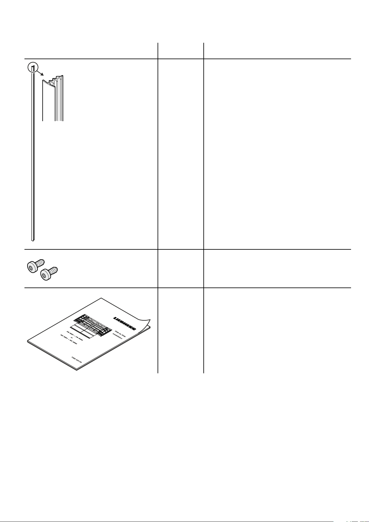
Image Article number Name of the item
7641 503-00 Sealing strip
4084 005-01 Metric screws M 6 x 13
7082 023-00 Installation manual
Other parts used in this installation manual are supplied with the appliance, not with the SBS Kit.
3
Page 4
Side by Side (SBS) Installation
WARNING!
Risk of fire or damage.
The accessory is intended for use only
with a refrigerator that is marked to
indicate such use.
This kit may only be installed with models
CS 2061, CS 2081, HC 2061, HC 2081
HCB 2061, HCB 2081
CAUTION!
The Side by Side installation should only be done by
a trained expert. We recommend this procedure be
done by two people.
note
This installation instruction is applicable for CS
(freestanding) and HC (fully integrated) appliances.
Drawings assume placement of appliances in
cabinetry. There are no seperate drawings for free-
standing applications.
WARNING!
Electrocution hazard.
The refrigerator must be disconnected
from the source of electrical supply
before attempting the installation.
important
The water supply lines for both appliances must be
located already in their correct positions as shown
in chapter „Cabinet opening dimensions“ in the
installation instructions or design guide.
Remove the protective foil from the
1.
outside of both appliances (CS 2060,
CS 2061, CS 2080, CS 2081 only).
Mount the anti tipping brackets for both
2.
appliances.
Refer to chapter
Mounting the anti tipping device
in the installation instructions.
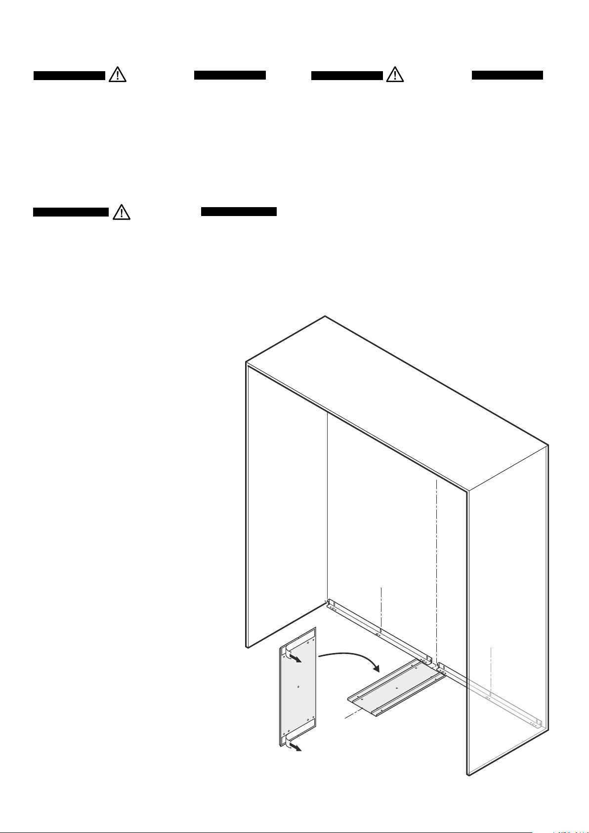
Remove the protective foil of the double-
3.
sided adhesive strips on the bottom of
the guide plate. The guide plate is supplied with the SBS kit.
important
Make sure, that the floor is clean (dust and
grease free), for the adhesive tape.
Adhere the guide plate on the floor. The
4.
rear edge of the plate must have contact
with the anti tipping brackets. Mark a
center line on the floor as illustrated and
align the notches of the guide plate with
this line.
NOTE
The guide plate may also be fastened with
screws through any hole wherever. The
screws are not provided with the appliance
or the kit.
3.
2.
2.
4.
4
Page 5

5.
note
Step 5 is for HC (fully integrated) appli-
ances only.
5. Remove the inner supports.
6.
7.
Loosen the protective foil of the
6.
heating blanekt top. Pull down the
foil for approx. 4".
important
Do not remove the protective foil
completely.
Adhere the heating blanekt on the top of the left unit.
7.
Upper edge of blanekt 4-1/2" from the appliance top.
Front edge of blanekt 1-1/2" from the appliance housing
backwards.
Remove the protective foil a bit at a time as you go and
flatten the heating foil top down.
important
There should be no air pockets between heating foil and
appliance wall.
5
Page 6

Bend the lower tongue of the heating
8.
blanekt around the corner and adhere
to the back of the appliance.
note
Heating blanket only has 17 W, so no
heat can be felt after installation.
Connect the cable of the heating blanekt with the
9.
socket in the compressor compartment.
Make sure, that the heater cable is not laying on the
floor. Please put the cable inside the compressor
8.
important
compartment.
9.
important
After the cable of the heating blanket is connected,
insert the cable into the pre-installed cable holder.
10.
10. Open the doors and remove both covers.
6
Page 7

note
Step 11 is for HC (fully integrated) appli-
ances only.
11. Apply cover strips above, between and
below the securing plates on the left
side wall of the left appliance and on the
right side wall of the right appliance.
Cut the cover strips to the length as
shown in Step 11 using a pair of heavy
duty scissors or a utility knife.
11.
11.
Adhere the cover strips
leaving a gap of 1/4" to
each securing plate to
prevent interference when
installing the covers.
12. Move the left appliance in front of the recess.
Move the power supply line to the area of the
electrical outlet.
Do not connect to the electrical outlet
before the installation is completed
and the water line is connected to the
solenoid valve.
Insert the water supply line for the ice maker
into its intended opening on the appliance
rear.
Refer to chapter
Connection to the water supply
in the installation instructions.
Slide the appliance into the recess or against
the back wall with freestanding applications.
Be sure the appliance castors runs in the
intended rail of the guide plate.
Install the right appliance in the same way.
WARNING!
12.
7
Page 8

13. Align both appliances.
Refer to chapter
installation instructions.
The appliances must be in line at the front and in height
Leveling the appliance in the
important
and must be aligned vertical.
14.
13.
14. Open the doors and remove the
screws. These screws are needed
in the next step.
15. Attach the angle bracket supplied with the SBS Kit
and fasten with the screws of step 14 through the
two center holes.
16. Fasten the bracket at left and right with the M 6 x 13
metric screws supplied with the SBS kit.
14.
15.
16.
8
Page 9

17. Click the cover supplied with
the SBS kit into place.
18. Open the doors and press the seal-
ing strip supplied with the SBS kit
into the gap at the front.
17.
18.
Complete the Side by Side installation considering the following chapters in the
installation instructions.
19. Connection to the water supply (from passage 5 - 9)
20. Fastening the appliance in the recess
21. Before mounting the door panels
22.
Mounting the attachment brackets onto the door panels
23. Mounting the refrigerator door panel
24. Mounting the freezer drawer panels
25. Mounting the ventilation grille
9
Page 10

Notes
10
Page 11

Notes
11
Page 12

For Service in the U.S.
Liebherr Service Center
Toll Free: 1-866-LIEBHER or 1-866-543-2437
Email: Service-appliances.us@liebherr.com
PlusOne Solutions, Inc.
3501 Quadrangle Blvd, Suite 120
Orlando, FL 32817
For Service in Canada
Liebherr Service Center
Toll Free: 1-888-LIEBHER or 1-888-543-2437
www.euro-parts.ca
EURO-PARTS CANADA
39822 Belgrave Road
Belgrave, Ontario, N0G 1E0
Phone: (519) 357-3320
Fax: (519) 357-1326
www.liebherr-appliances.com
 Loading...