

Page 1

Installation instructions
For NoFrost combined refrigerator-freezers Page 6
GB
7082 375-00
CBNes 62 410
Page 2
GB
Setting up
• Avoid positioning the appliance in direct sunlight or near cookers,
radiators and similar sources of heat.
• The oor on which the appliance stands should be horizontal and
level.
• The ventilation grilles should not be obstructed. Always ensure
that there is good ventilation and that the outward owing air is
able to escape.
• Do not place heat-emitting appliances, e.g. microwave oven,
toaster, etc., on top of the appliance.
• Standard EN 378 species that the room in which you install your
appliance must have a volume of 1 m³ per 8 g of R 600a refrigerant
used in the appliance, so as to avoid the formation of inammable
gas/air mixtures in the room where the appliance is located in the
event of a leak in the refrigerant circuit. The quantity of refrigerant
used in your appliance is indicated on the type plate on the inside
of the appliance.
• Do not connect the appliance to the supply with other equipment
using an extension cable - risk of overheating.
Connecting to the mains
Power supply (AC) and voltage at the operating point must comply
with the details on the type plate, which is located on the inside left
of the appliance, next to the vegetable bins. The socket must be
fused with a 10 A fuse or higher, it must be away from the rear of
the appliance and must be easily accessible.
Connect the appliance with a properly earthed fused plug
and socket only.
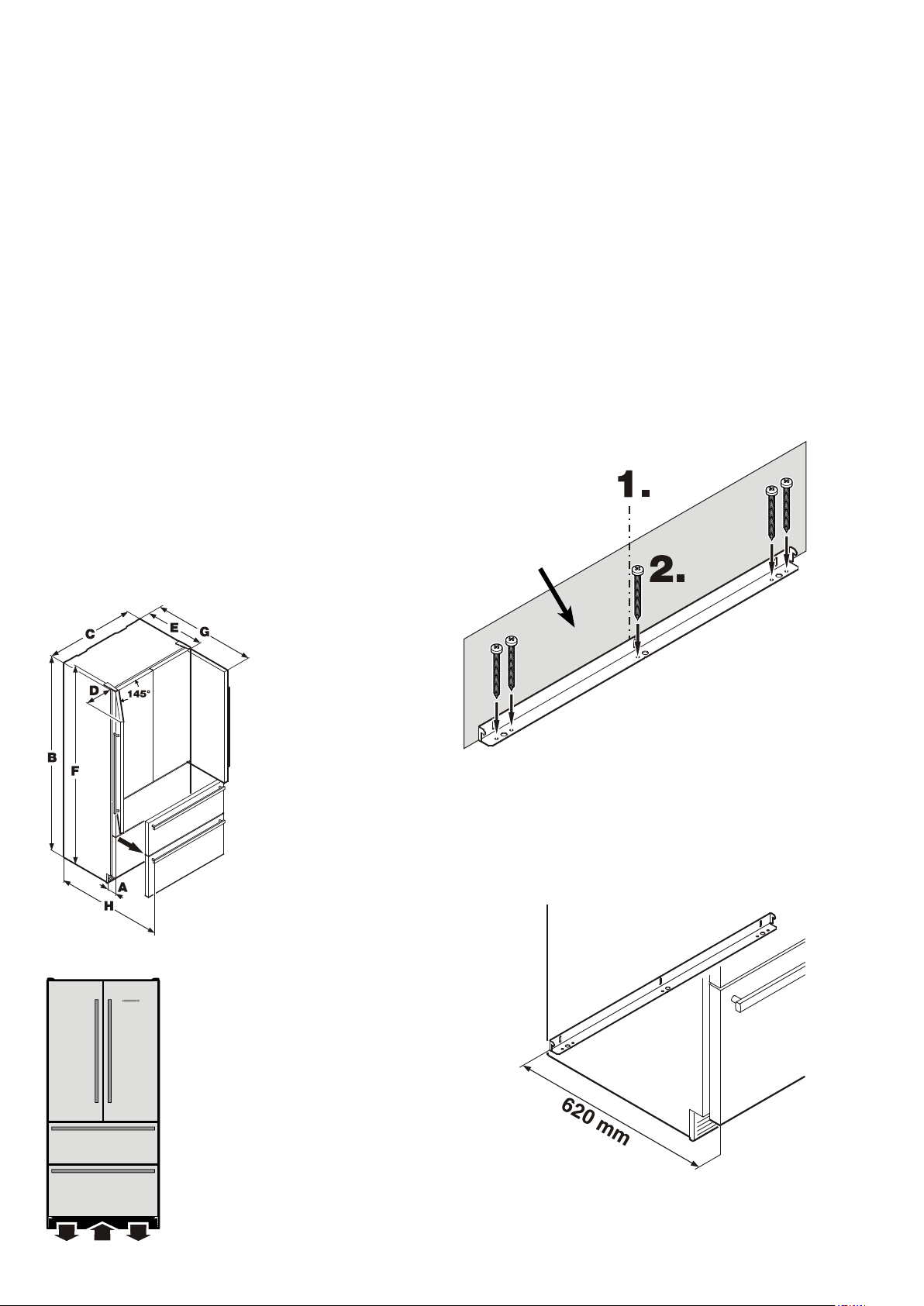
Mounting the anti-tipping device
Caution!
The supplied anti-tipping bracket must be installed in all
cases.
This prevents the appliance from tipping over when the fully loaded
door is opened.
Installation:
1. Mark the centre line of the appliance on the wall.
Align the anti-tipping bracket centre to the centre line on the
wall.
Caution!
Ensure that there are no electric cables or water pipes in
the wall section to which the anti-tipping bracket is to be
secured. These could be damaged during installation.
2. Secure the anti-tipping bracket to the floor using the 5 screws
(6 mm x 60 mm) included in the accessory pack.
Important!
When securing the anti-tipping bracket to a concrete floor,
use suitable plugs!
Appliance dimensions
Appliance venting
A. 90 mm
B. 2027 mm
C. 910 mm
D. 279 mm
E. 615 mm
F. 2039 mm
G. 1037 mm
H. 1002 mm
Wall
If the appliance is installed between furniture that has a depth of
more than 620 mm, the appliance will not be in contact with the
anti-tipping bracket.
In this case, it must be installed in a space of 620 mm from the front
face of the appliance to the rear edge of the anti-tipping bracket.
The required air flow is directed through the
plinth.
It is important to use the provided ventilation
grille for the ventilation opening.
This opening must not be covered.
6
Page 3

GB
Fitting the top anti-tipping bracket
1. Mount the anti-tipping bracket provided on the wall using 6 x
60 screws.
Ice maker
The ice maker is tted in the freezer compartment of the combined
refrigerator-freezer. It must be connected to the mains water supply to work.
Safety instructions and warnings
• Do not connect to the water supply while the combined refrigerator-freezer is connected to the electricity supply.
• The connection to the mains water supply may only be made
by trained personnel.
• The water quality must comply with the drinking water directives of the country in which the appliance is used.
• The ice maker is designed exclusively to make ice cubes in quantities required by a household and may only be operated with water
suitable for this purpose.
• All repairs and work on the ice maker may only be carried out by
customer service personnel or other trained personnel.
• The manufacturer cannot accept liability for damage caused
by a faulty connection to the mains water supply.
Position of the water connection
2. Clip both attachment brackets into the
transport grips of the appliance.
The water shut-o valve must be positioned within the areas marked
in grey.
Side view
7
Page 4

GB
Connection to the water supply
The water pressure must be between 0.15 and 0.6 MPa (1.5 6 bar).
3. Push the appliance to the wall until the compressor mounting
plate touches the anti-tipping bracket.
Important:
If the water lter is inserted in the appliance, the water
pressure must lie between 0.3 and 0.6 MPa (3 - 6 bar). If
the water pressure with the inserted water lter is too low,
this may cause the ice maker to malfunction.
The water supply to the appliance must be through a cold water
pipe that can withstand the operating pressure and complies with
the hygiene regulations. For this, use the stainless steel hose supplied (length 3 m).
1. Insert the bent section of the hose through
the opening at the rear of the appliance.
Caution!
To prevent the appliance from tipping forwards, the compressor
mounting plate must be touching the anti-tipping bracket!
Wall
Appliance
Anti-tipping bracket
Compressor mounting
plate
2. Connect the hose to the solenoid valve
at the front side of the appliance.
Important!
After the IceMaker has been switched on, the water supply system
must be bled. See the section Bleeding the ice maker in the
operating instructions.
4. Connect the hose to the shut-off tap.
Open the shut-off tap and check the system for leakage.
Caution!
Do not connect the appliance to the power supply until the
installation is completed.
8
Page 5

GB
Levelling the appliance
1. Adjust the height of the appliance at the front by twisting the
adjustable feet
Caution!
The front feet of the appliance must be firmly placed on the
floor.
1
(A/F 27).
Mounting the dust filter
The supplied dust filter prevents that dirt enters the motor compartment, reducing the refrigeration performance. Therefore always
install the dust filter.
1. Pull the bottom freezer drawer right out.
2. Remove the protective film from the dust filter. Insert the filter at
the bottom, press the button down and click the filter into place.
Mounting the ventilation grille
Important!
To ensure fault-free operation of the appliance, you must
install the supplied ventilation grille.
2. Turn the adjusting bars
(A/F 5) clockwise until the compressor mounting plate touches
the anti-tipping bracket.
Top anti-tipping bracket
3. Secure the appliance with M5 x 7
screws.
2
Do not obstruct the ventilation opening or cover it with a
panel!
9
 Loading...